

Page 1

TruVision
Vandal Dome Installation
Guide
TVD
TVD
TVD-2405/TVD-4405
P/N 1073166-EN • REV A • ISS 31MAR16
High Definition TVI
-2402/TVD-4402
-2404/TVD-4404
Page 2

2 Installation Guide
Page 3

Content
Product overview 4
Camera description 6
Installation 9
Operating temperature range 14
Program 14
Setup menu 19
Specifications 21
Legal and Regulatory information 23
Installation Guide 3
Page 4
Product overview
This is the Installation Guide for the TruVision High
Definition TVI dome TVD-2402/TVD-4402,TVD2404/TVD-4404 and TVD-2405/TVD-4405. This
guide describes a standard installation.
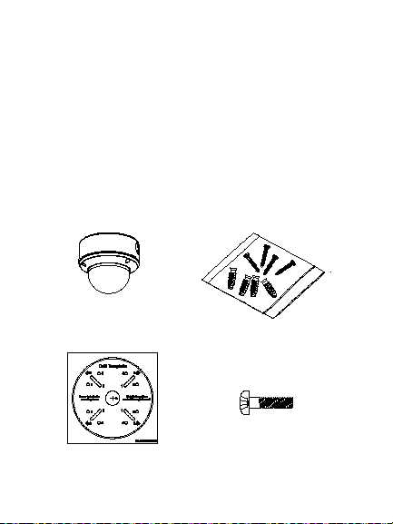
Package contents
Camera with power
and video output
cables
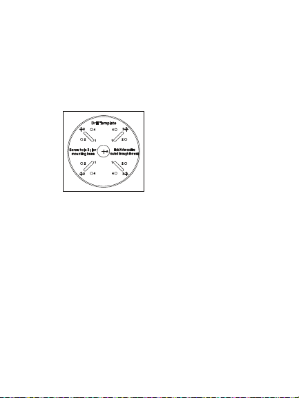
Template
4 Installation Guide
4 screws and 4
anchors for wall or
ceiling installation
3 screws to install
the camera to the
back box
Page 5
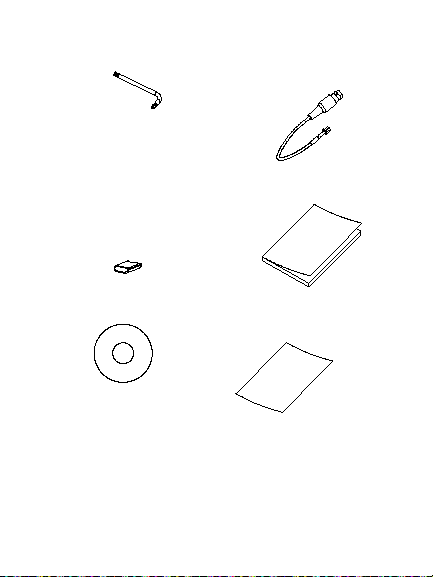
Hex wrench
Monitor output
cable
Spare rubber
knockout
There is a rubber knockout
on the camera back box.
This is for future use.
CD
Installation Guide 5
Installation Guide
• WEEE and Battery
Disposal sheets
Page 6
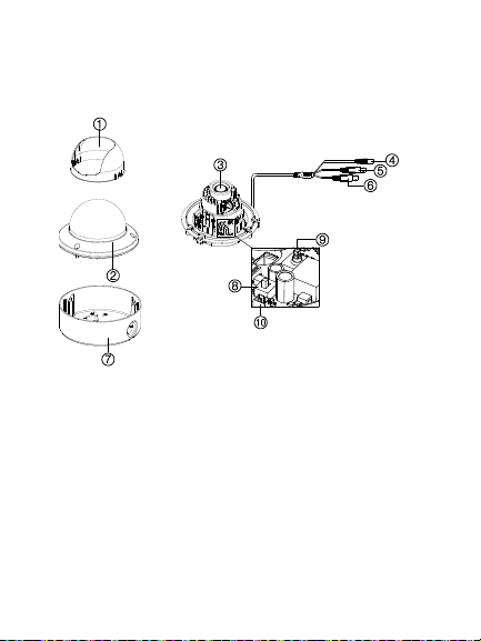
Camera description
10. CVBS output port
TVD-2402/TVD4402:
1. Dome liner
2. Bubble
3. Lens
4. Power cable
5. CVBS video output
cable (black)
6 Installation Guide
6. TVI video output
cable (grey)
7. Back box
8. Switch (Left =
WDR / Right =
CVBS)
9. Menu button
Page 7
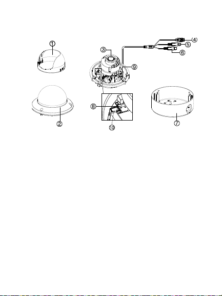
TVD-2404/4404 and TVD2405/4405:
10. CVBS output port
1. Dome liner
2. Bubble
3. Lens
4. Power cable
5. CVBS video output
cable (black)
Installation Guide 7
6. TVI video output
cable (grey)
7. Back box
8. Switch (Left =
WDR / Right =
CVBS)
9. Menu button
Page 8

Note:
Please check the camera output settings
before setting up a system. The TVI video
output can be only connected to DVR with
TVI signal input. The CVBS output supports a
standard CVBS monitor (or test monitor), an
encoder or a DVR.
For 720P Dome cameras TVD-2402/TVD-
4202, the CVBS and TVI output can not be
used at the same time. Use the built-in switch
to select the camera video output.
For 1080P Dome cameras TVD-2404/TVD4404 and TVD-2405/TVD-4405, use the builtin switch to enable/disable the WDR feature.
When the WDR feature is enabled, the CVBS
output will be blocked.
8 Installation Guide
Page 9
Installation
To install the camera on a ceiling:
1. Using the template, place it level against the
mounting surface and mark the position of the
mounting holes.
2. Following all local safety regulations, drill and
prepare the mounting holes.
3. Remove the camera from its back box.
4. Loosen the three screws on the edge of the
bubble with the supplied hex wrench.
5. Remove the bubble and the dome liner.
Installation Guide 9
Page 10

6. Secure the back box to the ceiling with the
supplied screws.
Note: Please remove the rubber knockout for
cable routing outside of the camera, when
required.
10 Installation Guide
Page 11

7. Using a 75-ohm coaxial video cable, connect
the camera TVI video output to a TVI DVR, and
connect a 12 VDC or 24 VAC power supply to
the power cable.
8. Align the camera with the back box and tighten
the screws to fasten the camera to the back
box.
7. Adjust the surveillance angle:
1) View the camera image on a monitor.
Installation Guide 11
Page 12

2) Rotate the camera block to adjust the pan
~
~
~
direction [0 to 355°].
3) Loosen the tilting lock screw.
4) Rotate the camera block to adjust the tilt
direction [0 to 90°].
5) Tighten the tilting lock screw.
6) Rotate the camera lens holder [0 to 355°]
to adjust the lens to the surveillance angle.
8. Zoom and focus adjustment
a) Manually adjust the zoom and focus of TVD-
2402/TVD-4402 and TVD-2404/TVD-4404.
1) View the camera image using the monitor.
12 Installation Guide
Page 13

2) Loosen the zoom lever and move the
Zoom
Focus
screw between T (Tele) and W (Wide) to
obtain the appropriate angle of view.
3) Tighten the zoom lock screw.
4) Loosen the focus lever and move the
screw between F (Far) and N (Near) to
obtain the optimum focus.
5) Tighten the focus lock screw.
b) TVD-2405/TVD-4405 has a motorized lens.
Adjust its zoom and focus by using the zoom
and focus buttons on the PTZ panel of a
connected recorder or TVS-C200 controllor.
Installation Guide 13
Page 14

Operating temperature range
The operating temperature of the TVD-2402/4402
and TVD-2404/4404 cameras is -30 to +60 °C (-22
to +140 °F).
When the camera initially starts up, the heater will
start to work automatically when the temperature is
below -10 °C (14 °F). However, with continuous
operation the heater will not work until the internal
temperature drops below -30°C (-22 °F). It will then
be disabled when the temperature reaches -10 °C
(14 °F). The heater only works under 24 VAC.
Program
Once the camera hardware has been installed, you
can then program the camera.
The camera has a built-in OSD button and supports
UtC (Up-to-Coax) control over both CVBS and TVI
outputs.
14 Installation Guide
Page 15

Using the camera buttons
Please press the Menu button to call up the OSD
menu and select an OSD item.
Press the button up/down to move the cursor up or
down to an OSD item.
Press the button left/right to move cursor left or right
to adjust the value of a selected OSD item.
Using a TVI output
Once the camera hardware has been installed, you
can configure the camera settings on the TVI DVR.
Connect the TVI cable to the DVR, as shown below.
Installation Guide 15
Page 16

Access the PTZ menu of the connected DVR, set
the TruVision-Coax protocol and use the PTZ
control panel to configure the camera.
Click Iris+ to access to the camera OSD menu and
select an OSD item.
Click the directional buttons UP or DOWN to move
the cursor up or down to an OSD item.
Click the directional buttons LEFT or RIGHT to
move cursor left or right to adjust the value of a
selected OSD item.
Note: The TVD-2405/TVD-4405 camera has a
motorized lens. Use the ZOOM and FOCUS buttons
to adjust its zoom and focus.
For more details, refer to the TVI DVR user manual.
Using a CVBS output
A TVS-C200 (purchase separately) can be used to
program the camera over its CVBS output, not the
TVI video output.
Connect a monitor and the TVS-C200 controller (if
required) as shown below.
16 Installation Guide
Page 17

Press the OK button of the TVS-C200 for a few
seconds until you see the OSD menu display on the
monitor. The OK button is also used to select an
OSD item.
Use the directional buttons to move the cursor and
change a value.
For more details, refer to the TVS-C200 user
manual.
TVD-2402/TVD-4402
The camera has CVBS and TVI dual video outputs.
Set the built-in switch to CVBS for viewing the
program on a standard monitor.
Installation Guide 17
Page 18

The TVI signal is blocked until the camera
configuration is complete and the switch is reset to
TVI.
TVD-2404/TVD-4404 and TVD-2405/TVD-4405
The camera has the CVBS and TVI dual video
outputs. The built-in switch is for WDR/CVBS
selection. Set the built-in switch to CVBS to view the
setup menu on a standard monitor.
When the programing is finished, you can change
the switch setting to W DR to enable the WDR
feature. In such case, the CVBS output will be
disabled.
If the switch is set to CVBS, the WDR feature is
disabled and the camera has the both CVBS and
TVI output available.
18 Installation Guide
Page 19

Setup menu
TVD-2402/TVD-4402:
Installation Guide 19
Page 20

TVD-2404/TVD-4404, TVD-2405/TVD-4405:
20 Installation Guide
Page 21

Specifications
Power supply
24 VAC/12 VDC
Current
Power
consumption
TVD-2402/ TVD-4402:
Weight (net)
TVD-2402/ TVD-4402:
Installation Guide 21
12 VDC: 300 mA max.
24 VAC: 210 mA max.
TVD-2404/TVD-4404:
12 VDC: 375 mA max.
24 VAC: 270 mA max.
TVD-2405/TVD-4405:
12 VDC: 1 A max.
24 VAC: 500 mA max.
12 VDC: 3.5W max.
24 VAC: 5 W max.
TVD-2404/TVD-4404:
12 VDC: 4.5 W max.
24 VAC: 6.5 W max.
TVD-2405/TVD-4405:
12 VDC: 12 W max.
24 VAC: 12 W max.
641 g / 1.41 lb. (without back box)
932 g / 205 lb. (with back box)
Page 22

Dimensions
Ø145.3 x 124.2 mm
(Ø 5.72 x 4.89 in. )
22 Installation Guide
Page 23

Legal and Regulatory
information
Class A: This equipment has been tested and found to comply with
erated in a commercial environment. This equipment generates,
and used in accordance with the instruction manual, may cause
Copyright:
© 2016 United Technologies Corporation,
Interlogix is part of UTC Climate, Controls & Security, a unit of
United Technologies Corporation. All rights reserved.
Trademarks and patents:
Trade names used in this document may be trademarks or
registered trademarks of the manufacturers or vendors of the
respective products.
Manufacturer:
Interlogix
2955 Red Hill Avenue, Costa Mesa, CA 92626-5923, USA
Authorized EU manufacturing representative:
UTC Fire & Security B.V.
Kelvinstraat 7, 6003 DH Weert, The Netherlands
Certification:
FCC compliance: Class A
the limits for a Class A digital device, pursuant to part 15 of the
FCC Rules. These limits are designed to provide reasonable
protection against harmful interference when the equipment is
op
uses, and can radiate radio frequency energy and, if not installed
Installation Guide 23
Page 24

harmful interference to radio communications. Operation of this
equipment in a residential area is likely to cause harmful
interference in which case the user will be required to correct the
interference at his own expense.
ACMA compliance
Notice! This is a Class A product. In a domestic environment this
product may cause radio interference in which case the user may
be required to take adequate measures.
Canada
This Class A digital apparatus complies with Canadian ICES-003.
Cet appareil numérique de la classe A est conforme à la norme
NMB-0330 du Canada.
European Union directives:
12004/108/CE (EMC directive): Hereby, UT C Fire & Security declares
that this device is in compliance with the essential requirements and
other relevant provisions of Directiv e 2004/108/EC.
Contact information:
For contact information, see www.interlogix.com or
www.utcfssecurityproducts.eu
2012/19/EU (WEEE directi ve): Products marked
with this symbol cannot be disposed of as
unsorted municipal waste in the European Union.
For proper recycling, return t his product to your
local supplier upon the purchase of equiv alent new
equipment, or dispose of it at designated collection
points. For more inf ormation see:
www.recyclethis.info.
24 Installation Guide
Page 25

Page 26

Page 27

Page 28

 Loading...