

Page 1

TruVision IR
Dome Camera
TVD
Installation
P/N 1072923 • REV A • ISS 10FEB15
-2202/TVD-4202
Guide
Page 2

Page 3

Contents
Product overview 2
Camera description 4
Installation 5
Programming 9
Specifications 10
Setup menu 11
Regulatory information 12
Installation Guide 1
Page 4
Product overview
This is the TruVision IR Dome Camera Installation
Guide for models TVD-2202/TVD-4202. This guide
describes a standard installation.
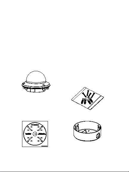
Package contents:
Camera with power
and video output
cables
Template
2 Installation Guide
4 M4 screws (4 x
25 mm) and 4 dry
wall anchors (Ø7.5
x 24.5 mm) for wall
or ceiling
installation
Back box
Page 5
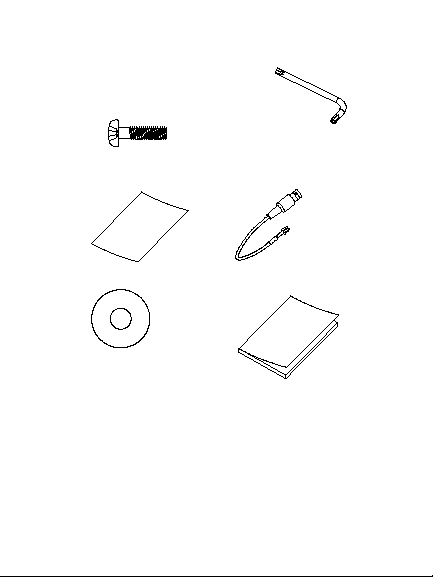
3 M4 screws (3 x
25 mm) screws to
install the camera
to the back box
Hex wrench
• WEEE and Battery
Disposal
CD
Installation Guide 3
Monitor output
cable
Installation Guide
Page 6

Camera description
4. Menu button
1. Dome liner
2. Bubble
3. Auxiliary video
output
4 Installation Guide
5. Power cable
6. Video cable
7. Lens
8. Back box
Page 7

Installation
To install the camera:
1. Using the template, place it level against the
mounting surface and mark the position of the
mounting holes.
2. Following all local codes, drill and prepare the
mounting holes.
3. Remove the camera from its back box.
4. Loosen the three set screws on the edge of the
bubble with the supplied hex wrench. Remove
the bubble and the dome liner.
Installation Guide 5
Page 8

4. Secure the back box to the ceiling with the
supplied screws.
5. Connect a 75-ohm coaxial video cable to the
video cable and a power supply to the power
cable.
6. Align the camera with the back box and tighten
the set screws to secure the camera to the
back box.
6 Installation Guide
Page 9

7. Adjust the surveillance angle:
1) View the camera image on a monitor.
2) Rotate the panning table to adjust the pan
direction [0 to 355°].
3) Loosen the tilting lock screw.
4) Rotate the tilting table to adjust the tilt
direction [0 to 90°].
5) Tighten the tilting lock screw.
6) Rotate the camera lens holder [0 to 355°]
to adjust the lens to the surveillance angle.
Installation Guide 7
Page 10

8. Zoom and focus adjustment.
~
~
~
1) View the camera image using the monitor.
2) Loosen the zoom lever and move the
screw between T (Tele) and W (Wide) to
obtain the appropriate angle of view.
3) Tighten the zoom lock screw.
4) Loosen the focus lever and move the
screw between F (Far) and N (Near) to
obtain the optimum focus.
5) Tighten the focus lock screw.
8 Installation Guide
Page 11

Zoom
Focus
Programming
Once the camera hardware has been installed, the
camera can be configured by using the built-in OSD
button or a TVS-C200 controller (purchase
separately).
The Setup menu provides access to the camera
configuration options. See page 11 for an overview
of the menu. Please refer to the configuration
manual for further information on setting up the
camera.
Program the camera by attaching a standard video
monitor to the system.
Installation Guide 9
Page 12

To access the Setup menu:
1. Press the OSD control button (Enter) to access
the Main menu and its submenus.
2. Push the button up, down, left and right to
move between menu options.
3. Press the OSD control button to select an
option.
4. When in a submenu, select Return to return to
the previous menu.
5. To exit the Main menu, move the cursor to Exit
at the bottom of the screen and press Enter. All
changes are saved.
Specifications
Power supply 24 VAC/12 VDC
Current Max. 580 mA
Power consumption Max. 7W
Weight (net) 1.95 lb. (880 g)
Dimensions
10 Installation Guide
Ø 5.72 x 4.89 in.
(Ø145.3 x 124.2 mm)
Page 13

Setup menu
Installation Guide 11
Page 14

Regulatory information
Copyright:
Class A: This equipment has been tested and found to comply with
erated in a commercial environment. This equipment generates,
equipment in a residential area is likely to cause harmful
© 2015 United Technologies Corporation.
Interlogix is part of UTC Building & Industrial Systems, a unit of
United Technologies Corporation. All rights reserved.
Trademarks and patents:
Trade names used in this document may be trademarks or
registered trademarks of the manufacturers or vendors of the
respective products.
Manufacturer:
Interlogix
2955 Red Hill Avenue, Costa Mesa, CA 92626-5923, USA
Authorized EU manufacturing representative:
UTC Fire & Security B.V.
Kelvinstraat 7, 6003 DH Weert, The Netherlands
Certification:
N4131
FCC compliance: Class A
the limits for a Class A digital device, pursuant to part 15 of the
FCC Rules. These limits are designed to provide reasonable
protection against harmful interference when the equipment is
op
uses, and can radiate radio frequency energy and, if not installed
and used in accordance with the instruction manual, may cause
harmful interference to radio communications. Operation of this
12 Installation Guide
Page 15

interference in which case the user will be required to correct the
interference at his own expense.
ACMA compliance
Notice! This is a Class A product. In a domestic environment this
product may cause radio interference in which case the user may
be required to take adequate measures.
Canada
This Class A digital apparatus complies with Canadian ICES-003.
Cet appareil numérique de la classe A est conforme à la norme
NMB-0330 du Canada.
European Union directives:
12004/108/CE (EMC directive): Hereby, UT C Fire & Security declares
that this device is in compliance with the essential requirements and
other relevant provisions of Directive 2004/108/EC.
2012/19/EU (WEEE directi ve): Products marked
with this symbol cannot be disposed of as
unsorted municipal waste in the E uropean Union.
For proper recycling, return this product t o your
local supplier upon the purc hase of equivalent new
equipment, or dispose of it at designated collection
points. For more information see:
www.recyclethis.info.
Contact information:
For contact information, see www.interlogix.com or
www.utcfssecurityproducts.eu
Installation Guide 13
Page 16

 Loading...