

Page 1

TruVision Bullet IR
g
p
p
g
p
у
p
Camera
EN Pocket Guide
DE Kurzanleitun
ES Guía de bolsillo
FR Guide de
IT Guida ra
NL Beknopte handleidin
PL Kieszonkowy przewodnik
PT Guia Rá
RU Карманное р
TR Ce
P/N 1076544 • REV A • ISS 16APR12
Kılavuzu
oche
ida
ido
ководство
Page 2

Page 3

Contents / Inhalt / Guía de
bolsillo / Table des matières /
Indice / Inhoudsopgave / Spis
treści / Índice / Содержание /
İçindekiler
Figures ........................................................ 3
EN .............................................................. 12
DE .............................................................. 16
ES .............................................................. 20
FR .............................................................. 24
IT ................................................................ 28
NL .............................................................. 32
PL .............................................................. 36
PT .............................................................. 41
RU .............................................................. 45
1
Page 4

TR ............................................................... 50
Legal / Rechtliche Angaben / Información
legal / Informations légales / Note legali /
Juridisch / Informacje prawne /
Informação legal / Нормативно-
правовые аспекты / Yasal ...................... 54
2
Page 5
Figures
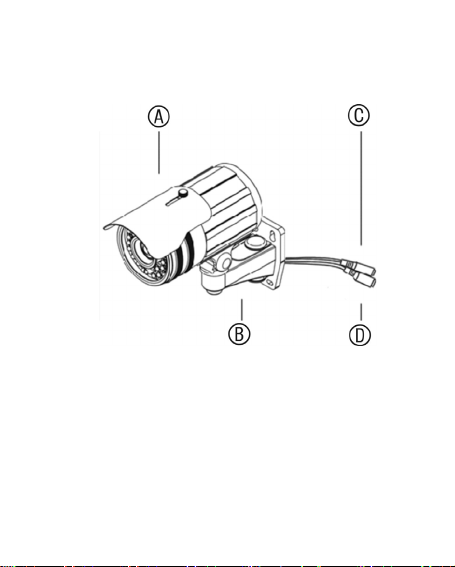
EN Figure 1: Parts of the camera
A. Sunshield; B. Hidden cable
bracket; C. Power cable; D. Video
cable
DE Abbildung 1: Teile der Kamera
A. Sonnenschutz; B. Verborgene
Kabelhalterung; C. Stromkabel;
D. Videokabel
3
Page 6

ES Figura 1: Partes de la cámara
A. Protección solar; B. Soporte del
cable oculto; C. Cable de
alimentación; D. Cable de vídeo
FR Figure 1 : Éléments de la caméra
A. Pare-soleil ; B. Support de câble
masqué ; C. Câble d'alimentation ;
D. Câble vidéo
IT Figura 1: Parti della telecamera
A. Parasole; B. Supporto del cavo
nascosto; C. Cavo di alimentazione;
D. Cavo video
NL Afbeelding 1: Onderdelen van de
camera
A. Zonwering; B. Verzonken
kabelsteun; C. Voedingskabel;
D. Videokabel
PL Rysunek 1: Elementy kamery
A. Osłona przeciwsłoneczna;
B. Uchwyt z kablem wewnątrz;
C. Kabel zasilania; D. Przewód
wideo
4
Page 7

PT Figura 1: Componentes da
ç
câmara
A. Protector de sol; B. Suporte de
cabo oculto; C. Cabo de
alimentação; D. Cabo de vídeo
RU Рис. 1. Детали камеры
A. Защита от солнца;
B. Кронштейн скрытого кабеля;
C. Кабель питания;
D. Видеокабель
TR Şekil 1: Kameranın parçaları
A. Güneşlik; B. Gizli kablo desteği;
kablosu; D. Video kablosu
C. Gü
5
Page 8
r
j
r
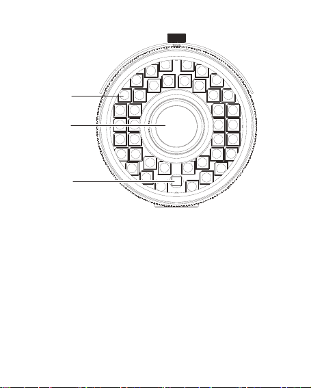
EN Figure 2: Camera front
A. LED IR lights (total number of lights
varies by model); B. Lens; C. Light
senso
DE Abbildung 2: Vorderseite der
Kamera
A. LED-IR-Leuchten (Gesamtzahl der
Leuchten hängt von Modell ab);
B. Ob
ektiv; C. Lichtsenso
6
Page 9

ES Figura 2: Parte delantera de la
p
j
r
y
cámara
A. Luces LED IR (la cantidad total de
luces varía en función del modelo);
B. Lente; C. Sensor de luz
FR Figure 2 : Avant de la caméra
A. Témoins lumineux LED IR
(le nombre total de témoins varie
selon le modèle) ; B. Objectif ;
teur de luminosité
C. Ca
IT Figura 2: parte anteriore della
telecamera
A. IR LED (il numero complessivo di
LED varia a seconda del modello);
B. Obiettivo; C. Sensore luce
NL Afbeelding 2: Voorkant camera
A. Infrarood LED's (het totale aantal
lampjes varieert per model);
B. Ob
ectief; C. Lichtsenso
PL Rysunek 2: przód kamery
A. Diody podczerwieni (liczba świateł
jest inna dla różnych modeli);
B. Obiekt
7
w; C. Czujnik światła
Page 10

PT Figura 2: Parte da frente da câmara
к
A. Luzes LED IV (o número total de
luzes varia consoante o modelo);
B. Lente; C. Sensor de luz
RU Рис. 2. Камера (вид спереди)
A. Инфракрасные светодиоды
(общее количество светодиодов
варьируется в зависимости от
модели); B. Объектив;
C. Оптический датчи
TR Şekil 2: Kameranın önü
A. LED IR ışıklar (toplam ışık sayısı
modele göre değişir); B. Lens; C. Işık
sensörü
8
Page 11
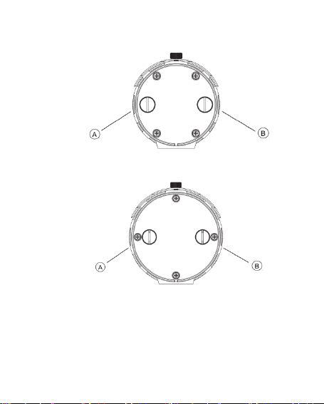
TVC-BIR6-MR(-P):
TVC-BIR6-HR(-P):
Figure 3: Camera zoom and focus
EN
adjustment
A. Focus; B. Zoom
9
Page 12

DE Abbildung 3: Zoom- und
q
p
ę
g
Fokuseinstellung der Kamera
A. Fokus; B. Zoom
ES Figura 3: Ajuste del zoom y del
enfoque de la cámara
A. Enfo
FR Figure 3 : Réglage du zoom et de la
mise au point de la caméra
A. Mise au
IT Figura 3: regolazione dello zoom e
della messa a fuoco della
telecamera
A. Messa a fuoco; B. Zoom
NL Afbeelding 3: Camerzoomfunctie en
scherpstelling
A. Focus; B. Zoom
PL Rysunek 3: regulacja powiększenia
i ostrości kamery
A. Ostrość; B. Powi
PT Figura 3: Ajuste do zoom e da
focagem da câmarat
A. Foca
10
ue; B. Zoom
oint ; B. Zoom
kszenie
em; B. Zoom
Page 13

RU Рис. 3. Настройка масштаба и
р
фокуса камеры
A. Фокусировка;
B. Масштаби
TR Şekil 3: Kamera zoom ve fokus
ayarı
A. Fokus; B. Zoom
11
ование
Page 14

EN
Overview
This is the TruVision Bullet IR Camera
Pocket Guide for models TVC-BIR6-MR(-P)
and TVC-BIR6-HR(-P). This guide describes
a standard installation.
The camera consists of the following:
Camera with power and video output
cables
Sunshield
Refer to the figures on pages 3, 6 and 9
when performing the camera setup
procedures.
EN 12
Page 15

Installation
When installing the camera, please use the
mounting bracket.
To install the camera:
1. Using the mount as a template, place it
level against the mounting surface and
mark the position of the mounting holes.
2. Following all local codes, drill and
prepare the mounting holes.
3. Securely fasten the mount to the
mounting surface with the appropriate
fasteners.
4. If needed, seal all mounting holes so that
no moisture can leak into the mounting
surface.
5. Screw the camera into the mounting
bracket. Ensure that the camera is firmly
attached to the bracket.
13 EN
Page 16

6. Connect a 75 ohm coaxial video cable to
the video cable, and connect a 12 VDC
or 24 VAC power supply to the power
cable.
7. Adjust the camera position and angle as
required.
8. If necessary, use a flat blade screwdriver
to adjust the zoom first, and then adjust
the focus (Figure 3 on page 9).
Specifications
Power supply 24 VAC/12 VDC
Current TVC-BIR6-MR(-P):
EN 14
180 mA (IR OFF)
590 mA (IR ON)
TVC-BIR6-HR(-P):
180 mA (IR OFF)
630 mA (IR ON)
Page 17

Power
consumption
Weight (net) TVC-BIR6-MR(-P):
Dimensions
(D × H × L)
15 EN
TVC-BIR6-MR(-P):
7.08 W max.
TVC-BIR6-HR(-P):
7.56 W max.
2.04 lb. (950 g)
TVC-BIR6-HR(-P):
2.53 lb. (1150 g)
TVC-BIR6-MR(-P):
2.99 x 7.09 x 7.47 in.
(76 x 180 x 190 mm)
TVC-BIR6-HR(-P):
3.5 x 7.56 x 8.09 in.
(88 x 192 x 206 mm)
Page 18

DE
Übersicht
Dies ist die Kurzanleitung für die TruVision
Bullet IR-Kamera, Modelle TVC-BIR6-MR(-P)
und TVC-BIR6-HR(-P). In diesem Handbuch
wird die Standardinstallation beschrieben.
Die Kamera umfasst folgende Elemente:
Kamera mit Netz- und
Videoausgabekabeln
Sonnenschutz
Ziehen Sie bei der Einrichtung der Kamera
die Abbildungen auf den Seiten 3, 6 und
9 zurate.
DE 16
Page 19

Installation
Verwenden Sie bei der Installation der
Kamera die Montagehalterung.
Die Kamera montieren:
1. Platzieren Sie die Halterung als Vorlage
waagerecht zur Montagefläche.
Markieren Sie die Position der
Montageöffnungen.
2. Bohren Sie unter Beachtung der örtlichen
Bestimmungen die Montageöffnungen
und bereiten Sie diese vor.
3. Befestigen Sie die Halterung mit den
geeigneten Befestigungselementen
sicher an der Montagefläche.
4. Versiegeln Sie gegebenenfalls sorgfältig
alle Montagebohrungen, sodass keine
Feuchtigkeit in die Montagefläche
eindringen kann.
17 DE
Page 20

5. Schrauben Sie die Kamera in die
Montagehalterung. Vergewissern Sie
sich, dass die Kamera fest in der
Halterung sitzt.
6. Schließen Sie ein Koaxial-Videokabel
(75 Ohm) an das Videokabel und ein
Netzteil (12 V DC oder 24 V AC) an das
Netzkabel an.
7. Passen Sie Position und Winkel der
Kamera nach Bedarf an.
8. Wenn erforderlich, verwenden Sie einen
Schlitzschraubendreher, um zuerst den
Zoom und dann den Fokus einzustellen
(siehe Abbildung 3 auf Seite 9).
Technische Daten
Netzteil 24 V AC/12 V DC
DE 18
Page 21

Stromaufnahme TVC-BIR6-MR(-P):
Leistungsaufnahme TVC-BIR6-MR(-P):
Nettogewicht TVC-BIR6-MR(-P):
Abmessungen
(D × H × L)
180 mA (IR AUS)
590 mA (IR EIN)
TVC-BIR6-HR(-P):
180 mA (IR AUS)
630 mA (IR EIN)
Max. 7,08 W
TVC-BIR6-HR(-P):
Max. 7,56 W
950 g
TVC-BIR6-HR(-P):
1.150 g
TVC-BIR6-MR(-P):
76 x 180 x 190 mm
TVC-BIR6-HR(-P):
88 x 192 x 206 mm
19 DE
Page 22

ES
Descripción general
Esta es la Guía de bolsillo de la cámara
TruVision Bullet IR de los modelos
TVC-BIR6-MR(-P) y TVC-BIR6-HR(-P). Esta
guía describe una instalación estándar.
La cámara consta de los siguientes
componentes:
Cámara con cables de alimentación y de
salida de vídeo
Protección solar
Consulte las siguientes figuras en las
páginas 3, 6 y 9 para realizar los
procedimientos de instalación de la cámara.
ES 20
Page 23

Instalación
Al instalar la cámara, utilice el soporte de
montaje.
Para instalar la cámara:
1. Utilizando la base como plantilla,
colóquela nivelada sobre la superficie de
montaje y marque la posición de los
orificios de montaje.
2. Siguiendo todas las normativas locales,
taladre y prepare los orificios de montaje.
3. Fije la base a la superficie de montaje
con las sujeciones adecuadas.
4. Si lo considera conveniente, selle todos
los orificios de montaje para impedir que
la humedad pueda penetrar por ellos.
5. Atornille la cámara al soporte de montaje.
Asegúrese de que la cámara está
firmemente sujeta al soporte.
21 ES
Page 24

6. Conecte un cable coaxial de vídeo de
75 ohmios al cable de vídeo y una fuente
de alimentación de 12 V CC o 24 V CA al
cable de alimentación.
7. Ajuste la posición y el ángulo de la
cámara como se requiere.
8. Si fuera necesario, utilice un
destornillador plano para ajustar primero
el zoom y luego el enfoque (Figura 3 en
la página 9).
Especificaciones
Fuente de
alimentación
ES 22
24 V CA/12 V CC
Page 25

Corriente TVC-BIR6-MR(-P):
180 mA (IR APAGADO)
590 mA (IR ENCENDIDO)
TVC-BIR6-HR(-P):
180 mA (IR apagado)
630 mA (IR encendido)
Consumo de
energía
TVC-BIR6-MR(-P):
7,08 W máx.
TVC-BIR6-HR(-P):
7,56 W máx.
Peso (neto) TVC-BIR6-MR(-P):
950 g
TVC-BIR6-HR(-P):
1.150 g
Dimensiones
(P x A x A)
TVC-BIR6-MR(-P):
76 x 180 x 190 mm
(2,99 x 7,09 x 7,47 pulg.)
TVC-BIR6-HR(-P):
88 x 192 x 206 mm
(3,5 x 7,56 x 8,09 pulg.)
23 ES
Page 26

FR
Présentation
Ceci est le guide de poche de la caméra IR
TruVision Bullet pour les modèles
TVC-BIR6-MR(-P) et TVC-BIR6-HR(-P). Il
décrit une installation standard.
La caméra se compose des éléments
suivants :
Caméra avec câble d'alimentation et de
sortie vidéo
Pare-soleil
Consultez les figures des pages 3, 6 et 9 lors
de l'installation de la caméra.
FR 24
Page 27

Installation
Lors de l'installation de la caméra, utilisez le
support de montage.
Pour installer la caméra :
1. Utilisez le support comme modèle et
placez-le droit contre la surface de
montage, puis marquez la position des
orifices de montage.
2. En respectant la réglementation locale,
percez et préparez les orifices de
montage.
3. Fixez le support à la surface de montage
à l'aide des chevilles appropriées.
4. Le cas échéant, veillez à boucher tous
les orifices de montage, afin d'éviter toute
infiltration à l'intérieur de la surface.
25 FR
Page 28

5. Fixez la caméra au support de montage.
Assurez-vous que la caméra est
fermement fixée au support.
6. Connectez un câble vidéo coaxial
75 ohms au câble vidéo et reliez une
alimentation 12 V c.c. ou 24 V c.a. au
câble d'alimentation.
7. Réglez, si nécessaire, la position et
l'angle de la caméra.
8. Si nécessaire, utilisez un tournevis à
lame plate pour régler d'abord le zoom,
puis réglez la mise au point (Figure 3 à la
page 9).
Spécifications
Alimentation
électrique
FR 26
24 V c.a./12 V c.c
Page 29

Courant TVC-BIR6-MR(-P) :
Consommation TVC-BIR6-MR(-P) :
Poids (net) TVC-BIR6-MR(-P) :
Dimensions
(P × H × L)
180 mA (IR DÉSACTIVÉ)
590 mA (IR ACTIVÉ)
TVC-BIR6-HR(-P) :
180 mA (IR DÉSACTIVÉ)
630 mA (IR ACTIVÉ)
7,08 W max.
TVC-BIR6-HR(-P) :
7,56 W max.
950 g
TVC-BIR6-HR(-P) :
1 150 g
TVC-BIR6-MR(-P) :
76 x 180 x 190 mm
TVC-BIR6-HR(-P) :
88 x 192 x 206 mm
27 FR
Page 30

IT
Panoramica
La presente è la guida rapida della
telecamera TruVision Bullet IR per i modelli
TVC-BIR6-MR(-P) e TVC-BIR6-HR(-P), in cui
viene descritta l'installazione standard.
La telecamera è formata dai seguenti
componenti:
Telecamera con cavi di uscita video e
alimentazione
Parasole
Durante le procedure di installazione, fare
riferimento alle figure alle pagine 3, 6 e 9.
IT 28
Page 31

Installazione
Quando si installa la telecamera, utilizzare il
supporto di montaggio.
Installazione della telecamera:
1. Utilizzando il supporto come modello,
posizionarlo contro la superficie di
montaggio e contrassegnare la posizione
dei fori di montaggio.
2. Praticare i fori di montaggio
conformemente alle normative locali.
3. Fissare saldamente il supporto alla
superficie di montaggio utilizzando i
dispositivi di fissaggio appropriati.
4. Se necessario, sigillare tutti i fori di
montaggio in modo che non siano
possibili perdite di liquidi sulla superficie
di montaggio.
29 IT
Page 32

5. Avvitare la telecamera al supporto di
montaggio. Accertarsi che sia
saldamente fissata al supporto.
6. Collegare un cavo video coassiale da
75 ohm al cavo video e un alimentatore
da 12 Vcc o 24 Vca al cavo di
alimentazione.
7. Regolare la posizione e l'angolatura della
telecamera secondo necessità.
8. Se necessario, utilizzare un cacciavite a
punta piatta per regolare prima lo zoom e
quindi la messa a fuoco (Figura 3 a
pagina 9).
Specifiche tecniche
Alimentazione 24 Vca/12 Vcc
IT 30
Page 33

Corrente TVC-BIR6-MR(-P):
Consumo TVC-BIR6-MR(-P):
Peso (netto) TVC-BIR6-MR(-P):
Dimensioni
(P × A × L)
180 mA (IR SPENTO)
590 mA (IR ACCESO)
TVC-BIR6-HR(-P):
180 mA (IR SPENTO)
630 mA (IR ACCESO)
7,08 W max.
TVC-BIR6-HR(-P):
7,56 W max.
950 g
TVC-BIR6-HR(-P):
1150 g
TVC-BIR6-MR(-P):
76 x 180 x 190 mm
TVC-BIR6-HR(-P):
88 x 192 x 206 mm
31 IT
Page 34

NL
Overzicht
Dit is de TruVision Bullet IR Camera
Beknopte handleiding voor de modellen
TVC-BIR6-MR(-P) en TVC-BIR6-HR(-P). Dit
document beschrijft een standaardinstallatie.
De camera bestaat uit de volgende
onderdelen:
Camera met voedings- en video-
uitgangskabels
Zonwering
Raadpleeg de afbeeldingen op pagina's 3, 6
en 9 tijdens het uitvoeren van de
installatieprocedures voor de camera.
NL 32
Page 35

Installatie
Gebruik de montagesteun tijdens het
installeren van de camera.
U installeert de camera als volgt:
1. Gebruik de bevestiging als sjabloon,
plaats deze waterpas tegen het
montageoppervlak en markeer de positie
van de bevestigingsgaten.
2. Boor en prepareer volgens alle
plaatselijke voorschriften de
bevestigingsgaten.
3. Maak de bevestiging stevig vast aan het
montageoppervlak met het juiste
bevestigingsmateriaal.
4. Dicht indien nodig alle bevestigingsgaten
goed af zodat er geen vocht in het
montageoppervlak kan doordringen.
33 NL
Page 36

5. Schroef de camera op de
montagebeugel. Controleer of de camera
stevig vastzit aan de beugel.
6. Sluit een 75 ohm coaxiale videokabel aan
op de videokabel van de camera en sluit
een 12 VDC of 24 VAC voeding aan op
de voedingskabel.
7. Pas de camerapositie en de beeldhoek
aan naar wens.
8. Gebruik eventueel een schroevendraaier
met een platte kop om eerst de
zoomstand en vervolgens de
scherpstelling in te stellen (Afbeelding 3
op pagina 9).
Specificaties
Voedingseenheid 24 VAC / 12 VDC
NL 34
Page 37

Spanning TVC-BIR6-MR(-P):
Stroomverbruik TVC-BIR6-MR(-P):
Gewicht (netto) TVC-BIR6-MR(-P):
Afmetingen
(D × H × L)
35 NL
180 mA (IR UIT)
590 mA (IR AAN)
TVC-BIR6-HR(-P):
180 mA (IR UIT)
630 mA (IR AAN)
7,08 W max.
TVC-BIR6-HR(-P):
7,56 W max.
950 g (2,04 lb.)
TVC-BIR6-HR(-P):
1150 g (2,53 lb.)
TVC-BIR6-MR(-P):
76 x 180 x 190 mm
(2,99 x 7,09 x 7,47 inch)
TVC-BIR6-HR(-P):
88 x 192 x 206 mm
(3,5 x 7,56 x 8,09 inch )
Page 38

PL
Informacje podstawowe
Niniejszy dokument to kieszonkowy
przewodnik dla modeli TVC-BIR6-MR(-P) i
TVC-BIR6-HR(-P) kamery TruVision Bullet
IR. Przewodnik ten opisuje procedurę
standardowej instalacji.
Kamera składa się z następujących
elementów:
Kamera z przewodem zasilającym i
przewodem wyjścia wideo
Osłona przeciwsłoneczna
Aby przeprowadzić konfigurację kamery,
zapoznaj się z rysunkami na stronach 3, 6 i 9.
PL 36
Page 39

Instalacja
Podczas montażu kamery należy użyć
uchwytu mocującego.
Aby zainstalować kamerę:
1. Korzystając z uchwytu mocującego jako
wzoru, umieść go poziomo przy
powierzchni montażowej i zaznacz
pozycję otworów montażowych.
2. Zgodnie z lokalnymi przepisami wywierć i
przygotuj otwory montażowe.
3. Przymocuj uchwyt do powierzchni
montażowej za pomocą odpowiednich
wkrętów.
4. W razie potrzeby uszczelnij odpowiednio
wszystkie otwory montażowe, żeby
zapobiec dostawaniu się wilgoci do
wnętrza powierzchni montażowej.
37 PL
Page 40

5. Przykręć kamerę do uchwytu
mocującego. Sprawdź, czy kamera jest
mocno przymocowana do uchwytu.
6. Podłącz 75 omowy koncentryczny kabel
wideo do kabla wideo oraz zasilacz prądu
stałego 12 VDC lub prądu zmiennego
24 VAC do kabla zasilania.
7. Jeśli to konieczne, dopasuj położenie
oraz kąt ustawienia kamery.
8. Jeżeli to konieczne, za pomocą płaskiego
śrubokręta dokonaj najpierw regulacji
powiększenia, a następnie ostrości
(rysunek 3 na stronie 9).
Dane techniczne
Zasilacz 24 VAC/12 VDC
PL 38
Page 41

Natężenie
Zużycie
energii
Waga (netto)
39 PL
TVC-BIR6-MR(-P):
180 mA (oświetlenie
podczerwieni
WYŁĄCZONE)
590 mA (oświetlenie
podczerwieni WŁĄCZONE)
TVC-BIR6-HR(-P):
180 mA (oświetlenie
podczerwieni
WYŁĄCZONE)
630 mA (oświetlenie
podczerwieni WŁĄCZONE)
TVC-BIR6-MR(-P):
Maks. 7,08 W
TVC-BIR6-HR(-P):
Maks. 7,56 W
TVC-BIR6-MR(-P):
950 g
TVC-BIR6-HR(-P):
1150 g
Page 42

Wymiary
(G × W × D)
TVC-BIR6-MR(-P):
76 x 180 x 190 mm
TVC-BIR6-HR(-P):
88 x 192 x 206 mm
PL 40
Page 43

PT
Descrição geral
Este é o Guia Rápido da Câmara TruVision
Bullet IR, modelos TVC-BIR6-MR(-P) e
TVC-BIR6-HR(-P). Este guia descreve uma
instalação standard.
A câmara inclui os seguintes elementos:
Câmara com cabos de alimentação e
saída de vídeo
Protector de sol
Consulte as figuras nas páginas 3, 6 e 9 ao
realizar procedimentos de configuração da
câmara.
41 PT
Page 44

Instalação
Ao instalar a câmara, utilize o suporte de
montagem.
Para instalar a câmara:
1. Utilizando o suporte como modelo,
coloque-o nivelado na superfície de
montagem e marque a posição dos
orifícios de montagem.
2. Cumprindo todos os códigos locais, abra
e prepare os orifícios de montagem.
3. Fixe o suporte com segurança à
superfície de montagem, utilizando os
parafusos correctos.
4. Se necessário, proceda à vedação de
todos os orifícios de montagem para que
nenhuma humidade possa penetrar na
superfície de montagem.
PT 42
Page 45

5. Aparafuse a câmara ao suporte de
montagem. Certifique-se de que a
câmara está firmemente afixada ao
suporte.
6. Ligue um cabo de vídeo coaxial de
75 ohm ao cabo de vídeo, e ligue uma
fonte de alimentação de 12 VDC ou
24 VAC ao cabo de alimentação.
7. Regule a posição e o ângulo da câmara,
conforme necessário.
8. Se necessário, utilize uma chave de
parafusos de lâmina chata para regular
primeiro o zoom e depois a focagem
(Figura 3 na página 9).
Especificações
Fonte de
alimentação
43 PT
24 VAC/12 VDC
Page 46

Corrente TVC-BIR6-MR(-P):
180 mA (IR DESLIGADO)
590 mA (IR LIGADO)
TVC-BIR6-HR(-P):
180 mA (IR DESLIGADO)
630 mA (IR LIGADO)
Consumo de
energia
TVC-BIR6-MR(-P):
7,08 W máx.
TVC-BIR6-HR(-P):
7,56 W máx.
Peso (líquido) TVC-BIR6-MR(-P):
950 g (2,04 lb)
TVC-BIR6-HR(-P):
1150 g (2,53 lb)
Dimensions
(P × A × C)
TVC-BIR6-MR(-P):
76 x 180 x 190 mm
(2,99 x 7,09 x 7,47 pol)
TVC-BIR6-HR(-P):
88 x 192 x 206 mm
(3,5 x 7,56 x 8,09 pol)
PT 44
Page 47

RU
Обзор
Этот документ представляет собой
карманное руководство камеры TruVision
Bullet IR для моделей TVC-BIR6-MR(-P) и
TVC-BIR6-HR(-P). В данном руководстве
описана стандартная установка.
Камера состоит из перечисленных ниже
компонентов.
Камера с кабелями питания и
видеовыхода
Защита от солнца
Для установки камеры используйте
рисунки, приведенные на стр. 3, 6 и 9.
45 RU
Page 48

Установка
При установке камеры используйте
монтажный кронштейн.
Установка камеры.
1. Используя основу в качестве шаблона,
поместите камеру на уровне
монтажной поверхности и отметьте
места, где должны быть расположены
крепежные отверстия.
2. Соблюдая местные нормативы,
просверлите и подготовьте крепежные
отверстия.
3. Закрепите основу на монтажной
поверхности с помощью
соответствующего крепежа.
4. При необходимости загерметизируйте
все
монтажные отверстия, чтобы
избежать попадания влаги вглубь
несущей поверхности.
RU 46
Page 49

5. Закрепите камеру на монтажном
кронштейне. Убедитесь в том, что
камера надежно закреплена на
кронштейне.
6. Подсоедините коаксиальный
видеокабель (на 75 Ом) к
видеокабелю, а источник питания (на
12 В постоянного тока или 24 В
переменного тока) к кабелю питания.
7. Выберите нужное положение камеры и
требуемый угол обзора.
8. При необходимости воспользуйтесь
отверткой с
сначала настроить масштаб, а затем
фокус (рис. 3 на стр. 9).
плоским лезвием, чтобы
47 RU
Page 50

Характеристики
Источник
питания
Ток TVC-BIR6-MR(-P):
Потребля
емая
мощность
RU 48
24 В переменного тока/12 В
постоянного тока
180 мА (инфракрасные
светодиоды ВЫКЛЮЧЕНЫ)
590 мА (инфракрасные
светодиоды ВКЛЮЧЕНЫ)
TVC-BIR6-HR(-P):
180 мА (инфракрасные
светодиоды ВЫКЛЮЧЕНЫ)
630 мА (инфракрасные
светодиоды ВКЛЮЧЕНЫ)
TVC-BIR6-MR(-P):
7,08 Вт (макс.)
TVC-BIR6-HR(-P):
7,56 Вт (макс.)
Page 51

Вес нетто TVC-BIR6-MR(-P):
950 г (2,04 фунта)
TVC-BIR6-HR(-P):
1150 г (2,53 фунта)
Габариты
(В × Г × Д)
TVC-BIR6-MR(-P):
76 x 180 x 190 мм
(2,99 x 7,09 x 7,47 дюйма)
TVC-BIR6-HR(-P):
88 x 192 x 206 мм
(3,5 x 7,56 x 8,09 дюйма)
49 RU
Page 52

TR
Genel Bakış
Bu, TVC-BIR6-MR(-P) ve TVC-BIR6-HR(-P)
modelleri için, TruVision Bullet IR Kamera
Cep Kılavuzudur. Bu kılavuz, standart
kurulumu anlatmaktadır.
Kamera aşağıdakilerden oluşur:
Güç ve video çıkış kablolu kamera
Güneşlik
Kamera ayar prosedürlerini gerçekleştirirken,
3, 6 ve 9. sayfadaki resimlere bakın.
Kurulum
Kamerayı kurarken, lütfen montaj aparatını
kullanın.
TR 50
Page 53

Kamerayı kurmak için:
1. Montaj parçasını şablon olarak kullanmak
suretiyle, onu montaj yüzeyine karşı aynı
seviyeye yerleştirin ve montaj deliklerinin
konumunu işaretleyin.
2. Tüm yerel kodları takip ederek, matkapla
delin ve montaj deliklerini hazırlayın.
3. Montaj parçasını uygun bağlantı
elemanları ile montaj yüzeyine sağlam bir
şekilde bağlayın.
4. Gerekirse, montaj yüzeyine nem
sızmayacak şekilde tüm montaj deliklerini
yalıtın.
5. Kamerayı montaj aparatına vidalayın.
Kameranın bağlantı aparatına sıkıca
tutturulduğundan emin olun.
6. 75 ohm değerindeki koaksiyel görüntü
kablosunu görüntü kablosuna, 12 VDC
veya 24 VAC güç kaynağını da güç
kablosuna bağlayın.
51 TR
Page 54

7. Kamera konumunu ve açısını gereken
şekilde ayarlayın.
8. Gerekirse, önce zoomu ayarlamak için
düz uçlu bir tornavida kullanın, sonra
fokusu ayarlayın (Bkz. 9. sayfadaki
Şekil 3).
Teknik özellikler
Güç kaynağı 24 VAC/12 VDC
Akım TVC-BIR6-MR(-P):
TR 52
180 mA (IR KAPALI)
590 mA (IR AÇIK)
TVC-BIR6-HR(-P):
180 mA (IR KAPALI)
630 mA (IR AÇIK)
Page 55

Güç tüketimi TVC-BIR6-MR(-P):
7,08 W maks.
TVC-BIR6-HR(-P):
7,56 W maks.
Ağırlık (net) TVC-BIR6-MR(-P):
2,04 lb. (950 g)
TVC-BIR6-HR(-P):
2,53 lb. (1.150 g)
Boyutlar
(D × Y × U)
TVC-BIR6-MR(-P):
2,99 x 7,09 x 7,47 in.
(76 x 180 x 190 mm)
TVC-BIR6-HR(-P):
3,5 x 7,56 x 8,09 in.
(88 x 192 x 206 mm)
53 TR
Page 56

Legal / Rechtliche Angaben /
Información legal /
Informations légales / Note
legali / Juridisch /
Informacje prawne /
Informação legal /
Нормативно-правовые
аспекты / Yasal
Copyright:
© 2012 UTC Fire & Security. All rights reserved.
Trademarks and patents:
Interlogix and TruVision brand and log o are trademarks of
UTC Fire & Security.
Other trade names used in this docum ent may be tradem arks or
registered trademarks of the manufacturers or vendors of the respective
products.
TR 54
Page 57

Manufacturer:
UTC Fire & Security Americas Corporation, Inc.
2955 Red Hill Avenue, Costa Mesa, CA 92626- 5923, USA
Authorized EU manufacturing representat ive:
UTC Fire & Security B.V.
Kelvinstraat 7, 6003 DH Weert, The Netherl ands
Certification:
FCC compliance: Class B
This equipment has been tested and foun d to comply with the limits for a
Class B digital device, pursuant to part 15 of the FCC Rules. These limits
are designed to provide reasonable protection against harmful
interference in a residential installation. This equipment generates, uses,
and can radiate radio frequency energ y and, if not installed and used in
accordance with the instructions, m ay cause harmful interference to radio
communications.
Changes or modifications not expressl y approved by the par ty
responsible for compliance could void the user’s author ity to operate the
equipment.
European Union directives:
12004/108/CE (EMC directive): Hereby, UTC Fire & Security declares
that this device is in compliance with the essential requirements and
other relevant provisions of Directive 2004/108/EC.
N4131
55 TR
Page 58

2002/96/CE (WEEE directive): Products marked
with this symbol cannot be disposed of as
unsorted municipal waste in the European Union.
For proper recycling, return this product t o your
local supplier upon the purchase of eq uivalent
new equipment, or dispose of it at designat ed
collection points. For more inform ation see:
www.recyclethis.info.
Contact information:
For contact information, see www.interlogix.com or
www.utcfssecurityproducts.eu.
TR 56
Page 59

Page 60

 Loading...