

Page 1

TruVision High Resolution TVI
Box Camera TVC
-2401 /
TVC
P/N 1073165-EN • REV A • ISS 04APR16
-4401 Installation Guide
Page 2

Page 3

Content
Product overview 2
Camera description 3
Installation 5
Programming 7
Setup menu 9
Specifications 10
Legal and regulatory information 10
Installation Guide 1
Page 4
Product overview
This is the Installation Guide for TruVision High
Resolution TV I Box Camera TVC-2401/TVC-4401.
This guide describes a standard installation.
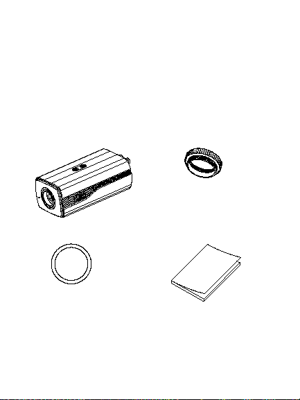
Package contents
Box camera
Lens ring
2 Installation Guide
CS adaptor
Quick guide
Page 5
WEEE disposal
CD
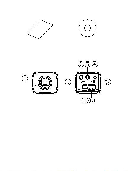
Camera description
1. Lens mounting ring
2. CVBS output
3. TVI output
4. Menu button
5. Power LED indicator
Installation Guide 3
Page 6

6. GND
1
2
7. 12 VDC / 24 VAC
8. Alarm, RS-485, D/N port
1. Lock screw
2. Auto-iris drive interface
Auto iris connector
The auto iris connector is composed of four square
pins as shown below. Damp+, Damp-, Drive+ and
Drive- pins are used in DC driven mode.
4 Installation Guide
Page 7

No. DC
1 Damp-
2 Damp+
3 Driver-
4 Driver+
Installation
Refer to the instructions that came with the lens you
purchased for complete lens installation instructions.
The camera automatically detects the type of lens
used.
Note: For optimal performance, an auto iris lens is
recommended.
To attach the lens:
1. If a C-mount lens is used, the supplied CS
adaptor must be fitted to the lens mounting ring
or the sensor/filter may be damaged
2. Rotate the lens clockwise onto the lens
mounting ring of the camera.
Installation Guide 5
Page 8

3. Connect the lens auto iris wire to the auto iris
connector of the camera.
To mount the camera:
1. Attach the camera to a mounting bracket using
appropriate fasteners or install the camera in
an appropriate outdoor housing.
2. Adjust the camera to get an optimum angle.
3. Tighten the screw to secure the camera to the
bracket, if required.
To finish the installation:
1. Using a 75-ohm coaxial video cable, connect
the camera TVI video output to a TVI DVR.
6 Installation Guide
Page 9

2. Connect the service monitor CVBS connector
to the camera CVBS output, if required. Please
refer to the Programming section for more
information.
3. Power the camera with a power supply. Please
mind the polarity of 12 VDC connections.
24 VAC connections are not polarity sensitive.
4. Finish the installation b y adjusting zoom and
focus to get a clear picture.
Programming
Program using a TVI output
Once the camera hardware has been installed, you
can configure the camera settings on the TVI DVR.
Installation Guide 7
Page 10

Please select the PT Z protocol as TruVision Coax
and click the menu button to call up the camera
menu. For more details, please see the TVI DVR
user manual.
The camera has CVBS and TVI dual video outputs.
When the WDR feature is enabled via the OSD, the
CVBS output will be blocked.
8 Installation Guide
Page 11

Setup menu
Installation Guide 9
Page 12

Specifications
Power supply 24 VAC / 12 VDC
Current 1 A max.
Power
12 W max.
consumption
Weight (net) 0.83 lb. (378 g)
Dimensions 2.7 x 2.3 x 5.85 in.
(69.2 × 57.3 × 148.7 mm)
Legal and regulatory information
Copyright:
© 2016 United Technologies Corporation,
Interlogix is part of UTC Climate, Controls & Security, a unit of
United Technologies Corporation. All rights reserved.
Trademarks and patents:
Trade names used in this document may be trademarks or
registered trademarks of the manufacturers or vendors of the
respective products.
10 Installation Guide
Page 13

Manufacturer:
erated in a commercial environment. This equipment generates,
Interlogix
2955 Red Hill Avenue, Costa Mesa, CA 92626-5923, USA
Authorized EU manufacturing representative:
UTC Fire & Security B.V.
Kelvinstraat 7, 6003 DH Weert, The Netherlands
Certification:
FCC compliance: Class A
Class A: This equipment has been tested and found to comply
with the limits for a Class A digital device, pursuant to part 15 of
the FCC Rules. These limits are designed to provide reasonable
protection against harmful interference when the equipment is
op
uses, and can radiate radio frequency energy and, if not installed
and used in accordance with the instruction manual, may cause
harmful interference to radio communications. Operation of this
equipment in a residential area is likely to cause harmful
interference in which case the user will be required to correct the
interference at his own expense.
ACMA compliance
Notice! This is a Class A product. In a domestic environment this
product may cause radio interference in which case the user may
be required to take adequate measures.
Canada
This Class A digital apparatus complies with Canadian ICES-003.
Cet appareil numérique de la classe A est conforme à la norme
NMB-0330 du Canada.
Installation Guide 11
Page 14

European Union directives:
12004/108/CE (EMC directive): Hereby, UT C Fire & Security declares
that this device is in compli ance with the essential requirements and
other relevant provisions of Directive 2004/108/EC.
2012/19/EU (WEEE directive): Products marked
with this symbol cannot be disposed of as
unsorted municipal waste in the European Union.
For proper recycling, return this product t o your
local supplier upon the purc hase of equivalent
new equipment, or dispose of it at designated
collection points. For more i nformation see:
www.recyclethis.info.
Contact information:
For contact information, see www.interlogix.com or
www.utcfssecurityproducts.eu.
12 Installation Guide
Page 15

 Loading...