

Interlogix TVB-5304, TVB-5302, TVB-5305, TVB-5303, TVB-5306 Installation Manual
...
TruVision
Series 3 IP
Camera Installation
Guide
P/N 1073188-EN • REV E • ISS 22SEP17
Copyright
© 2017 United Technologies Corporation.
Interlogix is part of UTC Climate, Controls & Security, a
unit of United Technologies Corporation. All rights
reserved.
Trademarks and
patents
Trade names used in this document may be trademarks
or registered trademarks of the manufacturers or
vendors of the respective products.
Manufacturer
Interlogix
2955 Red Hill Avenue, Costa Mesa, CA 92626-5923,
USA
Authorized EU manufacturing representative:
UTC Fire & Security B.V.
Kelvinstraat 7, 6003 DH Weert, The Netherlands
Certification
FCC compliance
Class A: This equipment has been tested and found to
comply with the limits for a Class A digital device,
pursuant to part 15 of the FCC Rules. These limits are
designed to provide reasonable protection against
harmful interference when the equipment is operated in
a commercial environment. This equipment generates,
uses, and can radiate radio frequency energy and, if not
installed and used in accordance with the instruction
manual, may cause harmful interference to radio
communications. Operation of this equipment in a
residential area is likely to cause harmful interference in
which case the user will be required to correct the
interference at his own expense.
FCC conditions
This device complies with Part 15 of the FCC Rules.
Operation is subject to the following two conditions:
(1) This device may not cause harmful interference.
(2) This Device must accept any interference received,
including interference that may cause undesired
operation.
ACMA compliance
Notice! This is a Class A product. In a domestic
environment this product may cause radio interference
in which case the user may be required to take
adequate measures.
Canada
This Class A digital apparatus complies with CAN
ICES-003 (A)/NMB-3 (A).
Cet appareil numérique de la classe A est conforme à
la norme CAN ICES-003 (A)/NMB-3 (A).
European Union
directives
This product and - if applicable - the supplied
accessories too are marked with "CE" and comply
therefore with the applicable harmonized European
standards listed under the EMC Directive 2014/30/EU,
the RoHS Directive 2011/65/EU.
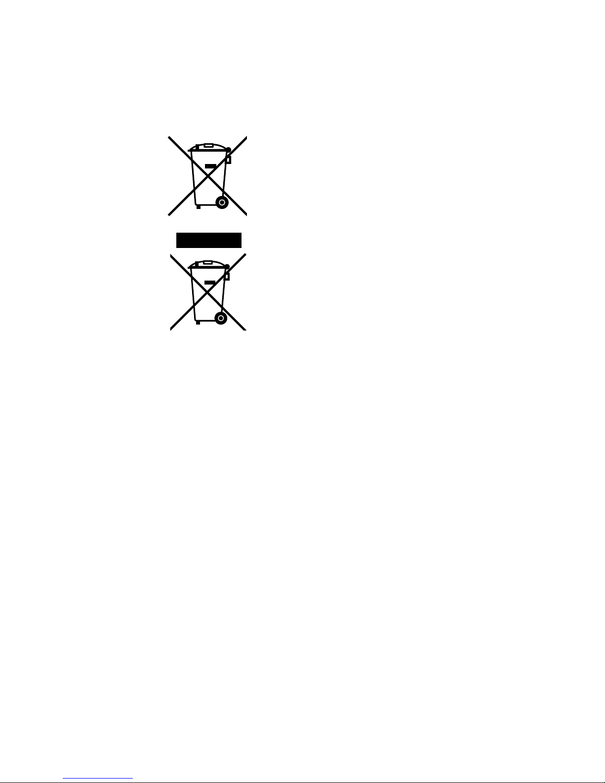
2012/19/EU (WEEE directive): Products marked with
this symbol cannot be disposed of as unsorted
municipal waste in the European Union. For proper
recycling, return this product to your local supplier upon
the purchase of equivalent new equipment, or dispose
of it at designated collection points. For more
information see: www.recyclethis.info
2013/56/EU and 2006/66/EC (battery directive): This
product contains a battery that cannot be disposed of
as unsorted municipal waste in the European Union.
See the product documentation for specific battery
information. The battery is marked with this symbol,
which may include lettering to indicate cadmium (Cd),
lead (Pb), or mercury (Hg). For proper recycling, return
the battery to your supplier or to a designated collection
point. For more information see: www.recyclethis.info.
Contact information
For contact information, see www.interlogix.com or
www.utcfssecurityproducts.eu.


Installation Guide 1
Content
Introduction 1
Product overview 1
Installation 3
Installation environment 3
Package contents 4
Cable requirements 20
Camera description 20
Setting up the camera 28
Accessing the SD card 28
Mounting the IP fixed lens bullet camera 29
Mounting the IP VF lens bullet camera and the IP motorized
lens bullet camera (without the supplied back box) 30
Mounting the IP VF lens dome camera and IP motorized lens
dome camera 36
Mounting the IP fixed lens dome camera 41
Mounting the IP wedge dome camera 45
Mounting the IP turret camera 48
Using the camera with a recorder 53
Using the camera with TruVision Navigator 53
Specifications 54
TruVision IP fixed lens bullet cameras 54
TruVision IP VF lens bullet cameras 54
TruVision IP motorized lens bullet cameras 55
TruVision IP VF lens dome cameras 55
TruVision IP motorized lens dome cameras 56

2 Installation Guide
TruVision IP fixed lens dome 57
TruVision IP wedge cameras 57
TruVision IP turret cameras 58
Pin definitions 59

Installation Guide 1
Introduction
Product overview
This is the installation guide for TruVision Series 3 IP camera
models:
IP fixed lens bullet camera:
TVB-5301 (2MPX Bullet, 4 mm lens)
TVB-5302 (4MPX Bullet, 4 mm lens)
IP VF lens bullet camera:
TVB-5303 (2MPX Bullet, 2.8 to 12 mm VF lens)
TVB-5304 (4MPX Bullet, 2.8 to 12 mm VF lens)
IP motorized lens bullet camera:
TVB-5305 (2MPX Bullet, 2.8-12 mm VF motorized lens)
TVB-5306 (4MPX Bullet, 2.8-12 mm VF motorized lens)
IP fixed lens dome camera:
TVD-5301 (2MPX Plastic Dome, 2.8 mm lens)
TVD-5302 (4MPX Plastic Dome, 2.8 mm lens)
IP VF lens dome camera:
TVD-5303 (2MPX VF Dome)
TVD-5304 (4MPX VF Dome)

2 Installation Guide
IP motorized lens dome camera:
TVD-5305 (2MPX Dome, 2.8-12 mm VF Motorized lens)
TVD-5306 (4MPX Dome, 2.8-12 mm VF Motorized lens)
IP wedge camera:
TVW-5301 (2MPX Wedge, 2.0 mm lens, Gray)
TVW-5302 (2MPX Wedge, 2.8 mm lens, Gray)
TVW-5303 (2MPX Wedge, 2.8 mm lens, White)
TVW-5304 (2MPX Wedge, 2.8 mm lens, Black)
TVW-5305 (4MPX Wedge, 2.8 mm lens, Gray)
IP turret camera:
TVT-5301 (2MPX Turret, 2.8 mm lens, Gray)
TVT-5302 (2MPX Turret, 2.8 mm lens, White)
TVT-5303 (2MPX Turret, 2.8 mm lens, Black)
TVT-5304 (4MPX Turret, 2.8 mm lens, Gray)
TVT-5305 (4MPX Turret, 2.8 mm lens, White)
TVT-5306 (4MPX Turret, 2.8 mm lens, Black)
TVT-5307 (4MPX Turret, 4.0 mm lens, White)

Installation Guide 3
Installation
This section provides information on how to install the
cameras.
Installation environment
When installing your product, consider these factors:
• Electrical: Install electrical wiring carefully. It should be
done by qualified service personnel. Always use a proper
PoE switch or a 12 VDC UL listed Class 2 or CE certified
power supply to power the camera. Do not overload the
power cord or adapter.
• Ventilation: Ensure that the location planned for the
installation of the camera is well ventilated.
• Temperature: Do not operate the camera beyond the
specified temperature, humidity or power source ratings.
The operating temperature of the camera is between -30
to +60°C (-22 to 140°F). Humidity is below 90%.
• Moisture: Do not expose the camera to rain or moisture,
or try to operate it in wet areas. Turn the power off
immediately if the camera is wet and ask a qualified
service person for servicing. Moisture can damage the
camera and also create the danger of electric shock.
• Servicing: Do not attempt to service this camera
yourself. Any attempt to dismantle this product will
invalidate the warranty and may also result in serious
injury. Refer all servicing to qualified service personnel.
• Cleaning: Do not touch the sensor modules with fingers.
If cleaning is necessary, use a clean cloth with some
ethanol and wipe the camera gently. If the camera will not
4 Installation Guide
be used for an extended period of time, put on the lens
cap to protect the sensors from dirt.
Package contents
Check the package and contents for visible damage. If any
components are damaged or missing, do not attempt to use
the unit; contact the supplier immediately. If the unit is
returned, it must be shipped back in its original packaging.
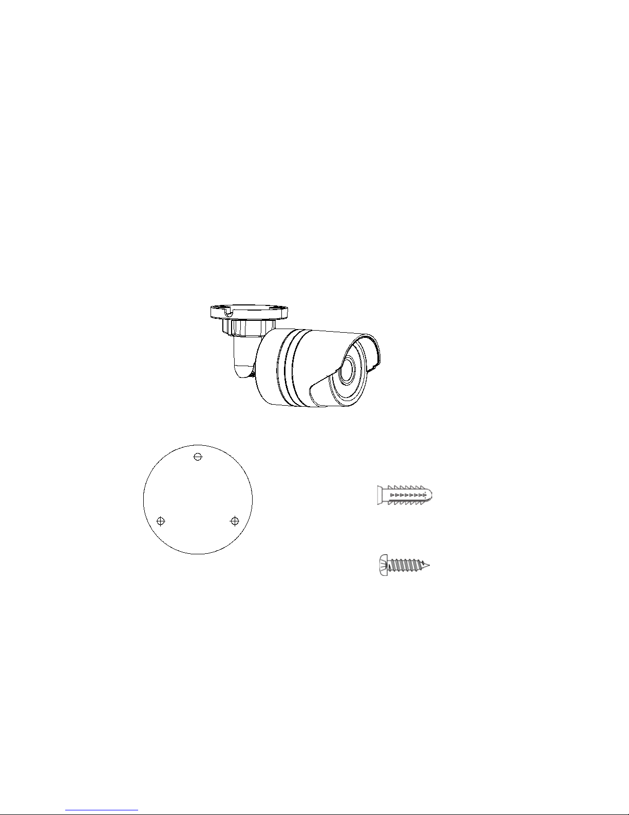
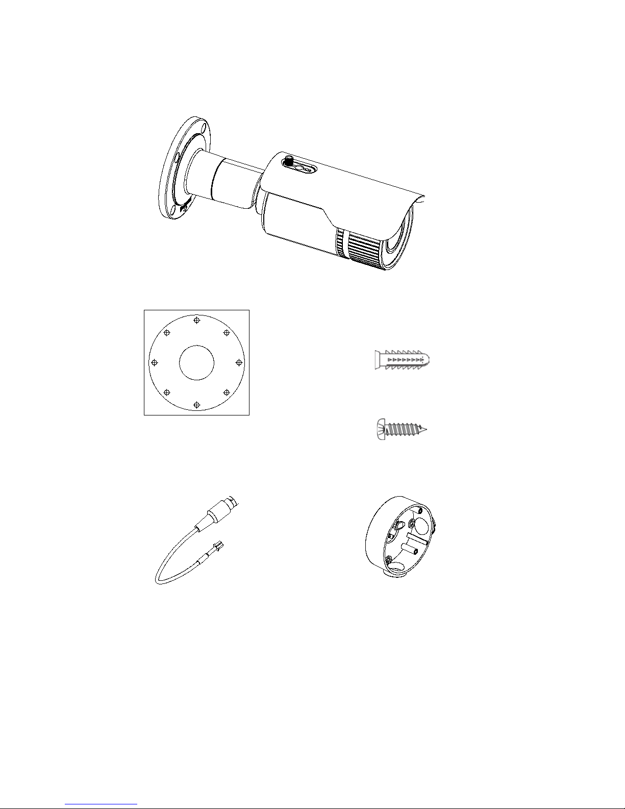
IP fixed lens bullet camera
Camera:
Drill template:
Screws:
Drywall anchor
7.5 × 24.5 mm (3 pcs)
Screw
M4 × 25 mm (3 pcs)
Drill Template
Screw hole All: for integrative bracket
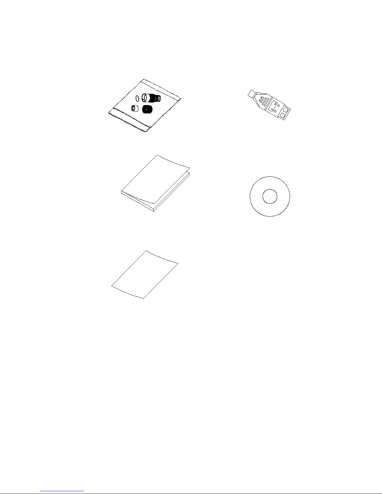
Installation Guide 5
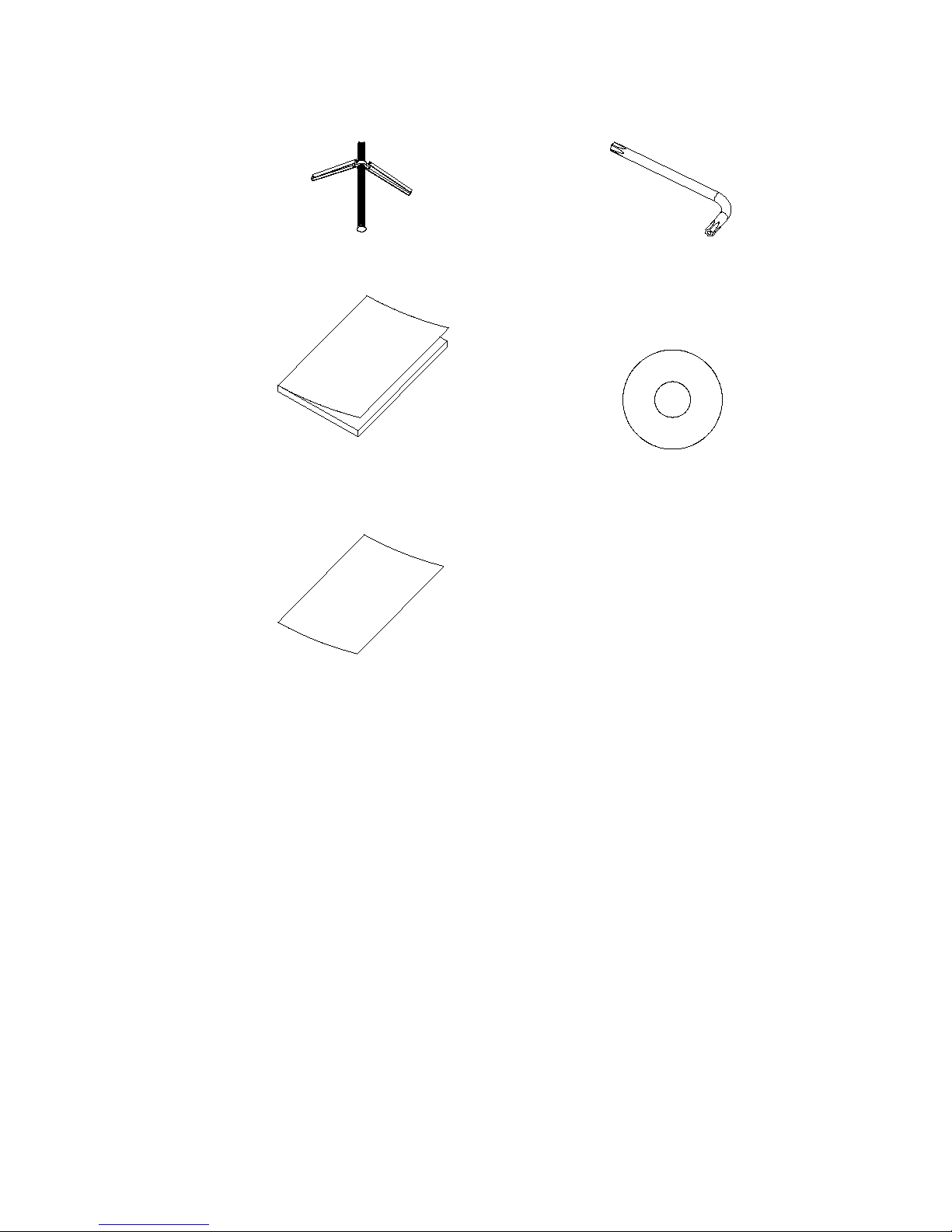
Water joint: Provides water
resistance to network cable
connector.
12 VDC connector:
Two terminal connector
with positive and
negative indicators.
Installation manual:
CD with manuals and
TruVision Device
Manager:
Equipment and Battery
Disposal sheets:
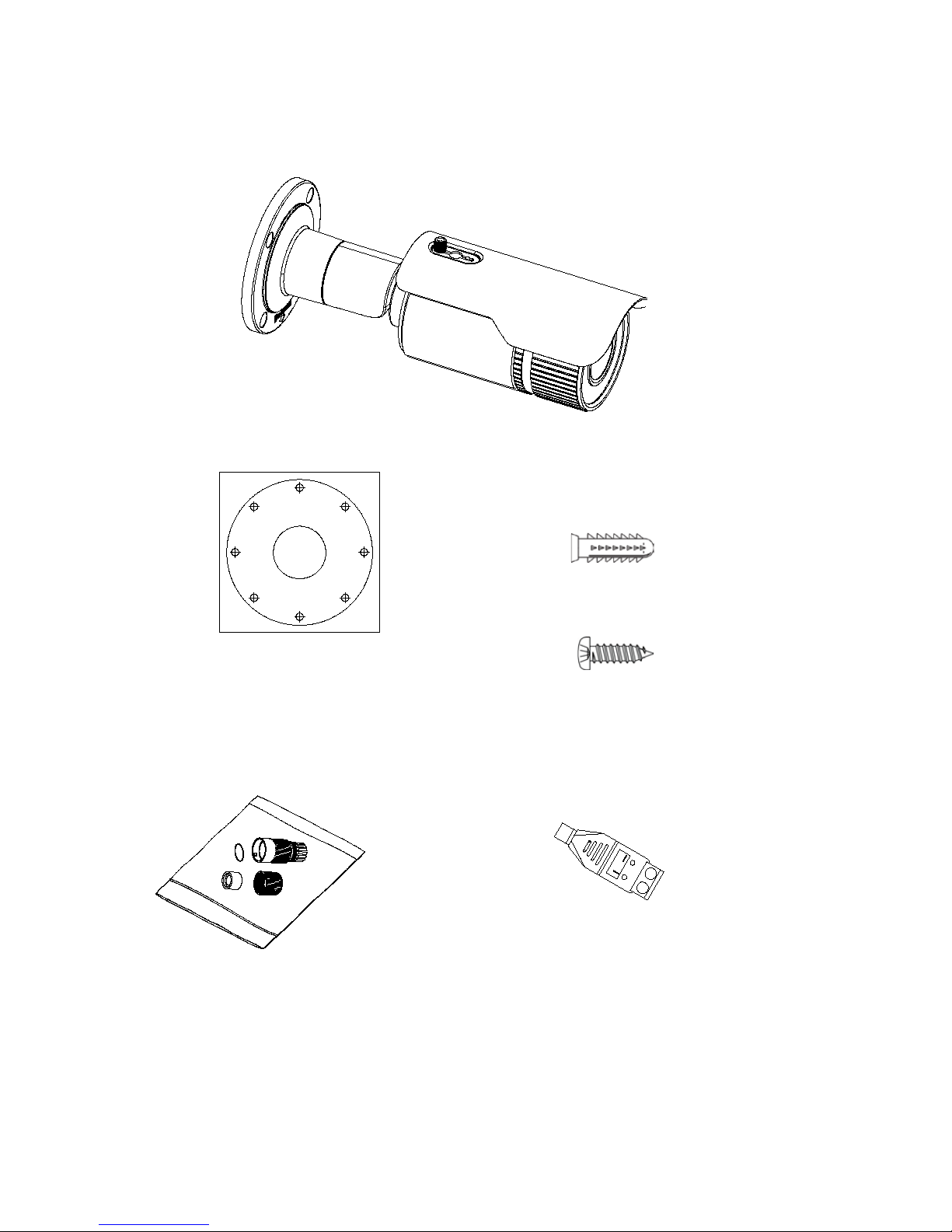
6 Installation Guide
IP VF lens bullet camera
Camera:
Drill template:
Screws:
Drywall anchor
7.5 × 24.5 mm (4 pcs)
Screw
M4 × 25 mm (4 pcs)
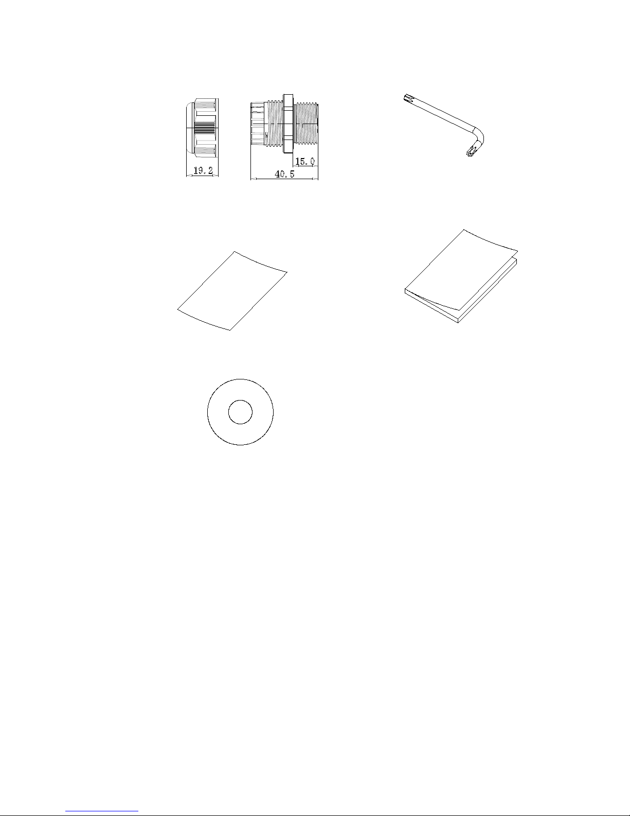
Water joint: Provides water
resistance to network cable
connector.
12 VDC connector:
Two terminal connector
with positive and
negative indicators.
Hole A: for cables routed through the wall
A
Drill Template
1
1
1
2
2
2
2
Screw hole 1: for integrative bracket
Screw hole 2: for conduit back box
Installation Guide 7
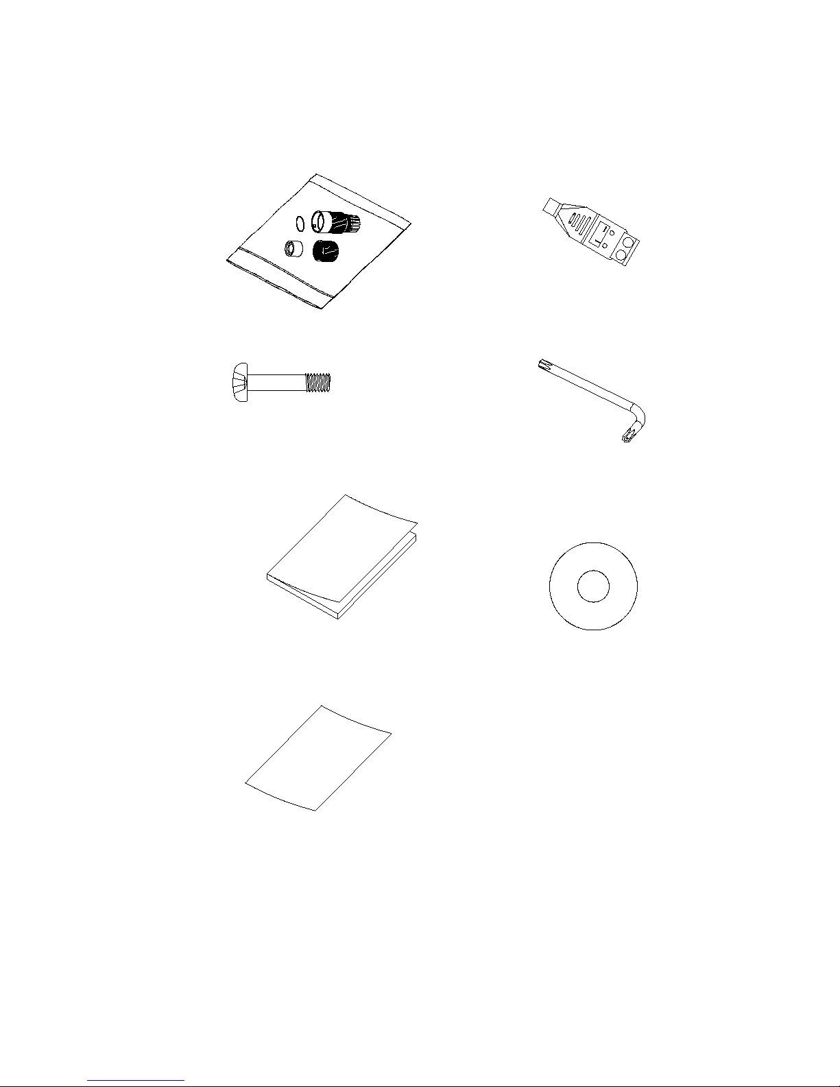
Video test cable:
Back box:
Screws: M4.8 × 8 (4 pcs)
Torx wrench:
Installation manual:
CD with manuals and
TruVision Device
Manager:
Equipment and Battery
Disposal sheets:
8 Installation Guide
IP motorized lens bullet camera
Camera:
Drill template:
Screws:
Drywall anchor
7.5 × 24.5 mm (4 pcs)
Screw
M4 × 25 mm (4 pcs)
Video test cable:
Back box:
Hole A: for cables routed through the wall
A
Drill Template
1
1
1
2
2
2
2
Screw hole 1: for integrative bracket
Screw hole 2: for conduit back box
Installation Guide 9
Water joint: Provides water
resistance to network cable
connector.
12 VDC connector:
Two terminal connector
with positive and
negative indicators.
Screws: M4.8 × 8 (4 pcs)
Torx wrench:
Installation manual:
CD with manuals and
TruVision Device
Manager:
Equipment and Battery
Disposal sheets:

10 Installation Guide
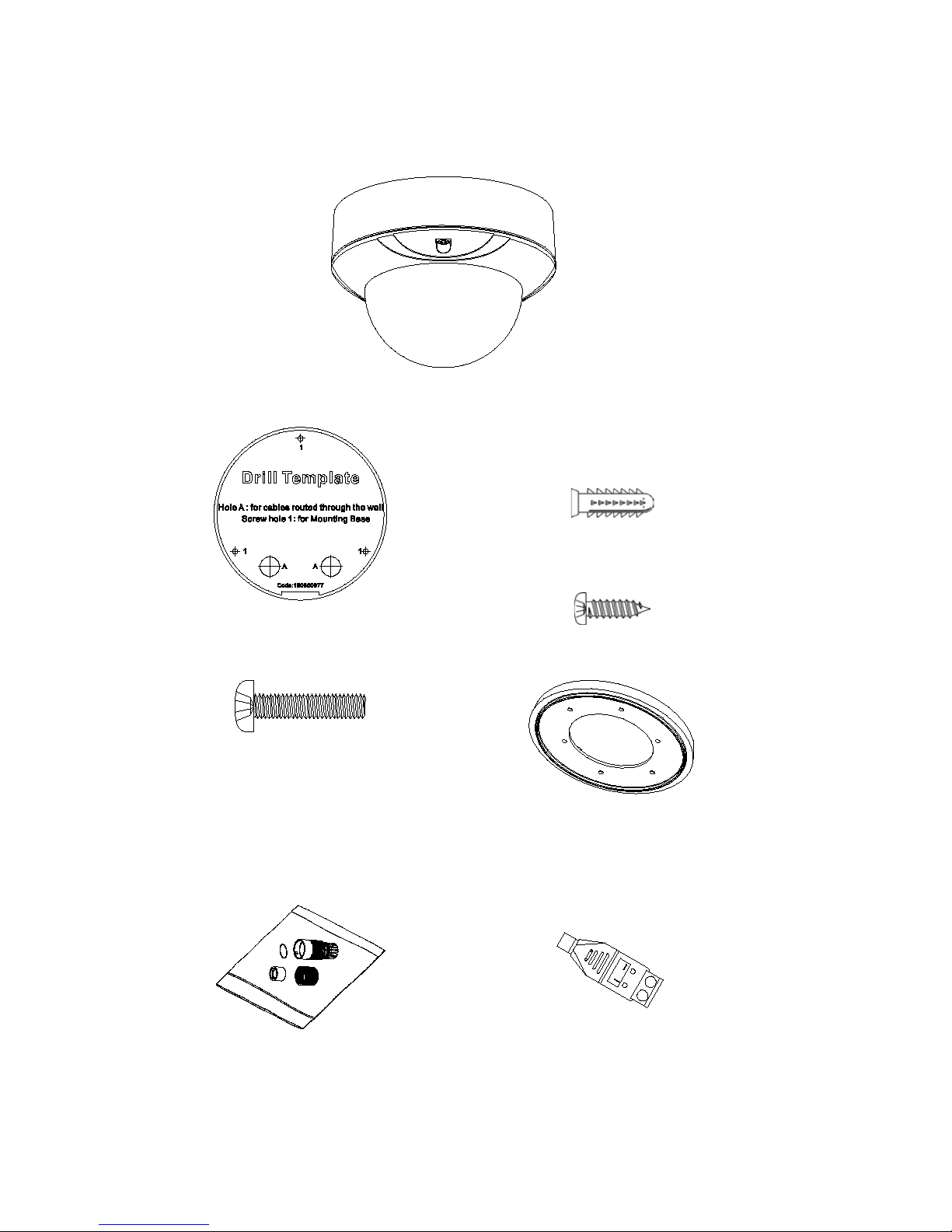
IP fixed lens dome camera
Camera:
Template:
Screws:
Drywall anchor
7.5 × 24.5 mm (3 pcs)
Screw
M4 × 25 mm (3 pcs)
Water joint: Provides water
resistance to network cable
connector.
12 VDC connector:
Two terminal connector
with positive and
negative indicators.
Drill Template
Hole A: for cables routed through the ceiling
screw hole 1: for Mounting Base
1
1
1
A
Installation Guide 11
Screws: 4 × 75 mm (3 pcs)
Torx wrench:
Installation manual:
CD with manuals and
TruVision Device
Manager:
Equipment and Battery
Disposal sheets:

12 Installation Guide
IP VF lens dome camera
Camera:
Drill template:
Screws:
Drywall anchor
7.5 × 24.5 mm (4 pcs)
Screw
M4 × 25 mm (4 pcs)
Screws: M4 × 9 (3 pcs)
Mounting adaptor plate:
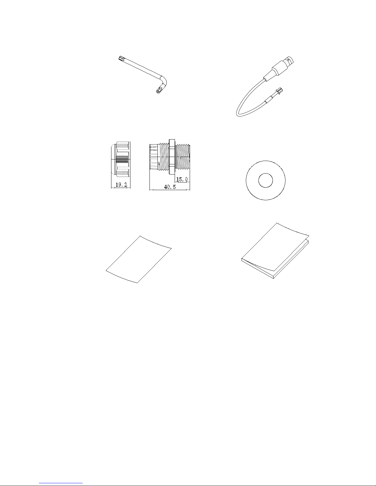
Water joint: Provides water
resistance to network cable
connector.
12 VDC connector:
Two terminal connector
with positive and
negative indicators.
Installation Guide 13
Plastic G3/4 cable adapter:
(mm)
Torx wrench:
Equipment and Battery
Disposal sheets:
Installation manual:
CD with manuals and
TruVision Device Manager:
14 Installation Guide
IP motorized lens dome camera
Camera:
Drill template:
Screws:
Drywall anchor
7.5 × 24.5 mm (4 pcs)
Screw
M4 × 25 mm (4 pcs)
Screws: M4 × 9 (3 pcs)
Mounting adaptor plate:
Water joint: Provides water
resistance to network cable
connector.
12 VDC connector:
Two terminal connector
with positive and
negative indicators.
Installation Guide 15
Torx wrench:
Video test cable:
Plastic G3/4 cable adapter:
(mm)
CD with manuals and
TruVision Device
Manager:
Equipment and Battery
Disposal sheets:
Installation manual:
 Loading...