

Page 1

TruVision IR
Bullet Camera
TVB
Installation Guide
P/N 1072925 • REV A • ISS 10FEB15
-2203 / TVB-4203
Page 2

Page 3

Content
Product overview 1
Camera description 3
Installation 4
Programming 8
Setup menu 9
Specifications 10
Regulatory information 11
Product overview
This is the TruVision Bullet IR Camera Installation
Guide for models TVB-2203/TVB-4203. This guide
describes a standard installation.
Installation Guide 1
Page 4
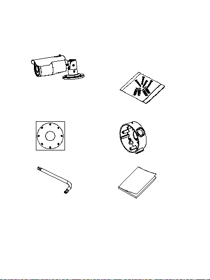
Package contents:
Ceiling Mounting
1
1
1
1
2
2
2
2
1:Screw Hole for
Bracket
2:Screw Hole for
Mounting Base
Camera with power
and video output
cables
Template
Hex wrench
2 Installation Guide
4 M4 screws (4 x
25 mm) and 4 dry wall
anchors (Ø7.5 x
24.5 mm) for wall or
ceiling installation
Back box
Installation Guide
Page 5
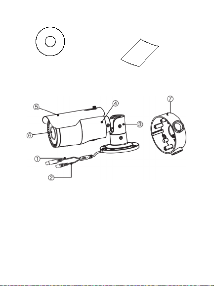
CD
7. Back box
• WEEE and Battery
Disposal
Camera description
1. Video cable
2. Power cable
3. Bracket
Installation Guide 3
4. Came ra
5. Sunshield
6. Lens
Page 6

Installation
Ceiling Mounting
1
1
1
1
2
2
2
2
1:Screw Hole for
Bracket
2:Screw Hole for
Mounting Base
To install the camera:
1. Using the template, place it level against the
mounting surface and mark the position of the
mounting holes.
2. Following all local codes, drill and prepare the
mounting holes.
3. Install the back box on the wall (optional).
4 Installation Guide
Page 7

4. Route the cables to the cable hole and connect
the corresponding cables. Connect a 75 ohm
coaxial video cable to the video cable, and
connect a 12 VDC power supply to the power
cable.
5. Secure the camera to the ceiling or wall with the
supplied screws.
Installation Guide 5
Page 8

6. Loosen the three camera screws and adjust the
camera according to the figure below to get an
optimum angle. Tighten the screws after
completing the adjustments.
6 Installation Guide
Page 9

7. Adjust the zoom screw and focus screw until you
OSD button
360°
90°
360°
get the optimum surveillance angle.
Focus
Zoom
8. Use the OSD button to configure the camera
parameters.
Installation Guide 7
Page 10

Programming
The camera can be programmed using OSD menus.
Once the camera hardware has been installed, you
configure the camera by using a TVS-C200 controller
(purchase separately).
The Setup menu provides access to the camera
configuration options. Please refer to the configuration
manual for further information on setting up the
camera. See page 9 for the setup menu.
Program the camera by attaching a standard video
monitor to the system.
To access the Setup menu:
1. Press the OSD control button (Enter) to access
the Main menu and its submenus.
2. Push the button up, down, left and right to move
between menu options.
3. Press the OSD control button to select an option.
4. When in a submenu, select Return to return to
the previous menu.
5. To exit the Main menu, move the cursor to Exit at
the bottom of the screen and press Enter. All
changes are saved.
8 Installation Guide
Page 11

Setup menu
Installation Guide 9
Page 12

Specifications
Power supply 12 VDC
Current Max. 420 mA
Power consumption Max. 5 W
Weight (net) 1350 g (1.97 lb.)
Dimensions 105 x 95 x 265.4 mm
10 Installation Guide
(4.13 x 3.74 x 10.43 in.)
Page 13

Regulatory information
Copyright:
may cause radio interference in which case the user may be requi red to
© 2015 United Technologies Corporation.
Interlogix is part of UTC Building & Industrial Systems, a unit of United
Technologies Corporation. All right s reserved.
Trademarks and patent s:
Trade names used in this document may be trademarks or registered
trademarks of the manufacturers or vendors of the respective products.
Manufacturer:
Interlogix
2955 Red Hill Avenue, Costa Mesa, CA 92626-5923, USA
Authorized EU manufacturing r epresentative:
UTC Fire & Security B.V.
Kelvinstraat 7, 6003 DH Weert, The Netherlands
Certification:
N4131
FCC compliance: Class A
Class A: This equipment has been tested and found to com ply with the
limits for a Class A digital device, pursuant to par t 15 of the FCC Rules.
These limits are designed to provide reasonable prot ection against harmful
interference when the equipment is operated i n a commercial environment.
This equipment generates, uses, and can radiat e radio frequency energy
and, if not installed and used in accordance with the i nstruction manual,
may cause harmful interference to radio communi cations. Operation of this
equipment in a residential area is likely to cause harmful interference in
which case the user will be required to correct the interferenc e at his own
expense.
ACMA compliance
Notice! This is a Class A product. In a domestic environment t his product
Installation Guide 11
Page 14

take adequate measures.
Canada
This Class A digital apparatus com plies with Canadian ICES-003.
Cet appareil numérique de la classe A est conform e à la norme NMB-0330
du Canada.
European Union directives:
12004/108/CE (EMC directive): Hereby, UT C Fire & Security declares that
this device is in compliance with the essential requirements and other
relevant provisions of Dir ective 2004/108/EC.
Contact information:
For contact information, see www.interl ogix.com or
www.utcfssecurityproducts.eu..
2012/19/EU (WEEE directive): Products marked with
this symbol cannot be disposed of as unsorted munici pal
waste in the European Union. For proper recycling, return
this product to your local supplier upon the pur chase of
equivalent new equipment, or dispose of it at designat ed
collection points. For more informati on see:
www.recyclethis.info.
12 Installation Guide
Page 15

Page 16

 Loading...