

Page 1

TT3010
TR3010
TT3010-R3
TT3020WDM
TT3020WDM-R3
TT3030
TT3030-R3
TT3030WDM
TT3030WDM-R3
TR3010-R3
TR3020WDM
TR3020WDM-R3
TR3030
TR3030-R3
TR3030WDM
TR3030WDM-R3
IFS Fiber Module
Installation & Operation
Instructions
P/N 1062835 • REV B • ISS 01AUG11
Page 2
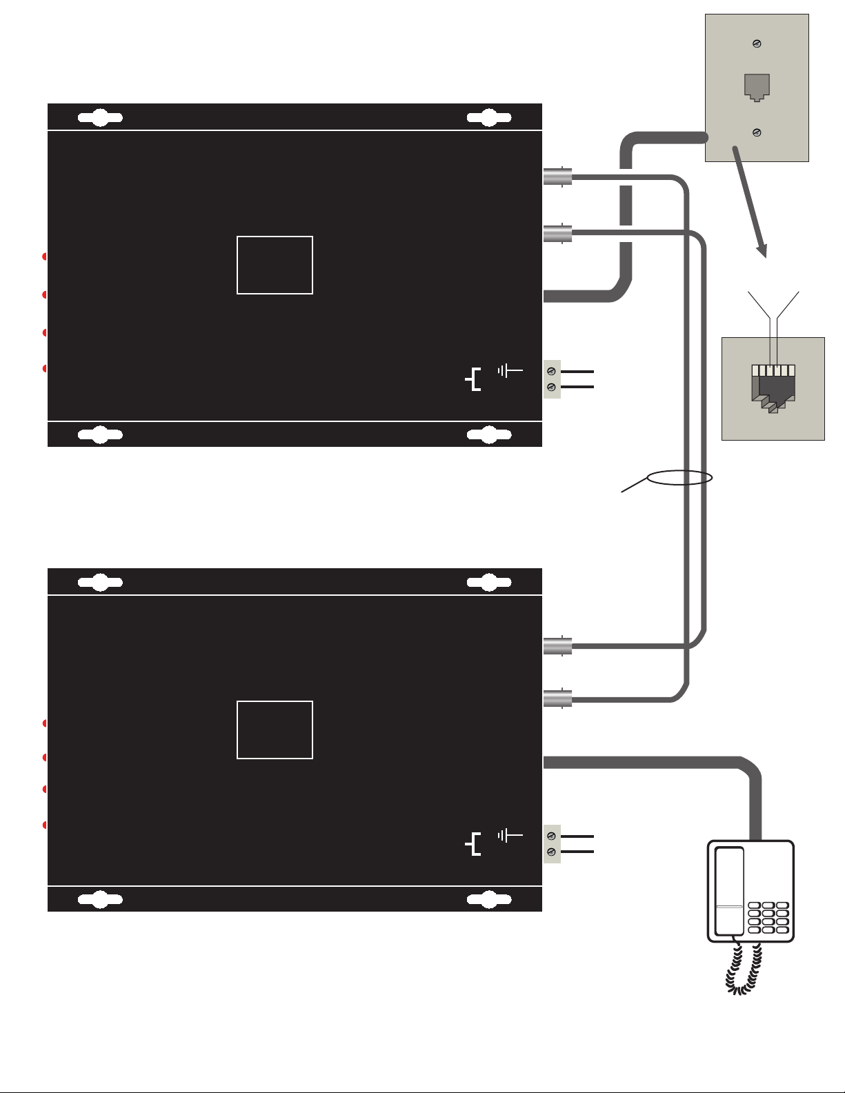
TT3010
DIGITAL POTS LINE END
OPTICAL OUT
LINK STATUS
OFF-HOOK
RING DETECT
POWER
International
Fiber
ifs
DIGITAL POTS TELEPHONE END
Systems
Incorporated
TR3010
OPTICAL IN
PHONE CONNECTION
POWER
+12 VDC- 1
Simplex multimode
fiber optic cable
- 2
Black wire
Black with
white stripe
Ring
Pin 4
Tip
Pin 3
16
LINK STATUS
OFF-HOOK
RING DETECT
POWER
ifs
International
Fiber
Systems
Incorporated
OPTICAL OUT
OPTICAL IN
PHONE CONNECTION
POWER
- 2
+12 VDC- 1
Black wire
Black with
white stripe
Note: To verify the number of fiber optic cables, and fiber optic cable types
of other models within this series, check the compatibility chart and part
number description sections within this manual.
Page 3
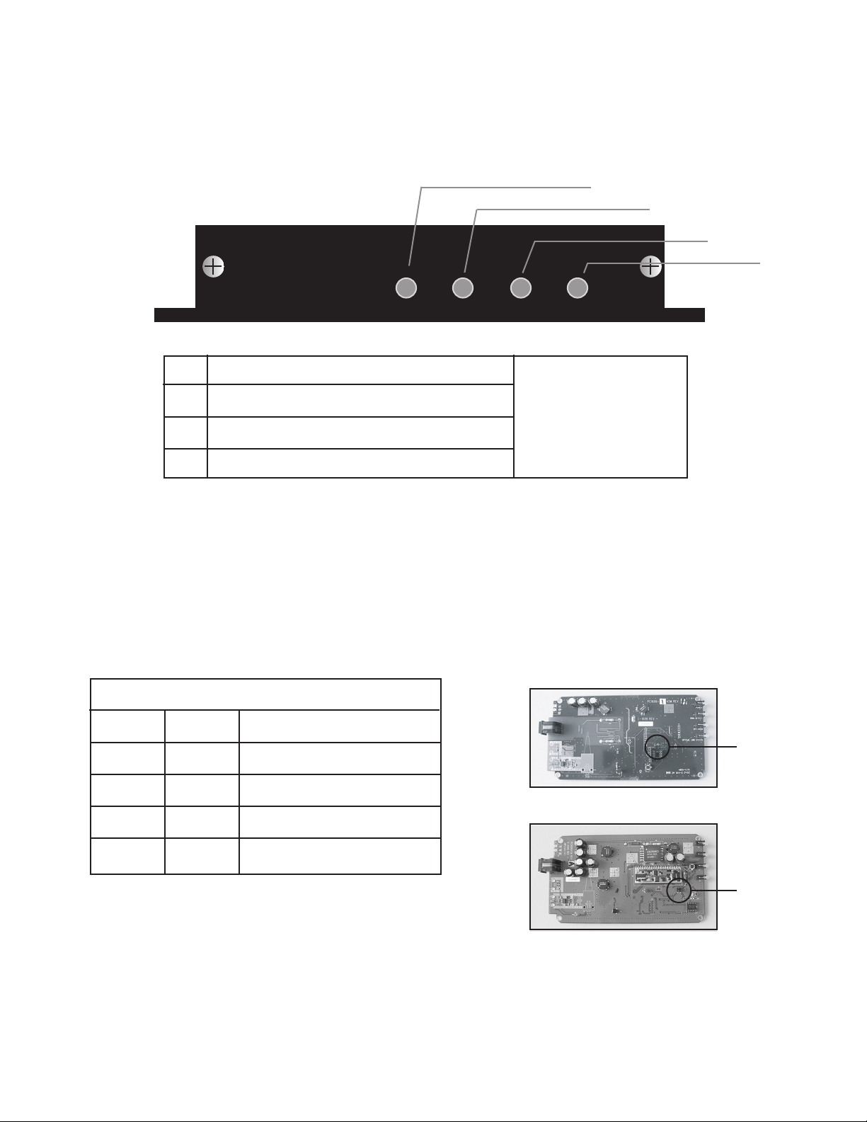
TT/TR3000
A
A
Link Status
B
Off-Hook
C
Ring Detect
D
Power
NOTE: All units set to USA/Canada standard.
LED illuminates
B
C
D
J6
ON
OFF
ON
OFF
WORLD STANDARD JUMPER SETTINGS
TT
JUMPER SETTING
J7
ON
ON
OFF
OFF
* UK includes the following countries:
Austria, Belgium, Denmark, Finland, France, Germany, Greece, Iceland,
Ireland, Italy, Luxembourg, Netherlands, Portugal, Spain, Sweden, Switzerland.
STANDARD
USA/CANADA
UK*
AUSTRALIA
JAPAN
TR
J7 J6
J6 J7
Page 4

FCC Compliance
This device complies with Part 15 of the FCC Rules. Operation is subject to the following two
conditions: (1) This device may not cause harmful interference, and (2) this device must accept
any interference received, including interference that may cause undesirable operation.
Changes or modifications not expressly approved by International Fiber Systems, Inc. could void
the user’s authority to operate the equipment.
NOTE: This equipment has been tested and found to comply with the limits for a Class A
digital device, pursuant to Part 15 of the FCC Rules. These limits are designed to provide
reasonable protection against harmful interference when the equipment is operated in a
commercial environment. This equipment generates, uses and can radiate radio frequency
energy and, if not installed and used in accordance with the instruction manual, may cause
harmful interference to radio communications. Operation of this equipment in a residential
area is likely to cause harmful interference in which case the user will be required to correct the
interference at his own expense.
CLASS 1 LASER PRODUCT
(For purposes of IEC 60825-1)
Complies with FDA Performance Standard for Laser Products
Title 21
Code of Federal Regulations
Subchapter J
Comprehensive
Lifetime Warranty
(a) Seller warrants to the original End User that products and any
services furnished hereunder will be free from defects in material
and workmanship as of the date of delivery, and will conform to
Seller’s published technical specications. The foregoing shall
apply only to failures to meet said warranties which appear within
that period of time during which the Products are installed in their
original installation for the original End User and operator of such
Products; provided, however, that in the event of product discontinuance, warranty support is limited to ve (5) years from the
announcement of discontinuance. Notwithstanding the preceding
sentence, the duration of the warranty period for
manufactured by Seller (e.g., ber optic cabling, test equipment,
power supplies or batteries) shall be the warranty period oered by
the original manufacturer, if any.
(b) The conditions of any tests shall be mutually agreed upon and
Seller shall be notied of, and may be represented at, all tests that
may be made. The warranties and remedies set forth herein are
conditioned upon (a) proper storage, installation, use and maintenance, and conformance with
Seller and (b) Buyer promptly notifying Seller of any defects and,
if required, promptly making the product available for correction.
(c) If any product or service fails to meet the foregoing warranties,
Seller shall thereupon correct any such failure either at its option,
any applicable recommendations of
products not
(i) by repairing any defective or damaged product or parts of the
products, or (ii) by making available any necessary repaired or
replacement products or parts thereof. Any repaired or replacement
part or product shall be warranted for the remaining period of the
original Warranty Period. Seller shall pay, or credit Buyer for, the
cost of freight for all return shipments of products or parts to
Buyer. Where a failure cannot be corrected by Seller's reasonable
eorts, the parties will negotiate an equitable adjustment in price.
(d) The preceding paragraph sets forth the exclusive remedies for
claims based on defect in or failure of products or services,
whether the claim is in contract, indemnity, warranty, tort
(including Seller's negligence), strict liability or otherwise and
however instituted. Upon the expiration of the warranty period,
liability shall terminate and BUYER shall have a reason-
all such
able time, within thirty days after the warranty period, to give
written notice of any defects which appeared during the warranty
period. The foregoing warranties are exclusive and in lieu of all
other warranties, whether written, oral, implied or statutory.
NO IMPLIED OR STATUTORY WARRANTY OF
MERCHANTABILITY OR FITNESS FOR PARTICULAR
PURPOSE SHALL APPLY. Seller does not warrant any
products or services of others which BUYER has designated.
Page 5

FCC Part 68 Registration
Customer Information
This equipment complies with Part 68 of the FCC rules and the requirements adopted by the
ACTA. On the bottom of this equipment is a label that contains, among other information, a
product identier in the format US: FIBOT01BTT3000. If requested, this number must be
provided to the telephone company.
This product uses USOC jacks: RJ11C
A plug and jack used to connect this equipment to the premises wiring and telephone network
must comply with the applicable FCC Part 68 rules and requirements adopted by the ACTA. A
compliant telephone cord and modular plug is provided with this product. It is designed to be
connected to a compatible modular jack that is also compliant.
The REN is used to determine the number of devices that may be connected to a telephone line.
Excessive RENs on a telephone line may result in the devices not ringing in response to an
incoming call. In most but not all areas, the sum of RENs should not exceed ve (5.0). To be
certain of the number of devices that may be connected to a line, as determined by the total
RENs
, contact the local telephone company. For products approved after July 23, 2001, the REN
for this product is part of the product identier that has the format US: FIBOT01BTT3000.
digits represented by ## are the REN without a decimal point (e.g., 03 is a REN of 0.3).
If this equipment, TT3000 or TR3000, causes harm to the telephone network, the telephone
company will notify you in advance that temporary discontinuance of service may be required.
But if advance notice is not practical, the telephone company will notify the customer as soon
as possible. Also, you will be advised of your right to le a complaint with the FCC if you
believe it is necessary.
The telephone company may make changes in its facilities, equipment, operations or procedures
that could aect the operation of the equipment. If this happens the telephone company will
provide advance notice in order for you to make necessary modications to maintain
uninterrupted service.
The
If trouble is experienced with this equipment TT3000 or TR3000, for repair or warranty information, please contact International Fiber Systems by calling 203-426-1180. If the equipment is
causing
harm to the telephone network, the telephone company may request that you disconnect
the equipment until the problem is resolved.
In the case of repairs to be done, repairs may only be performed by IFS trained personnel.
This equipment is not intended to be used on party lines. Connection to party line service is subject to state taris. Contact the state public utility commission, public service commission or
corporation commission for information.
If your home has specially wired alarm equipment connected to the telephone line, ensure the
installation of this TT3000 or TR3000 does not disable your alarm equipment. If you have
questions about what will disable alarm equipment, consult your telephone company or a
qualied installer.
Page 6

PROPER MOUNTING METHOD
FOR THE TT/TR3000
1) Locate unit on solid flat horizontal or vertical surface.
2) Position unit no closer than 24 inches from any power source or machinery.
3) Securely mount unit using (4) four mounting screws (not provided).
4) Select the correct voltage requirements for your application, +12VDC or 12VAC.
+12VDC attach black w/white stripe wire to pin 1 and black stripe to pin 2 (GND).
For 12VAC connect brown to pin 1, green to pin 2 and blue to pin 3 from adapter.
5) Plug power brick into approved 120v AC outlet.
6) Check power LED to insure device is properly powered, LED will illuminate green.
Page 7

Product Disassembly Instructions for WEEE
Per European Directive 2002/95/EC Waste Electrical
and Electronic Equipment
Required Tools:
One number 2 Phillips (crosstip) screwdriver.
One number 2 flat screwdriver.
For the enclosed box version:
1. Locate and remove box cover securement screws.
Usually, but not limited to at least 4 screws.
2. Lift off box top cover.
3. Locate and remove securement screws for printed circuit board.
4. If there are multiple boards to the assembly, continue removing
securement screws until none are left.
5. Lift off printed circuit board(s).
6. Disassembly of box version of product is complete.
For the rack version:
1. Locate and remove box cover securement screws
for printed circuit board. Usually, but not limited to at least 4 screws.
2. If there are multiple boards to the assembly, continue removing
securement screws until none are left.
3. Lift off printed circuit board(s).
4. Disassembly of box version of product
TT/TR3000 Environmental Specifications
MTBF: >100,000 hours
Operating Temp: -40˚C to +74˚C
Storage Temp: -40˚C to +85˚C
Relative Humidity: 0% to 95% (non-condensing)
†
May be extended to condensation conditions by adding suffix ‘-C’
to model number for conformal coating.
is complete.
†
Page 8

Contacting us
For help installing, operating, maintaining, and troubleshooting this product, refer to this document and any
other documentation provided. If you still have questions, contact us during business hours (Monday through
Friday, excluding holidays, between 5 a.m. and 5 p.m. Pacific Time).
Sales and support contact information
North
America
Toll-free: 855.286.8889 in the US, including Alaska and Hawaii;
Puerto Rico; Canada.
Outside the toll-free area: 503.885.5700.
E-mail: techsupport@interlogix.com
Europe
Australia
Select Contact Us at www.utcfssecurityproducts.eu
security.tech.support@interlogix.com.au
Note: Be ready at the equipment before calling.
Online
Another great resource for assistance with your Interlogix product is our online publication library. To access
the library, go to our website at the following location:
http://www.interlogix.com/transmission
1
1. Many Interlogix documents are provided as PDFs (portable document format). To read these documents, you will
need Adobe Reader, which can be downloaded free from Adobe’s website at www.adobe.com.
Page 9

Copyright © 2011 UTC Fire & Security. All rights reserved.
r
Trademarks and
patents
Manufacture
Certification
ACMA compliance Notice! This
Canada This Class A digital apparatus complies with Canadian ICES-003.
European Union
directives
Interlogix and IFS names and logos are trademarks of
UTC Fire & Security.
Other trade names used in this document may be trademarks or
registered trademarks of the manufacturers or vendors of the
respective products.
UTC Fire & Security Americas Corporation, Inc.
2955 Red Hill Avenue, Costa Mesa, CA 92626-5923, USA
Authorized EU manufacturing representative:
UTC Fire & Security B.V.
Kelvinstraat 7, 6003 DH Weert, The Netherlands
N4131
product may cause radio interference in which case the user may be
required to take adequate measures.
Cet appareil numérique de la classe A est conforme à la norme
NMB-003 du
2004/108/EC (EMC directive): Hereby, UTC Fire & Security
decla
res that this device is in compliance with the essential
requirements and other relevant provisions of Directive
2004/108/EC.
is a Class A product. In a domestic environment this
Canada.
2002/96/EC (WEEE directive): Products marked with this sy mbol
cannot be disposed of as unsorted municipal waste in the European
Union. For proper recycling, return this product to your local supplier
upon the purchase of equivalent new equipment, or dispose of it at
designated collection points. For more information see:
www.recyclethis.info.
Contact information For contact information, see www.interlogix.com.
 Loading...