

Interlogix TVP-5101, TVP-5103, TVP-5102, TruVision TVP-5104, TruVision TVP-5105 Configuration Manual
Page 1

TruVision IP Compact PTZ
Camera Configuration
Manual
P/N 1073407-EN • REV B • ISS 23MAY18
Page 2

Copyright
©
2018 United Technologies Corporation.
Interlogix is part of UTC
Climate, Controls & Security
, a unit of United
Technologies Corporation.
All rights reserved.
Trademarks and
patents
T
rade names used in this document may be trademarks or
registered trademarks of the manufacturers or vendors of the
respective products.
Manufacturer
Interlogix
2955 Red Hill Avenue, Costa Mesa, CA 92626
-5923, USA
Authorized EU manufacturing representative:
UTC Fire & Security B.V.
Kelvinstraat 7, 6003 DH Weert, The Netherlands
Contact information
and manuals / tools /
firmware
For contact
information and to download the latest manuals, tools,
and firmware, go to the web site of your region.
Americas: www.interlogix.com
EMEA: www.firesecurit ypro duc ts .c om
Manuals are available in several languages
Australia/New Zealand: www.utcfs.com.au
Page 3

TruVision IP Compact PTZ Camera Configuration Manual 1
Content
Introduction 3
Contact information and manuals /tools /firmware 4
Network connection 5
Checking your web browser security level 5
Activating the camera 6
Overview of the camera web browser 9
Camera configuration 11
Configuration menu ov erview 11
Local configuration 12
System time 13
Network settings 15
Recording parameters 19
ROI encoding of an image 22
PTZ parameters 23
Intelligent tracking 30
Prioritize PTZ 31
Overlay text 32
Video image 33
OSD 36
Image parameters swi tch 38
Motion detection alarms 39
Tamper-proof alarms 41
Alarm Input 41
Alarm Output 42
Exception alarms 43
Audio exception detect ion 44
Face detection 45
Intrusion detection 47
Line crossing detection 48
Region entrance detec ti on 50
Region exiting detection 51
RS-485 settings 52
Recording schedule 53
Format storage devi c es 55
NAS settings 56
Snapshot parameters 56
Camera management 58
User management 58
RTSP authentication 60
IP address filter 62
Defining the security service 62
Page 4

2 TruVision IP Compact PTZ Camera Configuration Manual
Restore default settings 63
Import/export a configuration file 64
Upgrade firmware 64
Reboot camera 64
System service 65
About 65
Camera operation 66
Logging on and off 66
Live view mode 66
Playing back recorded video 66
Snapshots 68
Searching event logs 69
Index 75
Page 5

TruVision IP Compact PTZ Camera Configuration Manual 3
Introduction
This is the configuration manual for the following TruVision IP PTZ camera models:
TVP-5101 (2.0 MPX, 4X, 20 m IR, H.265/H.264)
TVP-5102 (2.0 MPX, 20X, 150 m IR, H.265/H.264)
TVP-5103 (3.0 MPX, 20X, 50 m IR, H.265/H.264)
The installation guide and configuration manual are available on our web site.
Refer to the table below for information on which feature/functions are supported in
each model.
Table 1: Features and functions supported by the camera models
Feature TVP-5101 TVP-5102 TVP-5103
Cross Line Detection Yes Yes Yes
Intrusion Detection Yes Yes Yes
Face Detection No No Yes
Unattended Baggage Detection No No No
Object Removal Detection No No No
Audio Exception Detection Yes Yes Yes
Region Entrance Detection No No Yes
Region Exit Detection No No Yes
Scene Change Detection No No No
Defocus Detection No No No
People/object Counting No No No
Intelligent Tracking No No Yes
Page 6

4 TruVision IP Compact PTZ Camera Configuration Manual
Contact information and manuals /tools
/firmware
For contact information and to download the latest manuals, tools, and firmware, go to
the web site of your region.
Americas:
www.interlogix.com
EMEA: www.firesecurityproducts.com
Manuals are available in several languages.
Australia/New Zealand:
www.utcfs.com.au
Page 7
TruVision IP Compact PTZ Camera Configuration Manual 5
Network connection
This manual explains how to configure the camera over the network with a web
browser.
TruVision IP PTZ cameras can be configured and controlled using Microsoft Internet
Explorer (IE) and other browsers. The procedures described use Microsoft Internet
Explorer (IE) web browser.
Checking your web browser securit y level
When using the web browser interface, you can install ActiveX controls to connect and
view video using Internet Explorer. However, you cannot download data, such as video
and images due to the increased security measure. Consequently you should check the
security level of your PC so that you are able to interact with the cameras over the web
and, if necessary, modify the Active X settings.
Configuring IE ActiveX contr ols
You should confirm the ActiveX settings of your web browser.
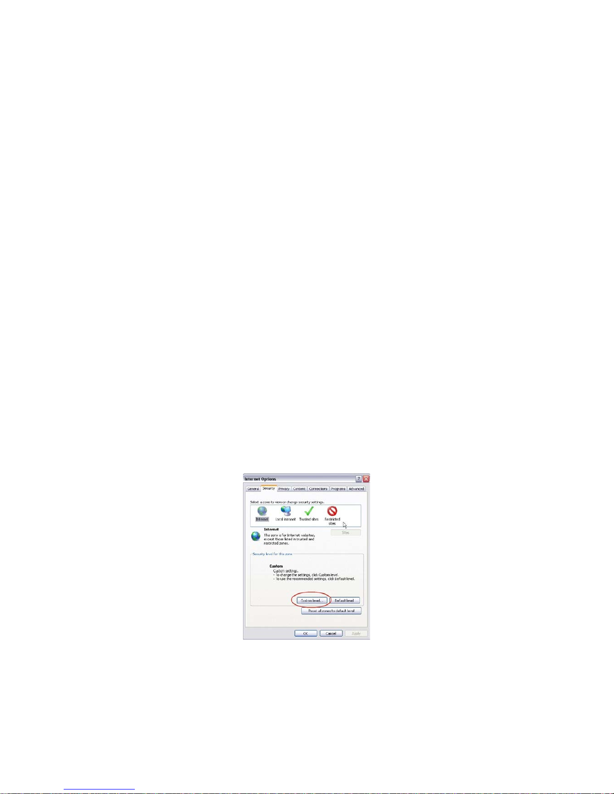
To change the web browser’s security level:
1. In Internet Explorer click Internet Options on the Tools menu.
2. On the Security tab, click the zone to which you want to assign a web site under
“Select a web content zone to specify its security settings”.
3. Click Custom Level.
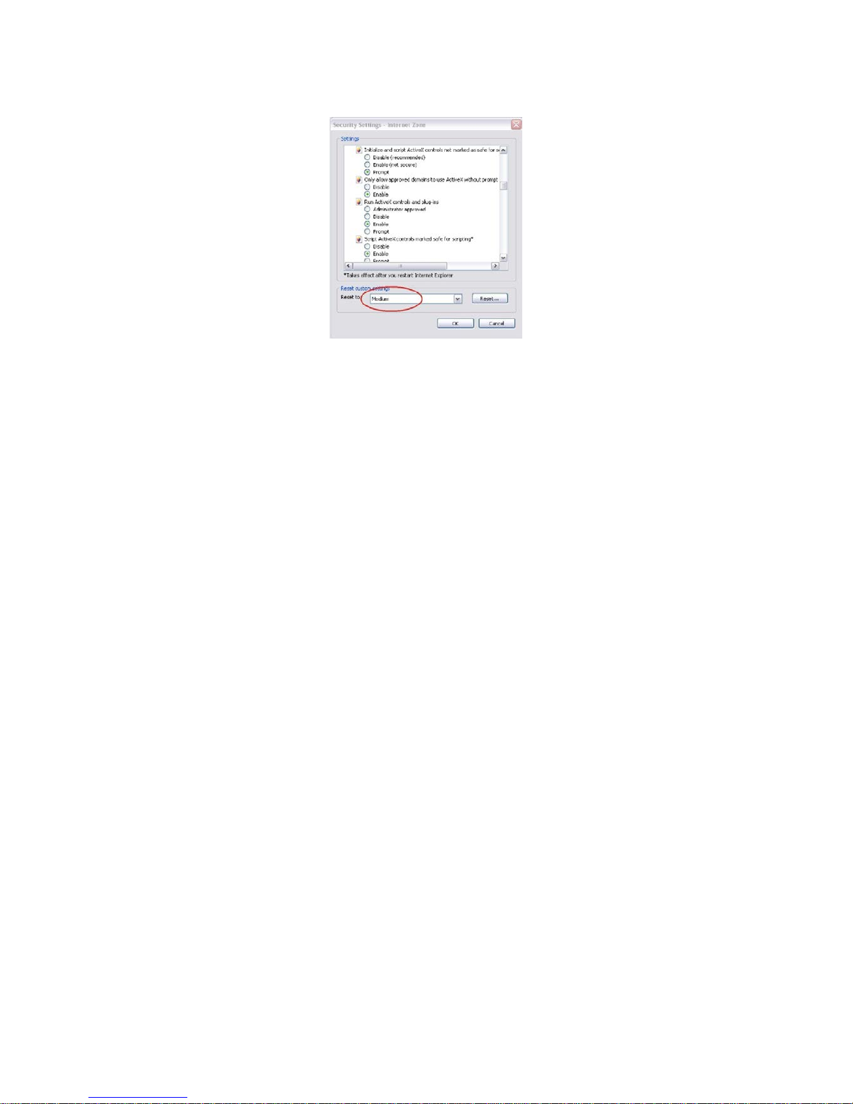
4. Change the ActiveX controls and plug-ins options that are signed or marked as
safe to Enable. Change the ActiveX controls and plug-ins options that are
unsigned to Prompt or Disable. Click OK.
- Or -
Page 8
6 TruVision IP Compact PTZ Camera Configuration Manual
Under Reset Custom Settings, click the security level for the whole zone in the
Reset To box, and select Medium. Click Reset.
Then click OK to the Internet Options Security tab window.
5. Click Apply in the Internet Options Security tab window.
Windows users
Internet Explorer for Windows operating systems have increased security measures to
protect your PC from any malicious software being installed.
To have complete functionality of the web browser interface with Windows, do the
following:
• Run the Browser interface as an administrator in your workstation
• Add the camera’s IP address to your browser’s list of trusted sites
To add the camera’s IP address to Internet Explorer’s list of trusted sites:
1. Open Internet Explorer.
2. Click Tools, and then Internet Options.
3. Click th e Security tab, and then select the Trusted sites icon.
4. Click th e Sites button.
5. Clear the “Require server verification (https:) for all sites in this zone box.
6. Enter the IP address in the “Add this website to the zone” field.
7. Click Add, and then click Close.
8. Click OK in the Internet Options dialog window.
9. Connect to the camera for full browser functionality.
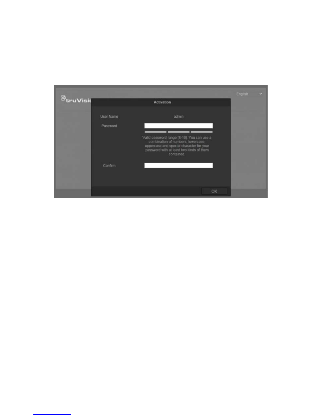
Activating the camera
When you fi r st start up the camera, the Activation window appears. You must define a
high-security admin password before you can access the camera. There is no default
password provided.
Page 9
TruVision IP Compact PTZ Camera Configuration Manual 7
You can activate a password via a web browser and via TruVision Device Manager
(included on the CD to find the IP address of the camera).
Activation via the web browser:
1. Power on the camera and connect the camera to the network.
2. Input the IP address in the address bar of the web browser, and click Enter to enter
the activation interface
Note:
The default IP address of the camera is 192.168.1.70.
For the camera to enable DHCP by default, you must activate the camera via
TruVision Device Manager. Please refer to the following section, “Activatio n via
TruVision Device Manager”.
3. Enter the password in the password field.
Note: A valid password range must be between 8 and 16 characters. You can use a
combination of numbers, lower and upper case letters, and special character s : _
- , . * & @ / $ ? Space. The password must contain characters from at least two of
these groups. We also recommend that you reset your password regularly. For high
security systems, it is particularly recommended to reset the password monthly or
weekly for better protection.
4. Confirm the password
5. Click OK to save the password and enter the live view interface.
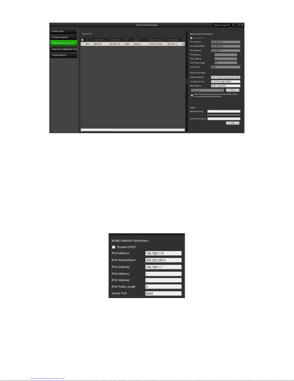
Activation via the web browser:
1. Run the TruVision Device Manager to search for online devices.
2. Check the device status from the device list, and select the inactive device.
Page 10
8 TruVision IP Compact PTZ Camera Configuration Manual
3. Enter the password in the password field, and confirm it.
Note: A valid password range must be between 8 and 16 characters. You can use a
combination of numbers, lower and upper case letters, and special characters : _
- , . * & @ / $ ? Space. The password must contain characters from at least two of
these groups. We also recommend that you reset your password regularly. For high
security systems, it is particularly recommended to reset the password monthly or
weekly for better protection.
4. Click OK to save the password.
A pop-up window appears to confirm activation. If activation fails, confirm that the
password meets the requirements and try again.
5. Change the device IP address to the same subnet with your computer by either
modifying the IP address manually or checking the check box of Enable DHCP.
6. Input the password and click the Save button to activate your IP address
modification.
Page 11
TruVision IP Compact PTZ Camera Configuration Manual 9
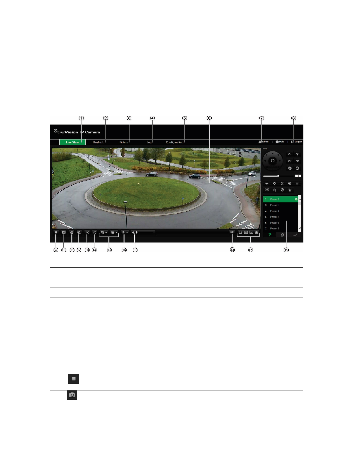
Overview of the camera web browser
The camera web browser lets you view, record, and play back recorded videos on the
optional SD card as well as manage the camera from any PC with Internet access. The
browser’s easy-to-use controls give you quick access to all camera functions. See
Figure 1 below.
If there is more than one camera connected over the network, open a separate web
browser window for each individual camera.
Figure 1: Web browser interface
Name
Description
1. Live view Click to view live video.
2. Playback Click to play back video.
3. Picture Click to search for evet pictures and continues pictures
4. Log Click to search for event logs. There are three main types:
Alarm, Exception, and Operation.
5. Configuration Click to display the configuration window for setting up the
camera.
6. Viewer View live video. Time, date and camera name are displayed
here.
7. Current user Displays current user logged on.
8. Logout Click to log out from the system. This can be done at any
time.
9.
Start/stop live
view
Click to start/stop live view.
10.
Capture Click to take a snapshot of the video. The snapshot will be
saved to the default folder in JPEG (or BMP) format. The
directory of the folder can be set in Local Configuration
>Browser Configuration.
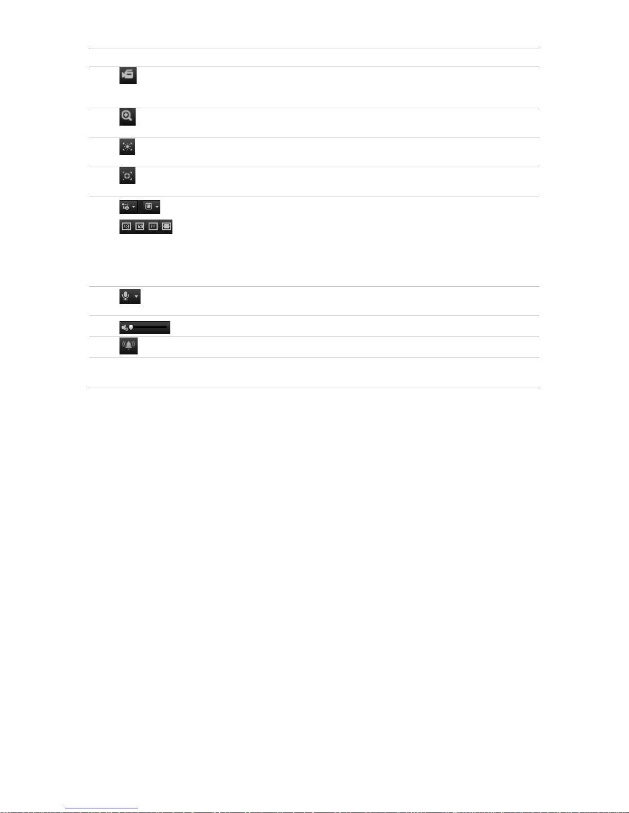
Page 12
10 TruVision IP Compact PTZ Camera Configuration Manual
Name
Description
11.
Start/stop
recording
Click to record live video. The video will be saved to the
default folder and the directory of the folder can be set in
Local Configuration > Browser Configuration.
12.
3D Zoom Click to enable 3D zoom and draw a rectangle using the left
mouse button to specify where you want to zoom in.
13.
Enable Regional
Exposure
Click to enable regional exposure
14.
Enable Regional
Focus
Click to enable regional focus
15.
Display Control Click each tab to adjust the layout and the stream type of the
live view. You can also click the drop-down menu to select the
plug-in (WebComponents or QuickTime).
For IE (internet Explorer) users, web components and Quick
Time are selectable. For non-IE users, web components,
QuickTime, VLC, or MJPEG are selectable if they are
supported by the web browser.
16.
Bidirectional
audio
Turn on/off the microphone (optional).
17.
Audio Drag to adjust the volume.
18.
Manual Alarm Click to trigger manual alarm
19.
PTZ control
panel
Use this control panel to control pan/tilt/zoom and to carry out
other camera functions, such as selecting presets.
Page 13
TruVision IP Compact PTZ Camera Configuration Manual 11
Camera configuration
This chapter explains how to configure the cameras through a web browser.
Once the camera hardware has been installed, configure the camera’s settings through
the web browser. You must have administrator rights in order to configure the cameras
over the internet.
The camera web browser lets you configure the camera remotely using your PC. Web
browser options may vary depending on camera model. The camera is configured
using the browser.
There are two main folders in the configuration panel:
Local configuration
Configuration
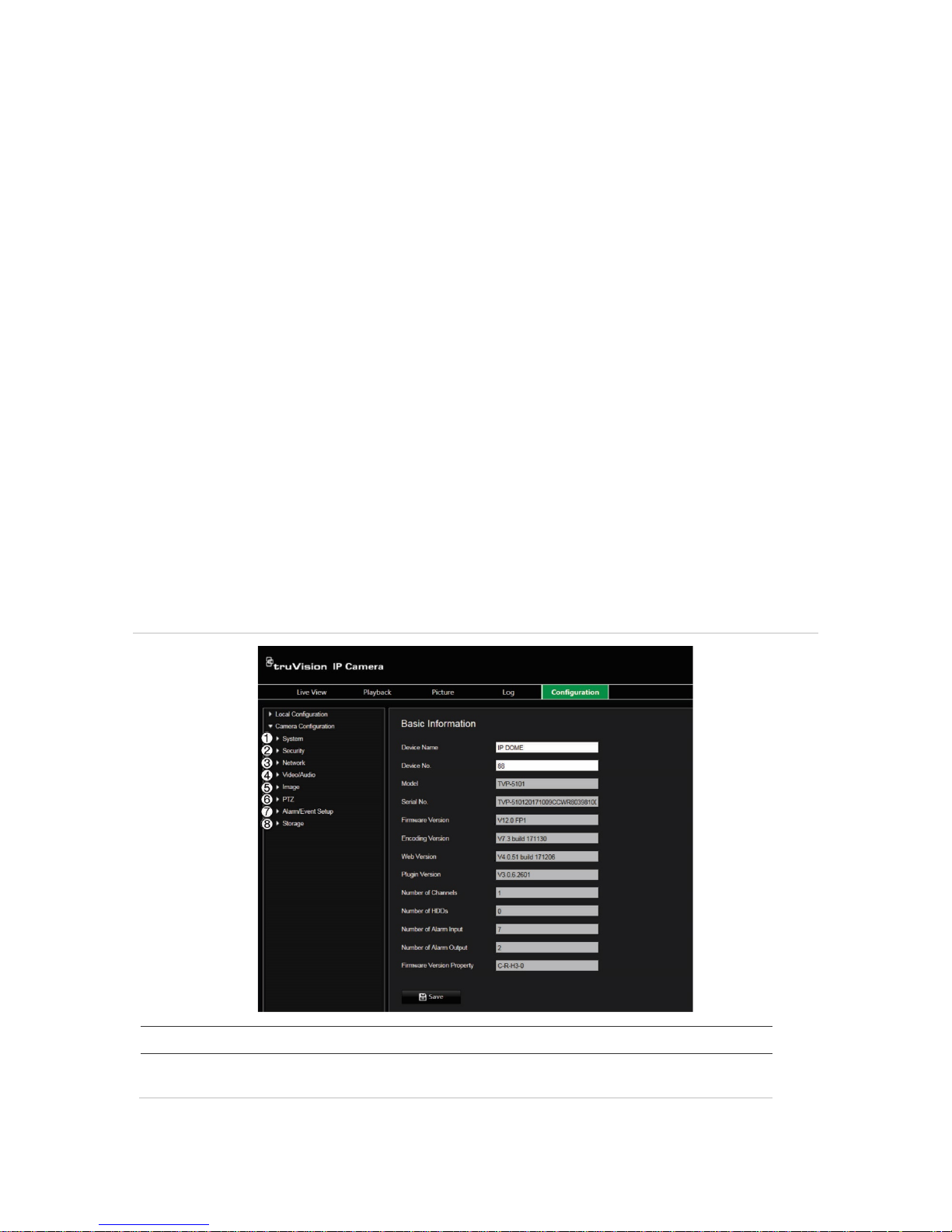
Configuration menu overview
Use the Configuration panel to configure the system, network, camera, alarms, users,
transactions, and other parameters such as upgrading the firmware. See Figure 2
below for descriptions of the configuration folders available.
Figure 2: Configuration window (Device Information tab of the System folder selected)
Item Description
1.
System
Defines device basic information including SN and the current firmware
version, time settings, and maintenance parameters.
Page 14
12 TruVision IP Compact PTZ Camera Configuration Manual
Item Description
2.
Security
Defines who can use the camera, their passwords and access privileges,
RTSP authentication, IP address filter, and telnet access.
3.
Network
Defines the network parameters required to access the camera over the
internet.
4.
Video/Audio
Defines recording parameters.
5.
Image
Defines the image parameters, OSD settings and text overlay.
6.
PTZ
Defines the PTZ parameters and privacy masking.
7.
Alarm/
Event
Setup
Defines motion detection, tamper-proof, alarm input/output, exception,
and audio exception detecti on.
8.
Storage
Defines recording schedule, storage management, NAS configuration
and snapshot configuration.
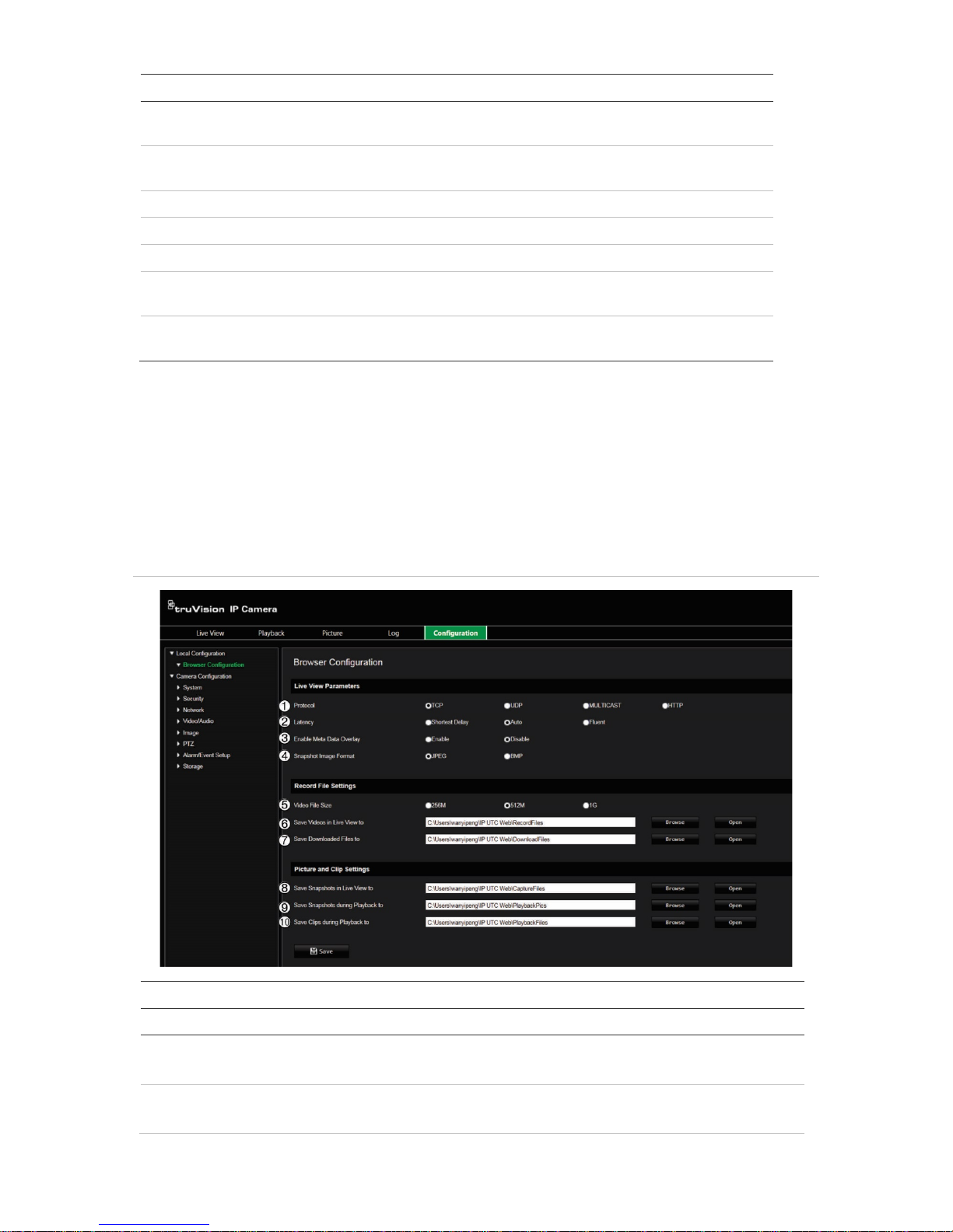
Local configuration
Use the Local menu to manage the protocol type, live view performance, and local
storage paths. In the Configuration panel, click Local Configuration to display the local
configuration window. See Figure 3 below for descriptions of the different menu
parameters.
Figure 3: Example of a configuration window
Parameters
Description
Live View Parameters
1.
Protocol
Specifies the network protocol used.
Options include: TCP, UDP, MULTICAST and HTTP.
2.
Latency
Specifies the transmission speed.
Options include: Shortest Delay, Balanced or Fluent.
Page 15

TruVision IP Compact PTZ Camera Configuration Manual 13
Parameters
Description
3.
Enable Meta Data Overlay
It refers to the rules on your local browser. Specify whether or not
to display the colored marks when motion detection is triggered.
For example, when the rules option is enabled and motion is
detected, the moving object will be marked with a green rectangle
in live view.
4.
Snapshot I
mage Format Choose the image format for a snapshot: JPEG or BMP.
Record File Settings
5.
Video
File Size Specifies the maximum file size.
Options include: 256 MB, 512 MB and 1G.
6.
Save
Videos in Live View to Specifies the directory for recorded files.
7.
Save
Downloaded Files to Specifies the directory for downloaded files.
Picture
and Clip Settings
8.
Save
Snapshots in Live
View t
o
Specifies the directory for saving snapshots in live view mode.
9.
Save
Snapshots during
Playback t
o
Specifies the directory for saving snapshots in playback mode.
10.
Save Clips
during Playback
t
o
Specifies the directory for saving video clips in playback mode.
System time
NTP (Network Time Protocol) is a protocol for synchronizing the clocks of network
devices, such as IP cameras and computers. Connecting network devices to a
dedicated NTP time server ensures that they are all synchronized.
To define the system time and date:
1. From the menu toolbar, click Configuration > System > Time Settings.
Page 16
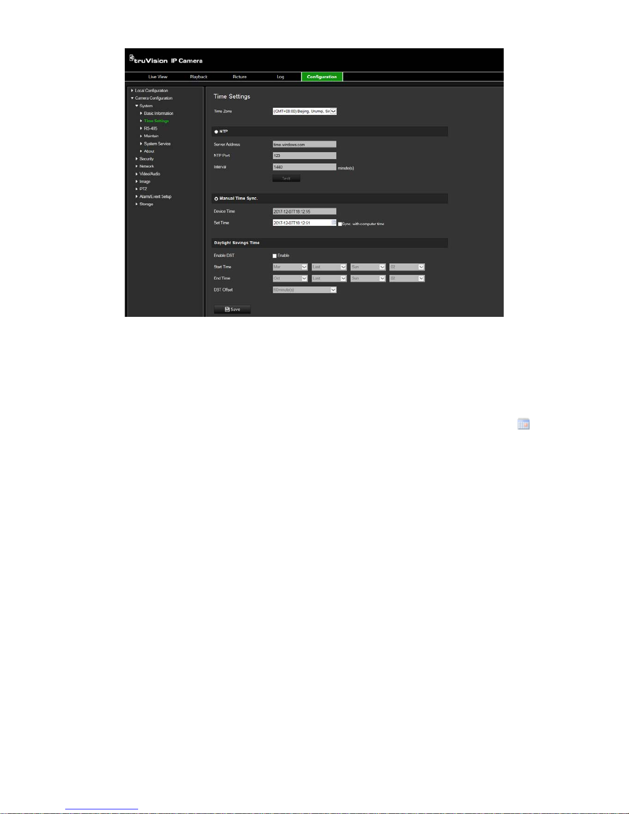
14 TruVision IP Compact PTZ Camera Configuration Manual
2. From the Time Zone drop-down menu, select the time zone that is the closest to the
camera’s location.
3. NTP: Enable the NTP function and enter the server NTP address to synchronize
with an NTP server. The time interval can be set from 1 to 10080 minutes.
-OrManual Time Sync.: Enable the Manual Time Sync function, and then click
to set the system time from the pop-up calendar.
Note: You can also check the Sync with computer time check box to synchronize
the time of the camera with the time of your computer.
4. Select Enable DST to enable the DST function, and set the date of the DST period.
5. Click Save to save changes.
Page 17

TruVision IP Compact PTZ Camera Configuration Manual 15
Network settings
Accessing the camera through a network requires that you define certain network
settings. Use the “Network” folder to define the network settings. See Figure 4 below for
further information.
Figure 4: Network window (TCP/IP tab shown)
Parameters
Description
1.
TCP/IP
NIC Type: Specifies the NIC type. Default is Auto. Other options include: 10M
Half-dup, 10M Full-dup, 100M Half-dup and 100M Full-dup.
DHCP: Enable to automatically obtain an IP address and other network
settings from that server.
IPv4 Address: Specifies the IPv4 address of the camera.
IPv4 Subnet Mask: Specifies the IPv4 subnet mask.
IPv4 Default Gateway: Specifies the IPv4 gateway IP address.
IPv6 Mode: Specifies the IPv6 mode, including Manual, DHCP and Router
Advertisement.
IPv6 Address: Specifies the IPv6 address of the camera.
IPv6 Subnet Mask: Specifies the IPv6 subnet mask.
IPv6 Default Gateway: Specifies the IPv6 gateway IP address.
Mac Address: Specifies the MAC address of the camera.
MTU: Specifies the valid value range of MTU. Default is 1500.
Multicast Address: Specifies a D-class IP address between 224.0.0.0 to
239.255.255.255. Only specify this option if you are using the multicast
function. Some routers prohibit the use of multicast function in case of a
network storm.
Page 18

16 TruVision IP Compact PTZ Camera Configuration Manual
Parameters
Description
DNS Server: Specifies the DNS server for your network and the alternate DNS
server that can be used.
Host Name Configuration: Specifies the DNS name the user can define.
2.
DDNS
Specifies IP server, DynDNS and ezDDNS.
3.
PPPoE
Use this option when using a direct modem connection between the camera
and ISP.
4.
Port
HTTP Port: Specifies the port used for the Internet Explorer (IE) browser.
Default value is 80.
RTSP Port: Specifies the RTSP port. The default port number is 554.
HTTPS Port:
Specifies the HTTPS port. The default port number is 443.
Server Port: Specifies the SDK port. T he default port number is 8000.
5.
NAT
A NAT (Network Address Translation) is used for network connection. Select
the port mapping mode: auto or manual.
6.
SNMP
Enable SNMP to report the camera status and parameters to SNMP software.
7.
FTP
Specifies the FTP address and folder to which snapshots of the camera
can be
uploaded.
8.
Email
Specifies the email address to which messages are sent when an alarm
occurs.
9.
HTTPS
Specifies authentication of the website and its ass oc iat ed web serv er, wh ich
protects against Man-in-the-middle attacks .
10.
QoS
Enable to solve the network delay and network congestion by configuring the
priority of data sending.
11.
802.1.X
When the feature is enabled, the camera data is secured and user
authentication is needed when connecting the camera to the network.
12.
Integration
protocol
If you need to access to the camera through the third party platform, you can
enable STD-CGI function. And if you need to access to the device through
ONVIF protocol, you can configure ONVIF user in this interface. Refer to
ONVIF standard for detailed configuration rules.
To define the TCP/IP parameters:
1. From the menu toolbar, click Camera Configuration > Network > TCP/IP.
2. Configure the NIC settings, including the NIC Type, IPv4 settings, IPv6 settings,
MTU settings, and Multicast Address.
3. If the DHCP server is available, check DHCP.
4. If the DNS server settings are required for some applications (e.g., sending email),
you should configure the Preferred DNS Server or Alternate DNS Server.
5. Click Save to save changes.
To define the port parameters:
1. In Camera Configuration > Network > Port.
2. Set the HTTP port, RTSP port, HTTPS port and Server port of the camera.
3. Click Save to save changes.
Page 19

TruVision IP Compact PTZ Camera Configuration Manual 17
To define the DDNS parameters:
1. From the menu toolbar, click Camera Configuration > Network > DDNS.
2. Check Enable DDNS to enable this feature.
3. Select DDNS Type. Two options are available: DynDNS and IPServer.
• DynDNS: Enter the following information:
- Domain name: DynDNS web site
- Server address: memb er s. dy ndns .or g
- Host name: URL created in DynDNS
- User name/password: login credentials for the DynDNS web site
- Port: 443 (because the connection to members.dyndns.org is a HTTPS
connection)
• ezDDNS: Enter the host name. It will automatically register it online.
You can define a host name for the camera. Make sure you entered a valid DNS
server in the network settings and have the necessary ports forwarded in the
router (HTTP, Server port, RSTP port).
• IPServer: Enter the address of the IP Server.
4. Click Save to save changes.
To define the PPPoE parameters:
1. From the menu toolbar, click Camera Configuration > Network > PPPoE.
2. Check Enable PPPoE to enable this feature. The dynamic IP address is assigned
automatically from the modem.
3. Enter User Name, Password, and Confirm password for PPPoE access.
4. Click Save to save changes.
To define the SNMP parameters:
Note: Before setting the SNMP, please download the SNMP software and manage to
receive the camera information via SNMP port. By setting the Trap Address, the
camera can send the al ar m event and ex cept ion messages to the surveillance center.
The SNMP version you select should be the same as that of the SNMP software.
1. From the menu toolbar, click Camera Configuration > Network > SNMP.
2. Select the corresponding version of SNMP: v1, v2c or v3.
Note: Contact your network administrator for specific information on setting up this
function.
3. Configure the SNMP settings. The configuration of the SNMP software should be
the same as the settings you configure here.
4. Click Save to save changes.
Page 20

18 TruVision IP Compact PTZ Camera Configuration Manual
To define the 802.1x parameters:
Note: The switch or router to which the camera is connected must also support the
IEEE 802.1X standard, and a server must be configured. Please apply and register a
user name and password for 802.1X in the server.
1. From the menu toolbar, click Camera Configuration > Network > 802.1X.
2. Check Enable IEEE 802.1X to enable the feature.
Note: Contact your network administrator for specific information on setting up this
function.
3. Configure the 802.1X settings, including EAPOL version, user name, and password.
The EAPOL version must be identical with that of the router or the switch.
4. Click Save to save changes.
To define the QoS parameters:
1. From the menu toolbar, click Camera Configuration > Network > QoS.
2. Configure the QoS settings, including Video / Audio DSCP, Event / Alarm DSCP
and Management DSCP. The valid value range of the DSCP is 0 to 63. The bigger
the DSCP value is the higher the priority is.
3. Click Save to save changes.
To define the FTP parameters:
1. From the menu toolbar, click Camera Configuration > Network > FTP.
2. Configure the FTP settings, including server address, port, user name, password,
directory structure, main directory, subdirectory, and upload type.
Directory: In the Directory Structure field, you can select the root directory, main
directory and tab. When the main directory is selected, you have the option to use
the Device Name, Device Number or Devi ce IP for the na me o f the di r ector y. When
the tab is selected, you can use the Camera Name, Camera No., or Custom as the
name of the directory.
Upload type: To enable uploading the snapshots to the FTP server.
3. Click Save to save changes.
To define the UPnP parameters:
1. Click Camera Configuration > Network > UPnP.
4. Check the checkbox to enable the UPnP functi on. Edit the friendly name of the
device when detected onli ne can be edi te d.
4. Click Save to save changes.
To set up the Email parameters:
1. In Camera Configuration > Network > Email.
2. Configure the following settings:
Sender: The name of the email sender.
Page 21

TruVision IP Compact PTZ Camera Configuration Manual 19
Sender’s Address: The email address of the sender.
SMTP Server: The SMTP Server IP address or host name.
SMTP Port: The SMTP port. The default is 25.
Enable SSL: Check the checkbox to enable SSL if it is required by the SMTP
server.
Attached Snapshot: Check the checkbox of Attached Snapshot if you want to
send emails with attached alar m snapshots.
Interval: This is the time between two actions of sending attached images.
Authentication: If your email server requires authentication, check this checkbox to
use authentication to log in to this server. Enter the login user name and password.
Receiver: The name of the user to be notified.
Receiver’s Address: The email address of user to be notified.
3. Click Save to save changes.
To set up the NAT parameters:
1. Click Camera Configuration > Network > NAT.
2. Check the checkbox to enable the NAT function.
3. Select Port Mapping Mode to be Auto or Manual. When you choose Manual mode,
you can set the external port as you want.
4. Click Save to save changes.
To set up the Integration protocol parameters:
1. Click Camera Configuration > Network > Integration Protocol.
2. Check the Enable STD-CGI checkbox and then select the authentication from the
dropdown list. Then you can access to the camera through the third party platform.
3. Check the Enable ONVIF checkbox to enable the function.
4. Click Add to add a new ONVIF user. Set the user name and password, and confirm
the password. You can set the user as media user, operator, and administrator.
5. Click Modify to modify the information of the added ONVIF user.
6. Click Delete to delete the selected ONVIF user.
7. Click Save to save changes.
Recording parameters
You can adjust the video and audio recording parameters to obtain the picture quality
and file size best suited to your needs. Figure 5 below list the video and audio recording
options you can configure for the camera.
Page 22

20 TruVision IP Compact PTZ Camera Configuration Manual
Note: When you add the camera to a recorder, you need to set-up the rec or di ng
parameters in the recorder.
Figure 5: Video & Audio Settings menu (Video tab shown)
Parameter Description
1. Stream Type Specifies the streaming method used.
Options include: Main Stream (Normal), Substream, and Third Stream.
Use main stream for live viewing and recording with high resolutions and
bandwidth. Use substream when there is a bandwidth limitation, such as
when using a mobile app. The third stream can be used for local live
viewing or as a backup to the other streams.
2. Stream Content Specifies the stream type you wish to record.
Select Video Stream to record video stream only. Select Video&Audio to
record both video and audio streams.
Note: Video&Audio is only available for those camera models that
support
audio.
3. Resolution Specifies the recording resolution. A higher image resolution provides a
higher image quality but also requires a higher bit rate. The resolution
options listed depend on the type of camera and on whether main or sub
stream is being used.
Note: Resolutions can vary depending on the camera model.
4. Bitrate Control Specifies whether variable or fixed bit rate is used. Variable produces
higher quality results suitable for video downloads and streaming. Default
is Constant.
5. Video Quality Specifies the quality level of the image.
It can be set when variable bit rate
is selected. Options include: Lowest, Lower, Medium, Higher, and
Highest.
Page 23
TruVision IP Compact PTZ Camera Configuration Manual 21
Parameter Description
6. Frame Rate Specifies the frame rate for the selected resolution.
The frame rate is the number of video frames that are shown or sent per
second.
Note: The maximum frame rate depends on the camera model and
selected resolution. Please check the camera specifications in its
datasheet.
7. Bitrate Target Specifies the maximum allowed bit rate. A high image resolution requires
that a high bit rate must also be selected.
Options include: 1024, 2048, 3072, 4096, 6144, 8192, 16384 and Custom
(enter a value manually).
8. Video Encoding Specifies the video encoder used.
9. Profile Different profile indicates different tools and technologies used in
compression. Options include: High Profile, Main Profile and Basic
Profile.
10. I-frame Interval A video compression method. It is strongly recommended to set the value
to the selected fps or twice the selected fps.
11. SVC Enable or disable scalable video codec (SVC).
12. Smoothing Specified the smoothness of the stream. The higher the smoothing value,
the more fluent the streaming, but the video quality may decrease. The
lower the smoothing value, the higher video quality of the stream, but it
may not appear fluent.
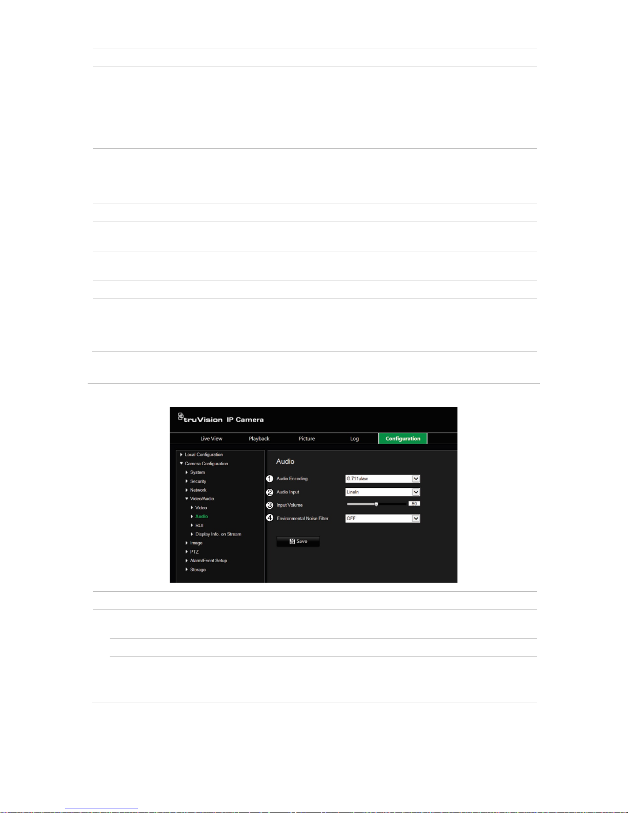
Figure 6: Audio settings menu
Note: This feature is only available for those camera models that support audio.
Parameter Description
1.
Audio Encoding
Select G.722.1, G.711ulaw, G.711alaw, MP2L2, G.726 or PCM as the
audio encoding type.
2.
Audio Input
Select “LineIn” or “MicIn” to select the type of audio input.
3.
Input Volume
Specify the volume from 0 to 100.
4.
Environmental Noise
Filter
Set it as OFF or ON. When enabled, the noise detected can be filtered.
Page 24
22 TruVision IP Compact PTZ Camera Configuration Manual
Figure 7: Display video analytics information menu
Description
When Dual-VCA mode is enabled, the camera sends video analytics results (metadata) to an NVR or
other platforms to generate a VCA alarm.
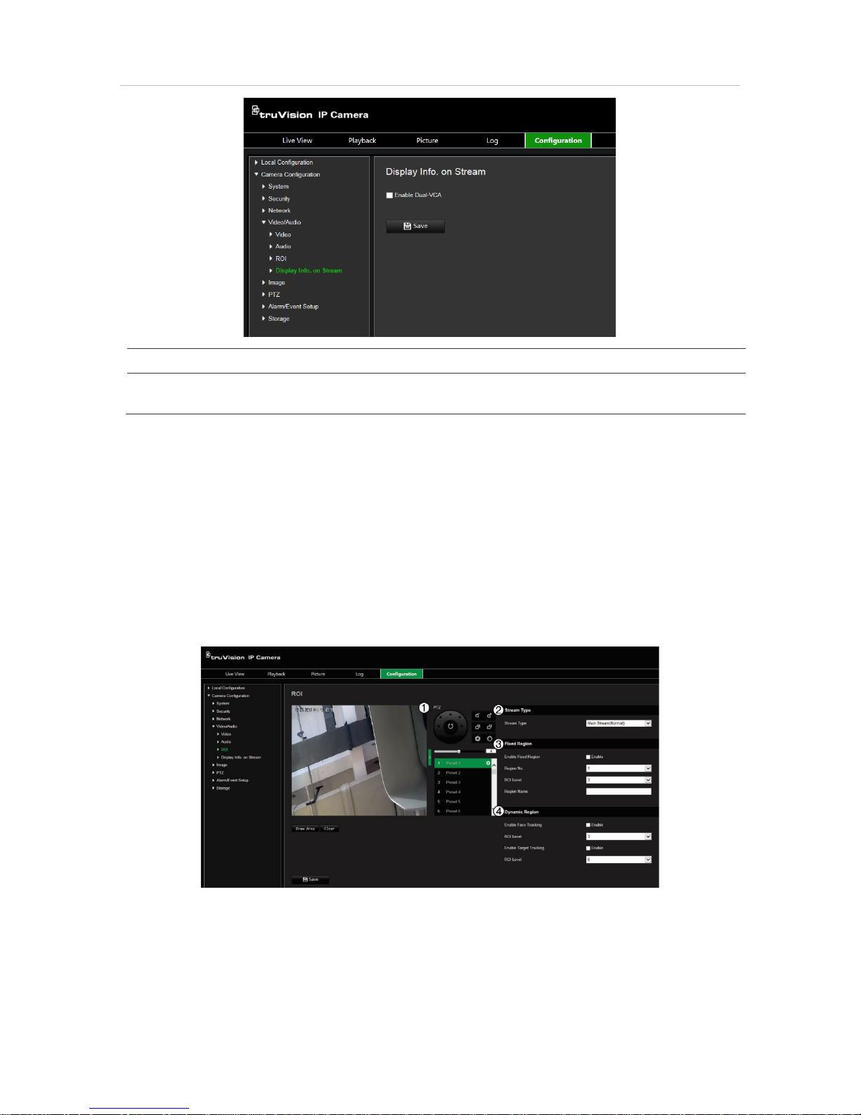
ROI encoding of an image
You can select an important area of detail or ROI (Region of interest) in a stream, such
as a number plate or face. The ROI area will have a higher quality image and the nonROI areas will have a lower image quality.
You can define up to eight ROIs.
To define an ROI:
1. From the menu toolbar, click Camera Configuration > Video/Audio > ROI.
2. Using the PTZ panel (1), move the lens to the desired location.
3. Select the stream type (2): main stream, substream, or third stream.
4. Enable Fixed Region (3). This lets you manually configure the image quality
enhancement level as well as name the region.
Region No.: Select the region. Default is 1.
Page 25

TruVision IP Compact PTZ Camera Configuration Manual 23
ROI Level: Choose the image quality enhancing level. Default is 6.
Region Name: Enter the desired region name.
5. Using the mouse, draw an area on the image.
6. Enable Face Tracking or Target Tracking (4), if required. This is an intelligent
analysis feature that facilitates auto-tracking. Select the ROI level. Default is 6.
7. Repeat steps 2 to 6 to set other regions. Up to eight regions can be set.
8. Click Save to save changes.
PTZ parameters
The following sections explain how to configure the different PTZ parameters.
Initial position
The initial position is the PTZ home coordinates. It can be the factory default position or
you can customize the initial position to your own requirements.
To set the initial position:
1. From the menu toolbar, click Camera Configuration > PTZ > Initial Position.
2. Click the PTZ control buttons to find a position as the initial position of the camera.
You can also call a defined preset and set it as the initial position.
3. Click Set to save the position.
To call and delete the initial position:
Click Call to call the initial position. Click Clear to delete the initial position and
restore the factory default initial position.
Basic PTZ parameters
You can configure the PTZ parameters, such as proportional pan, pr es et fre ezing,
preset speed, keyboard control speed, auto scan speed, and PTZ OSD.
To define basic PTZ parameter s:
1. From the menu toolbar, click Camera Configuration > PTZ > Basic Settings.
Page 26

24 TruVision IP Compact PTZ Camera Configuration Manual
2. Configure the following settings:
1. Basic Settings:
Proportional Pan If you enable this function, the pan/tilt speeds change according to
the amount of zoom. When there is a large amount of zoom, the
pan/tilt speed will be slower for keeping the image from moving too
fast on the live view image.
Preset Freezing This function enables live view to switch directly from one scene
defined by a preset to another, without showing the middle areas
between the presets. This helps ensure surveillance efficiency. It
can also reduce the use of bandwidth in a digital network system.
Note: Preset freezing function is invalid when calling up a shadow
tour.
Preset Speed: You can set the speed of a defined preset from 1 to 8.
Manual Control Speed The manual control speed can be set as Compatible, Pedestrian,
Non-motor Vehicle, Motor Vehic le or Auto.
Compatible: The control speed is same as the Keyboard Control
Speed.
Pedestrian: Choose the Pedestrian when you monitor the
pedestrians.
Non-motor Vehicle: Choose the Non-motor Vehicle when you
monitor the non-motor vehicles.
Motor Vehicle: Choose the Motor Vehicle when you monitor the
motor vehicles.
Auto: You are recommended to set it as Auto when the application
scene of the speed dome is complicated.
Keyboard Control Speed Define the speed of PTZ control by a keyboard as Low, Normal or
High.
Page 27

TruVision IP Compact PTZ Camera Configuration Manual 25
Auto Scan Speed The camera provides five scan modes: auto scan, tilt scan, frame
scan, random scan and panorama scan. The scan speed can be
set from level 1 to 40.
Max. Tilt Angle You can set the maximum tilt angle of the lens. There are sixteen
options: -15 to 90, -14 to 90, -13 to 90, -12 to 90, -11 to 90, -10 to
90, -9 to 90, -8 to 90, -7 to 90, -6 to 90, -5 to 90, -4 to 90, -3 to 90, -
2 to 90, -1 to 90, 0 to 90.
Zooming Speed You can vary the zooming speed. The zooming speed can be set
from level 1 to 3.
2. PTZ OSD:
Set the on-screen display duration of the PTZ status.
Zoom Status Set the OSD duration of zooming status as 2 seconds, 5 seconds,
10 seconds, Always Close, or Always Open
PT Status Set the azimuth angle display duration while panning and tilting as 2
seconds, 5 seconds, 10 seconds, Always Close, or Always Open.
Preset Status Set the preset name display duration while calling the preset as 2
seconds, 5 seconds, 10 seconds, Always Close, or Always Open.
3. Power-off Memory: The dome resumes its previous PTZ status or actions after it
restarts from a power off. You can set the time point at whic h the
dome resumes its PTZ status. You can set it to resume at 30
seconds, 60 seconds, 300 seconds, or 600 seconds before power
off.
3. Click Save to save changes.
Limit camera movement
The camera can be programmed to move only within a defined area. It can be limited in
how much it can move left/right and up/down. This can be useful when you do not want
an area, such as a neighboring building, to be included in the camera view.
To define the limit stop parameters:
1. From the menu toolbar, click Camera Configuration > PTZ > Limit.
Page 28

26 TruVision IP Compact PTZ Camera Configuration Manual
2. Click the Enable Limit checkbox to enable the limit function.
3. Click the Set button and use the PTZ control panel to set the limits of the camera
movement. You can also call up defined presets and set them as the limits of the
camera.
Click Clear to delete the set limits.
4. Select the limit type.
Manual Stops: When manual limit stops are set, you can operate the PTZ control
panel manually only within the restricted surveillance area.
Scan Stops: When scan limit stops are set, the random scan, frame scan, auto
scan, tilt scan, panorama scan are performed only within the restricted surveillance
area.
Note: The option Manual Stops has priority over Scan Stops. If these two functions
are set at the same time, only Manual Stops is enabled.
The status of the camera movement is displayed under Type Status as Not Limited
or Limited. The limits changes are saved automatically
5. Click Save to save changes.
Scheduled tasks
You can configure the camera to perform a specific action automatically during a userdefined time period.
Page 29

TruVision IP Compact PTZ Camera Configuration Manual 27
To define a scheduled task:
1. From the menu toolbar, click Camera Configuration > PTZ > Scheduled Tasks.
2. Check the checkbox of Enable Scheduled Task.
3. Choose the task type from the drop-down list. You can choose from one of the
following:
OFF
Auto Scan
Frame Scan
Random Scan
Preset Tour
Shadow Tour
Preset
Panorama Scan
Tilt Scan
Dome Reboot
Dome Adjust
Aux Output
Set the schedule by dragging the mouse pointer on the time bar o f the des i red day.
—Or–
Click the time bar of the desired day. The pop-up Timing Tasks window appears.
Select the desired task from the drop-down list and set its schedule:
Enter the task start time (hour and
minutes)
Enter the task end time (hour and
minutes)
Click Save to save the settings. Select more tasks and their schedule, if desired.
Note: The color of the scheduled period is that of the selected task type. Multiple
task schedules can be set for each day.
4. Set the Dwell Time. You can set the dwell time in seconds (a period of inactivity)
before the camera starts the scheduled tasks.
Page 30

28 TruVision IP Compact PTZ Camera Configuration Manual
5. Click Save to save changes.
Park actions
This is the action that will run automatically after the dwell time. A park action can be,
for example, a scan, preset, preset tour, or a shadow tour.
Note: The Scheduled Tasks function (see page 26) has priority over the Park Action
function. If these two functions are set at the same time, only Scheduled Tasks is
enabled.
To define a park action:
1. From the menu toolbar, click Camera Configuration > PTZ > Park Action.
2. Select Enable Park Action.
3. Set the Dwell Time, which is the inactivity time of the dome before it starts the park
action.
4. Select an action from the Action Type drop-down list. You can choose from one of
the following:
Auto Scan
Frame Scan
Random Scan
Preset Tour
Shadow Tour
Preset
Panorama Scan
Tilt Scan
5. If you select Preset Tour, Shadow Tour or Presets as Action Type, you need to
select Action Type ID from the drop-down list.
6. Click Save to save changes.
Page 31

TruVision IP Compact PTZ Camera Configuration Manual 29
Privacy masks
Privacy masks let you conceal sensitive areas (such as neighboring windows) to protect
them from view on the monitor screen and in the recorded video. The masking appears
as a blank area on screen. You can create up to 24 privacy masks per camera.
Note: There may be a small difference in size of the privacy mask area depending on
whether local output or the web browser is used.
To add privacy mask area:
1. From the menu toolbar, click Camera Configuration > PTZ > Privacy Mask.
2. Select Enable Privacy Masks (1).
3. Using the PTZ control buttons, point the camera at the desired area, or select a
predefined preset position, where you want to set the privacy mask.
4. Click the Draw Area button (2). Click and drag the mouse in the live video window
to draw the mask area.
5. Click Stop Drawing to finish drawing, or click Clear All to clear all of the areas you
set without saving them.
6. Click Add (3) to add the area. Enter its name, color, and active zoom ratio. Each
mask can be individually set.
Page 32

30 TruVision IP Compact PTZ Camera Configuration Manual
Note: The active zoom ratio is the magnification level the camera will zoom into
when motion is detected.
7. Click Save to save changes.
Clear PTZ configurations
Use the PTZ configurations menu to clear all presets, preset tours, shadow tours,
privacy masks, PTZ limits, scheduled tasks, and park actions.
To clear PTZ configurations:
1. From the menu toolbar, click Camera Configuration > PTZ > Clear Config.
2. Select the options that you want to clear:
Select All
Clear All Presets
Clear All Presets Tour
Clear All Shadow Tour
Clear All Privacy Masks
Clear All PTZ Limited
Clear All Scheduled Tasks
Clear All Park Action
3. Click Save to save changes.
Intelligent tracking
Intelligent tracking is used to track a moving object or person in a selected region.
To define intelligent tracking:
1. From the menu toolbar, click Configuration > PTZ > Intelligent Tracking.
Page 33

TruVision IP Compact PTZ Camera Configuration Manual 31
2. Select Enable Intelligent Tracking.
3. Using the PTZ control buttons, point the camera at the desired area, or select a
predefined preset position, where you want to set intelligent tracking.
4. Set the duration time. This is the time during which the camera follows the moving
object or person. You can select up to 300 seconds.
5. Set the zoom ratio (2). This is the zoom level used when you start to track the
person or object.
6. Click Save to save changes.
Prioritize PTZ
The PTZ dome can be controlled by network and RS-485 signals. You can set the
control priority of these two signals.
To define Prioritize PTZ:
1. From the menu toolbar, click Camera Configuration > PTZ > Prioritize PTZ.
Page 34

32 TruVision IP Compact PTZ Camera Configuration Manual
2. Select Network or RS-485 from the drop-down list.
3. Set the delay time (the range is between 2 and 200 s).
4. Click Save to save changes.
Overlay text
You can add up to eight lines of text on screen. This option can be used, for example,
to display emergency contact details. Each text line can be positioned anywhere on
screen. See Figure 8 below.
Page 35

TruVision IP Compact PTZ Camera Configuration Manual 33
Figure 8: Text overlay menu
To add on-screen text:
1. From the menu toolbar, click Camera Configuration > Image > OSD Settings.
2. Select the check box for the first line of text and enter the desired text in the text
box.
3. Use the mouse to click and drag the red text in the live view window to adjust the
text overlay position.
4. Repeat steps 2 to 4 for each extra line of text, selecting the next string number.
5. Click Save to save changes.
Video image
You may need to adjust the camera image depending on the camera model or location
background in order to get the best image quality. You can adjust the brightness,
contrast, saturation, hue, and sharpness of the video image.
Use this menu to also adjust camera behavior parameters such as exposure time, iris
mode, video standard, day/night mode, image flip, WDR, digital noise reduction, white
balance, and indoor/ou tdoor mo de. See Figure 9 below for more information.
Click the Default button at the bottom of the screen to return all settings to factory
default values.
Page 36

34 TruVision IP Compact PTZ Camera Configuration Manual
Figure 9: Camera image settings menu
Parameter Description
1.
Image Adjustment
Brightness
, Contrast
S
aturation, Sharpness
Modifies the different elements of picture quality by adjusting the
position of the values for each of parameter.
2.
Exposure Settings
Exposure Mode
The Exposure Mode can be set to Auto, Iris Priority, Shutter Priority,
and
Manual.
Auto: The iris, shutter and gain values will be adjusted automatically
according to the brightness of the environment.
Iris Priority: The value of iris needs to be adjusted manually. The
shutter and gain values will be adjusted automatically according to the
brightness of the environment.
Shutter Priority: The value of shutter needs to be adjusted manually.
The iris and gain values will be adjusted automatically according to the
brightness of the environment.
Manual: You can adjust the values of Gain, Shutter, and Iris manually.
Limit
Gain This feature is used to adjust the image
gain. The value ranges from 0 to
100.
Page 37

TruVision IP Compact PTZ Camera Configuration Manual 35
Parameter Description
Slow Shutter
The shutter speed controls the length of time that the aperture is open to
let light into the camera through the lens. A slow shutter speed means it
is open for longer. Select On or Off.
Slow Shutter Level
If Slow Shutter is enabled, use this feature to adjust the shutter speed.
Default value is Slow Shutter*2.
3.
Focus Settings
Focus Mode If the camera supports an electronic lens, you can set the focus mode
as Manual, Auto or Semi-auto.
Auto: The camera focus is adjusted automatically.
Manual: You can control the lens by adjusting the zoom, focus, lens
initialization, and auxiliary focus via the PTZ control interface. Default is
Manual.
Semi-auto: The camera focuses automatically only once after panning,
tilting and zooming.
Minimum Focus Distance
This function is used to set the limit of the minimum focus distance. The
value can be set to 10 cm, 50 cm, 1.0m, 1.5 m, 3 m, 6 m, 10 m, or
20 m.
4.
Day/Night Switch
Day/Night Switch
Defines whether the camera is in day or night mode. The day (color)
option could be used, for example, if the camera is located indoors
where light levels are always good.
Select one of the options:
Day: Camera is always in day mode.
Night: Camera is always in night mode.
Auto: The camera automatically detects which mode to use.
Scheduled-Switch: Select the start and end times for day mode
5.
Backlight Settings
BLC
If you focus on an object against strong backlight, the object will be too
dark to be seen clearly. BLC compensates light to the object in the front
to make it clear. Off, Up, Down, Left, Right, and Center are selectable.
WDR
When enabled, this feature (wide dynamic range) allows you to see
details of objects in shadows or details of objects in bright areas of
frames that have high contrast between light and dark areas. Default is
Off.
HLC
Highlight compensation (HLC) is a camera technology that detects if
there are any strong spots of light and compensates for the area as
needed to produce clearer images. Used to read, for example, car
number-plates in streets or parking lots at night. Default is Off.
6.
White Balance
White Balance
White balance (WB) tells the camera what the color white looks like.
Based on this information, the camera will then continue to display all
colors correctly even when the color temperature of the scene changes
such as from daylight to fluorescent lighting, for example. Select one of
the options:
MWB: Manually adjust the color temperature to meet your own
requirements.
Outdoor: Apply for outdoor environments.
Indoor: Apply for indoor environments.
Page 38

36 TruVision IP Compact PTZ Camera Configuration Manual
Parameter Description
Fluorescent Lamp: Apply for scene where there are fluorescent lamps
installed near the camera.
Sodium Lamp: Apply for scene where there are incandescent lamps
near the camera.
ATW: White balance is continuously being adjusted in real-time
according to the color temperature of the sc ene illumination.
Auto: White balance is determined automatically.
7.
Image Enhancement
Digital Noise Reduction
Digital noise reduction (DNR) reduces noise, especially in low light
conditions, to improve image performance. Select one of the options:
Normal: Standard DNR. Default.
Advanced: Set up the Space DNR level and the Time DNR level.
Space DNR level is used to reduce static noise, but if you configure a
higher value, the image may be not clear. Time DNR level is used to
reduce dynamic noise. If you configure a
higher value, the moving object
may have an obvious shadow.
OFF: Disable the function.
Noise Reduction Level
Only available when DNR is set to Normal Mode. Set the level of noise
reduction in the Normal Mode. Higher value has a stronger noise
reduction. Default is 50.
Defog
Mode You can enable the defog function when the environment is foggy and
the image is misty. It enhances the subtle details so that the image
appears clearer. Default is Off.
EIS
Electrical Image Stabilizer (EIS) reduces the effects of vibration in a
video. Default is Off.
8.
Video Adjustment
Mirror
It mirrors the image so you can see it inversed. Center, or OFF are
selectable.
Video Standard
50 Hz and 60 Hz are selectable. Select the standard according to the
different video standards; normally 50 Hz for PAL standard and 60 Hz for
NTSC standard.
Capture Mode
Set the desired frame rate to meet the different demands of field of view
and resolution. A higher frame rate may be required in a location with a
lot of movement (such as a money depot).
9.
Other
Lens Initialization
Enable the option so that the lens operates the movements for
initialization. Default is Disabled.
Zoom Limit
Set the limit of the maximum value of zooming.
Note: Not all models support all these parameter settings.
OSD
In addition to the camera name, the camera also displays the system date and time on
screen. You can also define how the text appears on screen.
Page 39

TruVision IP Compact PTZ Camera Configuration Manual 37
Figure 10: OSD settings menu
To position the date/time and name on screen:
1. From the menu toolbar, click Camera Configuration > Image > OSD Settings.
2. Select the Display Name box to display the camera’s name on screen. You can
modify the default name in the text box of Camera Name.
3. Select the Display Date check box to display the date/time on screen.
4. Select the Display Week check box to include the day of the week in the on-screen
display.
5. Select the time format from the Time format list box.
6. Select the date format from the Date format list box.
7. Select a display mode for the camera from the Display Mode list box. Display
modes include:
• Transparent & Not flashing. The image appears through the text.
• Transparent & Flashing. The image appears through the text. The text flashes
on and off.
• Not transparent & Not flashing. The image is behind the text. This is default.
• Not transparent & Flashing. The image is behind the text. The text flashes on
and off.
8. Select the OSD size that you want.
9. Select the font color: Black & White Self-adaptive or Custom. If Custom is selected,
click the color palette icon and select the desired color.
10. Using the mouse, place the red OSD text box in the desired positon on screen.
11. Click Save to save changes.
Note: If you set the display mode as transparent, the text varies according the scenery.
With some backgrounds, the text may be not clear.
Page 40

38 TruVision IP Compact PTZ Camera Configuration Manual
Image parameters switch
You can configure Link to Preset or Scheduled-Switch in this interface. Link to
Preset: Set the time period and linked scene for the preset and check the
corresponding checkbox to go to the linked scene in the configured time period.
Scheduled-Switch: Set the time period and linked scene and it will go to the linked
scene in the configured time period when you check the corresponding checkbox.
Figure 11: Image parameters switch menu
To set the Image Parameters Switch:
1. From the menu toolbar, click Camera Configuration > Image > Image Parameters
Swtich.
2. Select Link to Preset or Scheduled-Switch. (Only one function can be enabled at
the same time.)
3. To set up the image parameter swi tc h based on presets, enable Link to Preset.
Select a predefined preset fro m the drop-down list (see “Using presets” on page 72
for information on setting up a preset).
Select a period check box and set the start and end time periods as well as the
linked scene. Up to four periods can be configured for a selected preset.
4. To set up the image parameter swi tc h based on sch eduled periods, enable
Scheduled-Switch.
Select a period check box and set the start and end time periods and linked scene.
Up to four scheduled periods can be configured.
5. Click Save to save changes.
Note: The two functions are not enabled by default.
Page 41

TruVision IP Compact PTZ Camera Configuration Manual 39
Motion detection alarms
You can define motion detecti on al arms to detect motion when the camera is not
moving. A motion detection alarm refers to an alarm triggered when the camera detects
motion. However, the motion alarm is only triggered if it occurs during a programmed
time schedule.
Select the level of sensitivity to motion as well as the target size so that only objects
that could be of interest can trigger a motion recording. For example, the motion
recording is triggered by the movement of a person but not that of a cat.
You can define the area on screen where the motion is detected, the level of sensitivity
to motion, the schedule when the camera is sensitive to detecting motion as well as
which methods are used to alert you to a motion detection alarm.
You can also enable dynamic analysis for motion. When there is motion, the area will
be highlighted in green.
Defining a motion detection alarm requires the following tasks:
Figure 12: Motion detection window
1. Area Settings: Define the on-screen area that can trigger a motion detection alarm
as well as the detection sensitivity level (see Figure 12, item 1).
2. Arming Schedule: Define the schedule which the system detects and records
motion (see Figure 12, item 2). See “Recording schedule” on page 53 for further
information.
3. Actions: Specify the method of response to the alarm (see Figure 12, item 3).
To set up motion detection:
1. From the menu toolbar, click Camera Configuration > Alarm/Event Setup >
Motion Detection.
Page 42

40 TruVision IP Compact PTZ Camera Configuration Manual
2. Select Enable Motion Detection. Select Enable Dynamic Analysis for Motion if
you want to see in live view where the det ec te d motion has occurred.
Note: Deselect the “Enable Motion Detection” option to disable the motion detection
alarm.
3. Click Draw Area. Click and drag the mouse on the live video image to draw an area
sensitive to motion detection.
4. Click Stop Drawing to finish drawing. Click Clea r All to delete all areas marked and
restart drawing.
5. Move the Sensitivity slider to set the sensitivity of the detection. All areas will have
the same sensitivity level.
6. Drag and click on the time bar to edit the arming schedule.
Enter the start time (hour and
minutes)
Enter the end time (hour and minutes)
6. You can copy the schedule to other days or to the whole week by clicking .
7. Specify the actions when an event occurs. Check one or more response actions for
the system when a motion detection alarm is triggered.
Notify
Surveillance Center Send an exception or alarm signal to remote management
software when an event oc c urs .
Send
Email Sends an email to a s
pecified address when there is a motion
detection alarm.
Upload
to FTP/Memory
Card
/NAS
Capture the image when an alarm is triggered and upload the
picture to NAS or FTP server.
Trigger
Recording Triggers the recording to start in the camera.
Trigger Alarm Output
Trigger external alarm outputs when an event occurs. Select
one of the options: Select Trigger Alarm Output, A->1, or A>2.
Note: This option is only supported by cameras that support
alarm output.
8. Click Save to save changes.
Page 43

TruVision IP Compact PTZ Camera Configuration Manual 41
Tamper-proof alarms
You can configure the camera to trigger an alarm when the lens is covered and to take
an alarm response action.
To set up tamper-proof alarms:
1. From the menu toolbar, click Camera Configuration > Alarm/Event Setup >
Tamper-proof.
2. Select the Enable Tamper-proof check box.
3. Move the Sensitivity slider to set the detection sensitivity.
4. Set the arming schedule for tam per -proof alarms. The arming schedule
configuration is the same as that for motion detection. See “M otion detection
alarms” on page 39 for more information.
5. Select the actions to be used for the tamper-proof detection. The options are:
Notify
Surveillance Center Send an exception or alarm signal to remote management
software when an event oc c urs .
Send
Email Sends an email to a s
pecified address when there is a motion
detection alarm.
Trigger Alarm Output
Trigger external alarm outputs when an event occurs. Select
one of the options: Select Trigger Alarm Output, A->1, or
A->2.
Note: This option is only supported by cameras that support
alarm output.
6. Click Save to save changes.
Alarm Input
To define an external alarm input:
1. From the menu toolbar, click Camera Configuration > Alarm/Event Setup >
Alarm Input.
Page 44

42 TruVision IP Compact PTZ Camera Configuration Manual
2. Select the Alarm Input No. and the Alarm Type. The alarm type can be NO
(Normally Open) or NC (Normally Closed). Enter a name for the alarm input.
3. Set the arming schedule for the alarm input. See “Motion detection alarms” on page
39 for more information on scheduling.
4. Select the actions to be used for the alarm input. The options are:
Normal Actions: Notify Surveillance Center, Send Email, Upload to FTP/Memory
Card/NAS
Other Actions: Trigger Alarm Output, Trigger Recording, PTZ Linking
For Trigger Alarm Output the options are: Trigger Alarm Output, A->1, or A->2.
For PTZ Linking the opt ions are: Preset No., Preset Tour No., or Shadow Tour No.,
and enter the desired number.
5. To copy the alarm setup to another alarm input, select one of the options shown
under Copy to Alarm.
6. Click Save to save changes.
Alarm Output
To define an alarm output:
1. From the menu toolbar, click Camera Configuration > Alarm/Events Setup>
Alarm Output.
Page 45

TruVision IP Compact PTZ Camera Configuration Manual 43
2. Select one alarm output channel from the Alarm Output drop-down list. You can
also set a name for the alarm output .
3. The delay time can be set to 5 s, 10 s, 30 s, 1 min, 2 min, 5 min, 10 min or Manual.
The delay time refers to the time duration that the alarm output remains in effect
after alarm occurs.
4. Set the arming schedul e for the al ar m out put. See “Motion detection alarms ” on
page 39 for more informati o n on scheduling.
5. To copy the alarm setup to another alarm input, select one of the options shown
under Copy to Alarm.
6. Click Save to save changes.
Exception alarms
You can set up the camera to notify you when irregular events occur and how you
should be notified. These exception alarms include:
• HDD Full: All recording space of NAS is full.
Note: As the SD card is in overwrite mode by default, it will never trigger a HDD Full
alarm.
• HDD Error: Errors occurred while files were being written to the storage, no storage
or storage had failed to init ial i ze.
• Network Disconnected: Disconnected network cable.
• IP Address Conflicted: Conflict in IP address setting.
Page 46

44 TruVision IP Compact PTZ Camera Configuration Manual
• Invalid Login: Wrong user ID or password used to login to the cameras.
To define exception alarms:
1. From the menu toolbar, click Camera Configuration > Alarm/Event Setup >
Exception.
2. Under Notification Type, select one of the exception alarms from the drop-down
list. The options are: HDD Full, HDD error, Network Disconnected, IP Address
Conflicted, Invalid Login.
3. Select the desired the actions: Notify Surveillance Center, Send em ai l , or Tri g g er
Alarm Output. If “Trigger Alarm Output” is selected, select which type is required:
Select Trigger Alarm Output, A->1, or A->2.
4. Repeat steps 2 and 3 for each of the exception type alarms to be configured.
5. Click Save to save changes.
Audio exception detection
Audio exception detection detects sounds that are above a defined threshold.
To set up audio exception detection:
1. From the menu toolbar, click Camera Configuration > Alarm/Event Setup >
Audio Exception Detection.
Page 47

TruVision IP Compact PTZ Camera Configuration Manual 45
2. Check Enable for Audio Loss Exception.
3. Check Enable for Sudden Increase of Sound Intensity Detection and set the
sensitivity and sound intensity threshold.
4. Select Sudden Decrease of Sound Intensity Detection and set the sensitivity.
5. Set the arming schedule for the alarm input. See “To set up motion detection” on
page 39 on page for more infor mation.
6. Select the actions to be used. The options are:
Notify
Surveillance Center Send an exception or alarm signal to remote management
software when an event oc c urs .
Send Email
Sends an email to a s
pecified address when there is a motion
detection alarm.
Trigger
Recording Triggers the recording to start in the camera.
Trigger Alarm Output
Trigger external alarm outputs when an event occurs. Select
one of the options: Select Trigger Alarm Output, A->1, or
A->2.
Note: This option is only supported by cameras that support
alarm output.
1. Click Save to save changes.
Face detection
When the face detection function is enabled, the camera can detect a human face that
is moving towards it, triggering a configurable response. The camera can only detect a
face looking directly into the camera, not side views. This feature is best suited when
the camera is in front of a door or is located in a narrow corridor.
Page 48

46 TruVision IP Compact PTZ Camera Configuration Manual
To set up face detection:
1. From the menu toolbar, click Camera Configuration > Alarm/Event Setup> Face
Detection.
2. Select Enable Face Detection.
3. Select Enable Dynamic Analysis for Face Detection if you want the fac e detec t ed
to be marked with a green rectangle in live view.
Note: if you do not want the detected face marked with the green frame, select
Disable from Local Configuration > Browser Configuration > Live View
Parameters > Enable Meta Data Overlay.
4. Configure the sensitivity of the face detection. The range is between 1 and 5.
5. Set the arming schedule for the face detecti on. The arming schedule configuration is
the same as that for motion detection. See “Motion detec ti on alar m s ” on page 39 for
more information.
6. Select the actions to be used for the face detection. The options are:
Notify
Surveillance Center Send an exception or alarm signal to remote management
software when an event oc c urs .
Send
Email Sends an email to a s
pecified address when there is a motion
detection alarm.
Upload to FTP/Memory
Card/NAS
Capture the image when an alarm is triggered an
d upload the
picture to NAS or FTP server.
Trigger
Recording Triggers the recording to start in the camera.
Page 49

TruVision IP Compact PTZ Camera Configuration Manual 47
Trigger Alarm Output
Trigger external alarm outputs when an event occurs. Select
one of the options: Select Trigger Alarm Output, A->1, or A>2.
Note: This option is only supported by cameras that support
alarm output.
7. Click Save to save changes.
Intrusion detection
You can set up an area in the surveillance scene to detect when intrusion occurs. If
someone enters the area, a set of alarm actions can be triggered.
To set up intrusion detection:
1. From the menu toolbar, click Camera Configuration > Alarm/Event Setup>
Intrusion Detection.
2. Select Enable to enable the functi o n.
3. Select Dra w Ar ea and then draw a rectangle on the image as the defense region.
When you draw the rectangle, all lines should connect end-to-end to each other. Up
to four areas are supported. Click Clear to clear the areas you have drawn. The
defense region parameters can be set up separately.
Note: The area can only be quadrilateral.
4. Choose the region to be configured.
Threshold: This is the time threshold that the object remains in the region. If you
set the value as 0, the alarm is triggered immediately after the object enters the
region. The range is between 0 and 10.
Sensitivity: The sensitivity value defines the size of the object that can trigger the
alarm. When the sensitivity is high, a small object can trigger the alarm. The range
is between 1 and 100.
Detection Target: You can select Human, Vehicle, or All (Human &Vehicle) as the
detection target from the dropdown list. If Human is selected, only people will be
Page 50

48 TruVision IP Compact PTZ Camera Configuration Manual
identified as detectio n objec ts . If Vehicle is selected, only vehicles will be identified
as detection objects.
5. Set the arming schedule for the intrusion detection. The arming schedule
configuration is the same as that for motion detection. See “Motion detection
alarms” on page 39 for more information.
6. Select the actions to be used for the intrusion detection. The options are:
Notify
Surveillance Center Send an exception or alarm signal to remote management
software when an event oc c urs .
Send
Email Sends an email to a s
pecified address when there is a motion
detection alarm.
Upload to FTP/Memory
Card/NAS
Capture the image when an alarm is triggered and upload the
picture to NAS or FTP server.
Intelligent Tracking
Triggers the intelligent tracking function
Trigger
Recording Triggers the recording to start in the camera.
Trigger Alarm Output
Trigger external alarm outputs when an event occurs. Select
one of the options: Select Trigger Alarm Output, A->1, or
A->2.
Note: This option is only supported by cameras that support
alarm output.
7. Click Save to save changes.
Line crossing detection
This function can be used to detect people, vehicles and objects crossing a pre-defined
line or an area on-screen. The line crossing direction can be set as unidirectional or
bidirectional. Unidirectional is crossing the line from left to right or from right to left.
Bidirectional is crossing the line from both directions.
A series of actions can be triggered if an object is detected crossing the line.
To set up line crossing detection:
1. From the menu toolbar, click Camera Configuration > Alarm/Event Setup> Line
Crossing Detection.
Page 51

TruVision IP Compact PTZ Camera Configuration Manual 49
2. Select Enable to enable the function.
3. Select Dra w Ar ea and a crossing plane will show on the image.
4. Click the line and two red squares appear at each end. Drag one of the red squares
to define the arming area.
Select the direction as A<->B, A ->B, or B->A from the drop down menu:
A<->B: Only the arrow on the B side is displayed. When an object moves across the
plane in both directions, it is detected and alarms are triggered.
A->B: Only an object crossing the pre-defined line from the A to the B side can be
detected and trigger an alarm.
B->A: Only an object crossing the pre-defined line from the B to the A side can be
detected and trigger an alarm.
5. Choose the sensitivity level between 1 and 100.
6. Choose the Detection Target from All, Human or Vehicle.
7. If desired, select another line crossing area to configure from the dropdown menu.
Up to four line crossing areas can be configured.
8. Set the arming schedule for the line crossing detection. The arming sc hed ul e
configuration is the same as that for motion detection. See “Motion detection
alarms” on page 39 for more information.
9. Select the actions to be used for the line crossing detectio n. The options are:
Notify
Surveillance Center Send an exception or alarm signal to remote management
software when an event oc c urs .
Send
Email Sends an email to a s
pecified address when there is a motion
detection alarm.
Upload to FTP/Memory
Card/NAS
Capture the image when an alarm is triggered and upload the
picture to NAS or FTP server.
Intelligent Tracking
Triggers the intelligent tracking function
Trigger
Recording Triggers the recording to start in the camera.
Page 52

50 TruVision IP Compact PTZ Camera Configuration Manual
Trigger Alarm Output
Trigger external alarm outputs when an event occurs. Select
one of the options: Select Trigger Alarm Output, A->1, or
A->2.
Note: This option is only supported by cameras that support
alarm output.
10. Click Save to save changes.
Region entrance detection
This function detects people, vehicles or other objects that enter a designated region
from outside the designated region. Certain actions can be configured to occur when
the alarm is triggered.
To set up region entrance detection :
1. From the menu toolbar, click Camera Configuration > Alarm/Event Setup> Region
Entrance Detection.
2. Select Enable to enable the function.
3. Select the region number to be configured.
4. Click Draw Area, and then draw a rectangle on the image as the designated region.
When you draw the rectangle, all lines should connect end-to-end to each other. Up
to four areas are supported. Click Clear to clear the areas you have drawn. The
designated region parameters can be set up separately.
Note: The area can only be quadrilateral.
5. Set the sensitivity level.
The sensitivity value defines the size of the object that can trigger the alarm. When
the sensitivity is high, a small object can trigger the alarm. The range is between 1
and 100.
6. Select the detection target from All, Human, or Vehicle.
Page 53

TruVision IP Compact PTZ Camera Configuration Manual 51
7. Set the arming schedule for the region entrance detection. The arming schedule
configuration is the same as that for motion detection. See “Motion detection
alarms” on page 39 for more information.
8. Select the actions to be used for the region entrance detect ion. The options are:
Notify
Surveillance Center Send an exception or alarm signal to remote management software
when an event occurs.
Send
Email Sends an email to a specified address when there is a motion
detection alarm.
Upload to FTP/Memory
Card/NAS
Capture the image when an alarm is triggered and upload the
picture to NAS or FTP server.
Intelligent Trackin
g Triggers the intelligent tracking function
Trigger
Recording Triggers the recording to start in the camera.
Trigger Alarm Output
Trigger external alarm outputs when an event occurs. Select one of
the options: Select Trigger Alarm Output, A->1, or A->2.
Note: This option is only supported by cameras that support alarm
output.
9. Click Save to save changes.
Region exiting detection
Region exiting detection function detects people, vehicle or other objects that exit from
a designated region, and certain actions can be configured to occur when the alarm is
triggered.
To set up region existing detection:
1. From the menu toolbar, click Camera Configuration > Alarm/Event Setup> Region
Existing Detection.
2. Select Enable to enable the function.
3. Click Draw Area, and then draw a rectangle on the image as the designated region.
When you draw the rectangle, all lines should connect end-to-end to each other. Up
Page 54

52 TruVision IP Compact PTZ Camera Configuration Manual
to four areas are supported. Click Clear to clear the areas you have drawn. The
designated region parameters can be set up separately.
Note: The area can only be quadrilateral.
4. Select the region to be configured.
Sensitivity: The sensitivity value defines the size of the object that can trigger the
alarm. When the sensitivity is high, a small object can trigger the alarm. The range
is between 1 and 100.
Detection Target: You can select human, vehicle, or all (human &vehicle) as the
detection target from the dropdown list. If Human is selected, only human beings will
be identified as detection objects and as well as Vehicle.6. Choose the Detection
Target from All, Human or Vehicle.
5. Set the arming schedule for the region existing detection. The arming schedule
configuration is the same as that for motion detection. See “Motion detection
alarms” on page 39 for more information.
6. Select the actions to be used for the region existing detection. The options are:
Notify
Surveillance Center Send an exception or alarm signal to remote management
software when an event oc c urs .
Send
Email Sends an email to a specified address when there
is a motion
detection alarm.
Upload to FTP/Memory
Card/NAS
Capture the image when an alarm is triggered and upload the
picture to NAS or FTP server.
Intelligent Tracking
Triggers the intelligent tracking function
Trigger
Recording Triggers the recording to start in the camera.
Trigger Alarm Output
Trigger external alarm outputs when an event occurs. Select
one of the options: Select Trigger Alarm Output, A->1, or A>2.
Note: This option is only supported by cameras that support
alarm output.
7. Click Save to save changes.
RS-485 settings
The RS-485 serial port is used to control the PTZ of the camera. Configuration of these
parameters should be done before you connect to any devices.
To set up RS-485 settings:
1. From the menu toolbar, click Camera Configuration > System > RS-485.
Page 55

TruVision IP Compact PTZ Camera Configuration Manual 53
2. Select the RS-485 port parameters.
Note: The Baud Rate, PTZ Protocol and PTZ Address should be the same as the
PTZ camera parameters.
3. Click Save to save changes.
Recording schedule
You can define a recording schedule for the camera in the “Record Schedule” w indow.
The recording is saved on to the SD card or NAS in the camera. The camera’s SD card
provides a backup in case of network failure.
The selected recording schedule applies to all alarm types.
Pre-record time
The pre-record time is set to start recording before the scheduled time or the event. For
example, if an alarm triggers recording at 10:00, and the pre- event time is set as 5
seconds, the camera starts to record at 9:59:55. The pre- event time can be configured
as No Pre-record, 5 s, 10 s, 15 s, 20 s, 25 s, 30 s, or not limited.
Post-record time
The post-record time is set to stop recording after the scheduled time or the event. For
example, if an alarm triggered recording ends at 11:00, and the post-event time is set
as 5 seconds, the camera records until 11: 00:05. The post-event time can be
configured as 5 s, 10 s, 30 s, 1 min, 2 min, 5 min, or 10 min.
To set up a recording schedule:
1. From the menu toolbar, click Camera Configuration > Storage > Record
Schedule.
Page 56

54 TruVision IP Compact PTZ Camera Configuration Manual
2. Select the pre and post-record times.
3. Enable overwrite, if required.
4. Select the stream type (main stream, substream, or third stream).
5. Click the Enable check box to enable recording.
Note: To disable recording, deselect the option.
6. Select one of the record types to record from the drop-down list box:
• Continuous: This is continuous recording.
• Motion: The video is recorded when the motion is detected.
• Alarm: The video is recorded when the alarm is triggered via the external alarm
input.
• Motion | Alarm: The video is recorded when the external alarm is triggered or
the motion is detected.
• Motion & Al a rm : The video is recorded when motion, alarms, and audio
exception detection are triggered at the same time.
7. Drag the time bar to edi t the recording schedule. Click on the selected time period
and the following window appears:
Enter the start time (hour and
minutes)
Enter the end time (hour and minutes)
6. Set the recording periods for the other days of the week if required.
Click to copy the recording periods to another day of the week.
7. Click OK and Save to save changes.
Note: If you set the record type to “Motion detection”, “Alarm” or other alarms such as
audio exception detection, you must also define the arming schedule in order to trigger
motion detection or alarm input recording.
Page 57

TruVision IP Compact PTZ Camera Configuration Manual 55
Format storage devices
Use the storage mana g ement window to display the capacity, free space available, and
the working status of the HDD of the NAS and the SD card in the camera. You can also
format these storage devices.
Before formatting the storage device, stop all recor di ng. Once formatting is completed,
reboot the camera as otherwise the device will not function properly.
If Overwrite is enabled, the oldest files are overwri tten when the storage beco m es full .
To format the storage devices:
1. From the menu toolbar, click Camera Configuration > Storage > HDD
Management.
2. Under HDD Management, check the desired storage device and click Initialize. A
window appears to check your formatting permission. Click OK to start formatting.
3. Define the quota storage capacity and percentage for snapshots and recordings in
the storage devices connected to the camera.
4. Click Save to save changes.
Page 58

56 TruVision IP Compact PTZ Camera Configuration Manual
NAS settings
You can use a network storage system (NAS) to remotely store recordings. To
configure record settings, please ensure that you have the network storage device
within the network.
The NAS disk should be available within the network and correctly configured to store
the recorded files, log files, etc.
Notes: Up to eight NAS disks can be connected to the camera.
To set up a NAS system:
1. From the menu toolbar, click Camera Configuration > Storage > Net HDD.
2. Enter the IP address of the network disk and the file path.
3. Configure the Mounting Type as NFS or SMB/CIFS. If you select SMB/CIFS, you
can enter the user name and password.
4. Click Save to save changes.
Snapshot parameters
You can configure scheduled snapshots and event-triggered snapshots. The captured
snapshots can be stored in the SD card (if supported) or the NAS. You can also upload
the snapshots to an FTP server.
Note: If you have configured the FTP settings and check Upload Picture in the FTP
tab, the snapshots will be uploaded to the FTP. If you also check Upload to
FTP/Memory Card/NAS for motion detection or alarm input, the snapshots will be
uploaded to the FTP when motion det ect ion or an alarm input is triggered.
Page 59

TruVision IP Compact PTZ Camera Configuration Manual 57
To set up snapshots:
1. From the menu toolbar, click Camera Configuration > Storage > Snapshot.
2. Check Enable Timing Snapshot to enable continuous snapshots. Chec k th e
Enable Event-triggered Snapshot to enable event-triggered snapshots.
3. Select the snapshot for mat (JPEG only), resolution and quality.
4. Set the time interval between two snapshots. The time interval can be in
milliseconds, seconds, minutes, hours, or days.
5. If Enable Event-Triggered Snapshot was selected, select the number of
snapshots to capture. For example, if you set the value as 4, the total number of the
snapshot will be multiples of four.
6. Click Save to save changes.
Page 60

58 TruVision IP Compact PTZ Camera Configuration Manual
Camera management
This chapter describes how to use the camera once it is installed and configured. The
camera is accessed through a web browser.
User management
This section describes how to manage users. You can:
Add or delete users
Modify permission
Modify passwords
Only the administrator can manage users. The administrator can create up to 31
individual users. When new users are added to the list, the administrator can modify
permissions and password of each user. See Figure 13 below.
Figure 13: User management window
Passwords limit access to the camera and the same password can be used by several
users. When creating a new user, you must give the user a password. There is no
default password provided for all users. Users can not modify their password, and only
the administrator can create or modify pas sword for a user.
Note: Keep the admin password in a safe place. If you forget it, please contact
technical support.
Page 61

TruVision IP Compact PTZ Camera Configuration Manual 59
Types of users
A user’s access privileges to the system are automatically defined by their user type.
There are three types of user:
Admin: This is the system administrator. The administrator can configure all
settings. Only the administrator can create and delete user accounts. Admin cannot
be deleted.
Operator: This user can only change the configuration of his/her own account. An
operator cannot create or delete other users.
User: This user has the permission of live view, playback and log search. However,
they cannot change any configuration settings.
Adding and deleting users
The administrator can create up to 15 users. Only the system administrator can create
or delete users.
To add a user:
1. In the Security folder, click the Users option to open its window.
2. Select the Add button. The user management window appears.
3. Enter a user name. The name can have up to 16 alphanumeric characters.
4. Select the type of user fro m the dr op-down list. The options are Viewer and
Operator.
Page 62

60 TruVision IP Compact PTZ Camera Configuration Manual
5. Assign the user a password. Passwords can have up to 16 alphanumeric
characters.
6. Assign permissions to users.
Basic permissions Camera permissions
Remote parameter settings
Remote log search/Interrogate working
status
Remote upgrade/format
Remote two-way audio
Remote shutdown/reboot
Remote notify surveil lance c enter /Trigger
alarm output
Remote video output control
Remote serial port control
Remote live view
Remote PTZ control
Remote manual record
Remote playback
7. Click OK to save changes.
To delete a user:
1. Select one user in the Users option.
2. Click the Delete button. A message box appears.
Note: Only the administrator can delete a user.
3. Click Save to save the changes.
Modifying user information
You can easily change the information about a user such as their name, password and
permissions.
To modify user information:
1. Select a user in the Users option.
2. Click the Modify button. The user management window appears
3. Change the information required.
Note: The user “Admin” can only be changed by entering the admin password.
4. Click Save to save changes.
RTSP authentication
You can secure the stream data of live view.
To define RTSP authentication:
1. From the menu toolbar, click Camera Configuration > Security > Authentication.
Page 63

TruVision IP Compact PTZ Camera Configuration Manual 61
2. Under RTSP Authentication, select digest or digest/basic to choose RTSP
authentication type.
3. Click Save to save the changes.
To define web authentication:
1. From the menu toolbar, click Camera Configuration > Security > Authentication.
2. Under WEB Authentication, select digest or digest/basic to choose web
authentication type.
3. Click Save to save the changes.
Page 64

62 TruVision IP Compact PTZ Camera Configuration Manual
IP address filter
This function permits you to restrict the IP addresses that can be accessed by the
camera.
To define an IP address filter:
1. From the menu toolbar, click Camera Configuration > Security > IP Address
Filter.
2. Check the Enable checkbox.
3. Select the type of IP address filter in the drop-down list, Forbidden or Allowed.
4. Click Add to add an IP address.
5. Click Modify or Delete to modify or delete the selected IP address.
6. Click Clear to delete all the IP addrsses.
7. Click Save to save changes.
Defining the security service
This function allows y ou to enable the invalid login lock.
To enable the invalid login lock:
1. From the menu toolbar, click Camera Configuration > Security > Security
Service.
Page 65

TruVision IP Compact PTZ Camera Configuration Manual 63
2. Check the checkbox of Enable Invalid Login Lock.
3. Click Save to save changes.
Note:
1. The IP address will be locked if the admin user performs seven failed user
name/password attempts (10 attempts for the operator/user).
2. If the IP address is locked, you can try to login the device after five minutes.
Restore default set tings
Use the Default menu to restore default settings to the camera. There are two options
available:
Restore: Restore all the parameters, except the IP parameters, to the default
settings.
Default: Restore all the parameters to the default settings.
Note: The video standard cannot be restored to default settings using Restore or
Default.
To restore default settings:
1. In the Camera Configuration folder, select the System tab.
2. Select the Maintain tab.
3. Click either Restore or Default. A window showing user authentication appears.
4. Enter the admin password and click OK.
5. Click OK in the pop-up message box to confirm restoring operation.
Page 66

64 TruVision IP Compact PTZ Camera Configuration Manual
Import/export a configuration file
To import/export configuration file:
1. In the Camera Configuration folder, select the System tab.
2. Select the Maintain tab.
3. Click Browse to select the local configuration file and then click Import to start
importing configuration file.
4. Click Device Parameters and set the saving path to save the configuration file.
Upgrade firmware
The camera firmware is stored in the flash memory. Use the upgrade function to write
the firmware file into the flash memor y.
You need to upgrade firmware when it has become outdated. When you upgrade the
firmware, all existing settings are unchanged. Only the new features are added with
their default settings.
To upgrade the firmware through the web browser:
1. Download on to your computer the latest firmware from our web site at:
www.interlogix.com/library
2. In the Camera Configuration folder, select the System tab.
3. Select the Maintain tab.
In the Maintenance tab, select the Firmware or Firmware Directory option. Then
click the Browse button to locate latest firmware file on your computer.
Firmware Directory: Locate the upgrading folder of the firmware files. The
camera selects the corresponding firmware file automatically.
Firmware: Locate the firmware file manually for the camera.
4. Click the Browse button to locate the latest file on your computer.
5. Click Upgrade. You will receive a prompt asking you to reboot the camera.
Reboot camera
The camera can be easily rebooted remotely.
To reboot the camera through the web browser:
1. In the Camera Configuration folder select th e System tab.
2. Select the Maintain tab.
3. Click the Reboot button to reboot the device.
4. Click OK in the pop-up message box to confirm reboot operation.
Page 67

TruVision IP Compact PTZ Camera Configuration Manual 65
System service
To set the live view connection:
1. From the menu toolbar, click Camera Configuration > System > System Service.
2. Input a number in text field as the upper limit of the remote connection number. For
example, when you specify the remote connection number as 10, then the 11th
remote connection cannot be es ta bl i shed.
3. Click Save button to activate the settings.
About
Click View License to select the Open Source Software License.
Page 68

66 TruVision IP Compact PTZ Camera Configuration Manual
Camera operation
This chapter describes how to use the camera once it is installed and configured.
Logging on and off
You can easily log out of the camera browser window by clicking the Logout button on
the menu toolbar. You will be asked each time to enter your user name and password
when logging in.
If you do not change the default admin password, the pop up window requesting that
you do so it will always pop up (see Figure 14 below).
Figure 14: Login window
Live view mode
Once logged in, click “Live View” on the menu toolbar to access live view mode. See
Figure 1 on page 9 for the description of the interface.
Playing back recorded video
You can easily search and play back recorded video in the playback interface.
Note: You must configure NAS or inser t SD card in the dome camer a to be able to use
the playback functions.
To search recorded video stored on the camera’s storage device for playback, click
Playback on the menu toolbar. The Playback window displays. See Figure 15 below.
Page 69

TruVision IP Compact PTZ Camera Configuration Manual 67
Figure 15: Playback window
Name Description
1
. Playback button Click to open the Playback window.
2
. Search calendar Click the day required to search.
3
. Search Start search.
4
. Set playback time Input the time and click to locate the playback point.
5
. Control playback Click to control how the selected file is played back: play, stop, slow
and fast forward playback.
6
. Archive functions Click these buttons for the following archive actions:
Capture a snapshot image of the playback video.
Start/Stop clipping video files.
7
. 3D zoom Click to enable 3D zoom.
8
. Audio Drag to adjust the volume.
9
. Timeline bar The timeline bar displays the 24-hour period of the day being played
back. It moves left (oldest) to right (newest). The bar is color-
coded to
display the type of recording.
Click a location on the timeline to move the cursor to where you want
playback to start. The timeline can also be scrolled to earlier or later
periods for play back.
Click to zoom out/in the timeline bar.
10
. Time moment Vertical bar shows where you are in the playback recording. The
current time and date are also displayed.
11
. Download functions
Download video files.
Page 70

68 TruVision IP Compact PTZ Camera Configuration Manual
Name Description
12
. Recording type The color code displays the recording type. Recording types are
schedule recording, alarms recording and manual recording.
The recording type name is also displayed in the current status
window.
To play back recorded video
1. Select the date and click the Search button. The searched video is displayed in the
timeline.
2. Click Play to start playback. While playing back a video, the timeline bar displays
the type and time of the recording. The timeline can be manually scrolled using the
mouse.
Note: You must have playback permission to playback recorded images. See
“Modifying user information” on page 60 to archive recorded video files.
3. Select the date and click the Search button to search for the required recorded file.
4. Click to search the video file.
5. In the pop-up window, check the box of the video file and click Download to
download the video files.
To archive a recorded video segment during playback:
1. While playing back a recorded file, click to start clipping. Click it again to stop
clipping. A video segment is created.
2. Repeat step 1 to create additional segments. The video segments are saved on
your computer.
Snapshots
Note: Follow the instructions under “Snapshot parameters” on page 61 to configure
snapshot capture parameters before using the Picture menu.
Click Picture to launch the snapshot searching interface. Use this menu to search for,
view, and download the snapshots stored in the camera’s SD card or in network
storage.
To search the snapshots:
1. Make a selection from the File Type drop-down list. Continuous, Motion, Alarm,
Line Crossing, and Intrusion Detection are selectable.
2. Click on the calendar icon in the Start Time and End Time boxes to select the start
time and end time.
3. Click Search to search the matched pictures.
4. Select the check box next to one or more snapshots and then click Download to
download the selected images.
Page 71

TruVision IP Compact PTZ Camera Configuration Manual 69
Searching event logs
You must configure NAS or insert a SD card in the PTZ camera to be able to use the
log functions.
The number of event logs that can be stored on NAS or SD card depends on the
capacity of the storage devices. When this capacity is reached, the system starts
deleting older logs. To view logs stored on storage devices, click Log on the menu
toolbar. The Log window appears. See Figure 16 below.
Note: You must have view log access rights to search and view logs. See “Modifying
user information” on page 60 for more informati on.
Page 72

70 TruVision IP Compact PTZ Camera Configuration Manual
Figure 16: Log window
1.
Major Type
2.
Minor Type
3. Start and end search time
4. Start search
5. Export searched logs
You can search for recorded logs by the following criteria:
Major type: T here are three types of logs: Alarm, Exception, and Operation. You can
also search all. See Table below for their descriptions.
Minor type: Each major type has some minor types. See Table below for their
descriptions.
Date and Time: Logs can be searched by start and end recording time.
Table 2: Types of logs
Log type
Description of events included
Alarm
Alarm Input, Alarm output, Start Motion Detection, Stop Motion Detection,
Start Tamper-proof, Stop Tamper-proof, Audio Input Exception, Sudden
Change of Sound Intensity Detection
Exception
Video Signal Loss, Invalid Login, HDD Full, HDD Error, Network
Disconnected and IP Address Conflicted
Operation
Power On, Abnormal Shutdown, Remote Reboot, Remote Login, Remote
Logout, Remote Configure parameters, Remote Upgrade, Remote Start
Record, Remote Stop Record, Remote PTZ Control, Remote Playback by
File, Remote Playback by Time, Remote Get Parameters, Remote Get
Working Status, Start Bidirectional Audio, Stop Bidirectional Audio, Remote
Alarm Arming, Remote Alarm Disarming, Remote Initialize HHD, Remote
Export Config File, Remote Import Config File, Establish Transparent
Channel, Disconnect Transparent Channel
Page 73

TruVision IP Compact PTZ Camera Configuration Manual 71
To search logs:
1. Click Log in the menu toolbar to display the Log w i ndow.
2. In the Major Type and Minor Type drop-down lists, select the desired opti ons.
3. Select start and end time of the log.
4. Click Search to start your search. The results appear in the left window.
Operating PTZ control
In live view you can use the PTZ control buttons to control pan/tilt/zoom and carry out
other functions of the camera.
PTZ control panel
Figure 17: PTZ control panel
No.
Description
1
. Directional buttons: Controls the movements and directions of the PTZ. Center button
is used to start auto-pan by the PTZ dome camera.
2
. Zoom, focus and iris: Adjusts zoom, focus and iris.
3
. PTZ movement: Adjusts the speed of PTZ movement.
4
. Turns on/off the light. Not applicable for these cameras.
5
. Turns on/off camera wiper. Not applicable for these cameras.
6
. Auxiliary Focus
7
. Initializes the lens
8.
Menu
9.
Start Manual Tracking
10.
Enable/Disable 3D Zoom
11.
One-touch Preset Tour
12.
One-touch Park
Page 74

72 TruVision IP Compact PTZ Camera Configuration Manual
Note: This feature can vary depending on the camera model.
Using presets
Presets are predefined locations of a PTZ dome camera that allow you to quickly move
the PTZ dome camera to a desired position.
You can only call up the predefined presets. For instance, pres et 99 is the “Start auto
scan”. If you call the preset 99, the camera starts the auto scan function.
These predefined presets cannot be modified. You cannot set up new presets.
Table 3: Predefined preset settings
Special
Preset
Function Special
Preset
Function
33
Auto flip 93 Set limit stops manually
34
Back to initial position 94 Remote reboot
35
Call preset tour 1 96 Stop a scan
36
Call preset tour 2 97 Start random scan
37
Call preset tour 3 98 Start frame scan
38
Call preset tour 4 99 Start auto scan
39
IR cut filter in 100 Start tilt scan
40
IR cut filter out 101 Start panorama scan
41
Call shadow tour 1 102 Call preset tour 5
42
Call shadow tour 2 103 Call preset tour 6
43
Call shadow tour 3 104 Call preset tour 7
44
Call shadow tour 4 105 Call preset tour 8
92
Start to set limit stops
To set a preset:
1. Select a preset number from the preset list.
Page 75

TruVision IP Compact PTZ Camera Configuration Manual 73
2. Use the PTZ directional buttons to move the camera to the desired position.
3. Click to finish the setting of the current preset.
4. You can click to delete the preset.
To call a preset:
1. Select a defined preset from the list.
2. Click to call the preset.
Using preset tours
A preset tour is a memorized series of presets. The camera stays at a preset for a set
dwell time before moving on to the next preset. A preset tour can be configured with up
to 32 presets.
You can configure up to eight preset tours.
To set a preset tour:
1. In the PTZ control panel, click to enter the tour settings interface.
2. Select a preset tour number from the drop-down list.
3. Click to enter the adding interface of preset.
4. Configure the preset number, preset tour time, and preset tour speed.
P
reset Tour Time The dwell time. The length of time for which a camera stays at
a preset before moving to the next preset.
P
reset Tour Speed The speed the camera moves from one preset to another.
5. Click OK to save a preset into the preset tour.
6. Repeat the steps from 3 to 5 to add more presets.
To call a preset tour:
In the PTZ control panel, select a defined preset tour from the drop-down list and
click to call the preset tour.
Page 76

74 TruVision IP Compact PTZ Camera Configuration Manual
Using shadow tours
A shadow tour is a memorized series of pan, tilt, zoom, and preset functions. You can
configure up to four shadow tours.
To set a shadow tour:
1. In the PTZ control panel, click to enter the shadow tour list.
2. Select a shadow tour number from the list.
3. Click to enable recording the panning, tilting and zooming actions.
4. Use the PTZ control buttons to move the lens to the desired positi o n after the
information:
• Pan the PTZ dome to the right or left.
• Tilt the PTZ dome up or down.
• Zoom in or out.
• Refocus the lens.
5. Click to save the settings.
To call a shadow tour:
Select one shadow and click to call the shadow tour.
Page 77

TruVision IP Compact PTZ Camera Configuration Manual 75
Index
8
802.1x parameters, 18
A
Alarm input and outputs, 41
Alarm types
motion detection, 39
Alarms
HDD error, 43
HDD full, 43
illegal login, 43
IP address conflicted, 43
network disconnected, 43
Archived files
playing back, 68
Archiving files
snapshots of recorded files, 68
Audio detection, 44
Audio parameters, 19, 21
C
Camera name
display, 36, 38
Configuration file
import/export, 64
D
Date format set up, 36, 38
DDNS parameters, 17
Default settings
restore, 63
Display information on-screen
set up, 36, 38
Display information parameters, 22
DST, 13
E
Email parameters, 18
Events
search logs, 69
F
Firmware upgrade, 64
FTP parameters, 18
H
Hard drive
capasity, 55
formatting, 55
I
Invalid access
lock, 62
IP address
limit access, 62
L
Live view parameters, 12
Local configuration, 12
Log on and off, 66
Logs
information type, 70
search logs, 69
view logs, 69
M
Motion detection
configuring, 39
N
NAS settings, 56
Network settings, 15
NTP synchronization, 13
P
Park actions, 28
Passwords
modify, 60
Playback
play back recorded files, 68
screen, 66
search recorded video, 66
Port parameters, 16
Post-event time
description, 53
PPPoE parameters, 17
Pre-event time
description, 53
Preset tours
call up, 73
set up, 73
Presets
call up, 72
set up, 72
Privacy masks, 29
PTZ configurations
clear, 30
PTZ control, 71
PTZ parameters, 23
limit camera movement, 25
Page 78

76 TruVision IP Compact PTZ Camera Configuration Manual
park actions, 28
schedule tasks, 26
Q
QoS parameters, 18
R
Reboot camera, 64
Record file settings, 12
Recording
defining recoding schedule, 53
playback, 66
snapshots from recorded files, 68
S
Schedule tasks, 26
Shadow tours
call up, 74
set up, 74
Snapshot settings, 12, 56
Snapshots
archiving snapshots from recorded files, 68
search, 68
SNMP parameters, 17
System time
set up, 13
T
Tamper-proof alarms, 41, 45, 47, 48, 50, 51, 52
TCP/IP parameters, 16
Text overlay, 32
Time format set up, 36, 38
Tracking moving object, 30, 31
U
UPnP parameters, 18
User settings, 58
Users
adding new users, 59
delete a user, 60
modify password, 60
types of users, 59
V
Video clip settings, 12
Video parameters, 19
Video quality, 33
W
Web browser
overview of the interface, 9
Web browser security level
checking, 5
Page 79

 Loading...