

Interlogix TruVision series, TruVision TVP-5101, TruVision TVP-5102, TruVision TVP-5103 Installation Manual
Page 1

TruVision
IP Compact
PTZ Camera
Installation
Guide
P/N 1073406-EN • REV C • ISS 23MAY18
Page 2

Copyright
© 2018 United Technologies Corporation,
Interlogix is part of UTC Climate, Controls &
Security,
a unit of United Technologies Corporation.
All rights reserved.
Trademarks and
patents
Trade names used in this document may be
trademarks or registered trademarks of the
manufacturers or vendors of the respective
products.
Manufacturer
Interlogix
2955 Red Hill Avenue, Costa Mesa, CA
92626-5923, USA
Authorized EU manufacturing representative:
UTC Fire & Security B.V.
Kelvinstraat 7, 6003 DH Weert, The Netherlands
Certification
FCC compliance
Class A: This equipment has been tested and
found to comply with the limits for a Class A digital
device, pursuant to part 15 of the FCC Rules. These
limits are designed to provide reasonable protection
against harmful interference when the equipment is
operated in a commercial environment. This
equipment generates, uses, and can radiate radio
frequency energy and, if not installed and used in
accordance with the instruction manual, may cause
harmful interference to radio communications.
Operation of this equipment in a residential area is
likely to cause harmful interference in which case
the user will be required to correct the interference
at his own expense.
FCC conditions
This device complies with Part 15 of the FCC Rules.
Operation is subject to the following two conditions:
(1) This device may not cause harmful interference.
(2) This Device must accept any interference
received, including interference that may cause
Page 3

undesired operation.
ACMA compliance
Notice!
This is a Class A product. In a domestic
environment this product may cause radio
interference in which case the user may be required
to take adequate measures.
Canada
This Class A digital apparatus complies with CAN
ICES-003 (A)/NMB-3 (A).
Cet appareil numérique de la classe A est conforme
à la norme CAN ICES-003 (A)/NMB-3 (A).
European Union
directives
This product and - if applicable - the supplied
accessories too are marked with "CE" and comply
therefore with the applicable harmonized European
standards listed under the EMC Directive
2014/30/EU, the RoHS Directive 2011/65/EU.
2012/19/EU (WEEE directive): Products marked
with this symbol cannot be disposed of as unsorted
municipal waste in the European Union. For proper
recycling, return this product to your local supplier
upon the purchase of equivalent new equipment, or
dispose of it at designated collection points. For
more information see: www.recyclethis.info.
2013/56/EU & 2006/66/EC (battery directive): This
product contains a battery that cannot be disposed
of as unsorted municipal waste in the European
Union. See the product documentation for specific
battery information. The battery is marked with this
symbol, which may include lettering to indicate
cadmium (Cd), lead (Pb), or mercury (Hg). For
proper recycling, return the battery to your supplier
or to a designated collection point. For more
information see: www.recyclethis.info.
Page 4

Product warnings
and disclaimers
THESE PRODUCTS ARE INTENDED FOR SALE
TO AND INSTALLATION BY QUALIFIED
PROFESSIONALS. UTC FIRE & SECURITY
CANNOT PROVIDE ANY ASSURANCE THAT ANY
PERSON OR ENTITY BUYING ITS PRODUCTS,
INCLUDING ANY “AUTHORIZED DEALER” OR
“AUTHORIZED RESELLER”, IS PROPERLY
TRAINED OR EXPERIENCED TO CORRECTLY
INSTALL FIRE AND SECURITY RELATED
PRODUCTS.
For more information on warranty disclaimers and
product safety information, please check
www.firesecurityproducts.com/policy/productwarning/ or scan the following code:
Contact
information and
manuals/ tools/
firmware
For contact information and to download the latest
manuals, tools, and firmware, go to the web site of
your region.
Americas: www.interlogix.com
EMEA: www.firesecurityproducts.com
Manuals are available in several languages.
Australia/New Zealand: www.utcfs.com.au
Page 5

Installation Guide 1
Content
Introduction 2
Product overview 2
Contact information and manuals/tools/firmware 2
Installation 3
Installation environment 3
Package contents 4
Camera description 9
IR illuminators 15
Alarm input and output connections 16
Mounting the TVP-5101 PTZ camera 17
Mounting the TVP-5102 PTZ camera 24
Mounting the TVP-5103 PTZ camera 31
Using the camera with an Interlogix NVR or Hybrid DVR or
another system 42
Using the camera with a TruVision Navigator 42
Accessing the camera over the internet 42
Specifications 44
TruVision TVP-5101 indoor IR IP PTZ camera 44
TruVision TVP-5102 IR IP PTZ camera 44
TruVision TVP-5103 IR IP PTZ camera 45
Pin definitions 46
Page 6

2 Installation Guide
Introduction
Product overview
This is the installation guide for TruVision IP Compact PTZ
Camera models:
TVP-5101 (2.0 MPX, 4X, 350 degree, 20m IR,
H.264/H.265)
TVP-5102 (2.0 MPX, 20X, 150m IR, H.264/H.265)
TVP-5103 (3.0 MPX, 20X, 50m IR, H.264/H.265)
The Configuration manual is available on our web site.
Contact information and
manuals/tools/firmware
For contact information and to download the latest manuals,
tools, and firmware, go to the web site of your region.
Americas:
www.interlogix.com
EMEA: www.firesecurityproducts.com
Manuals are available in several
languages.
Australia/
New Zealand:
www.utcfs.com.au
Page 7

Installation Guide 3
Installation
This section provides information on how to install the
cameras.
Installation environment
When installing your product, consider these factors:
The TVP-5101 or TVP-5103 were not designed to be mounted
flat to a wall. They should be mounted to a ceiling. If mounted
to a wall, the wall mount should be used. The bubble/lens
assembly should be pointing towards the ground.
• Electrical: Install electrical wiring carefully. It should be
done by qualified service personnel. Always use a proper
PoE switch or a 12 VDC or 24 VAC (depending on the
camera) UL listed Class 2 or CE certified power supply to
power the camera. Do not overload the power cord or
adapter.
• Ventilation: Ensure that the location planned for the
installation of the camera is well ventilated.
• Temperature: Do not operate the camera beyond the
specified temperature, humidity or power source ratings.
The operating temperature of the camera without heater
is between -30 to +60°C (-22 to 140°F). Humidity is below
90%. For the outdoor cameras that feature built-in
heaters, the operating temperature range is -40 to 60°C
(-40 to140°F)
• Moisture: Do not expose the camera to rain or moisture
or try to operate it in wet areas. Turn the power off
immediately if the camera is wet and ask a qualified
service person for servicing. Moisture can damage the
camera and also create the danger of electric shock.
Page 8
4 Installation Guide
• Servicing: Do not attempt to service this camera
yourself. Any attempt to dismantle or remove the covers
from this product will invalidate the warranty and may
also result in serious injury. Refer all servicing to qualified
service personnel.
• Cleaning: Do not touch the sensor modules with fingers.
If cleaning is necessary, use a clean cloth with some
ethanol and wipe the camera gently. If the camera will not
be used for an extended period of time, put on the lens
cap to protect the sensors from dirt.
Package contents
Check the package and contents for visible damage. If any
components are damaged or missing, do not attempt to use
the unit; contact the supplier immediately. If the unit is
returned, it must be shipped back in its original packaging.
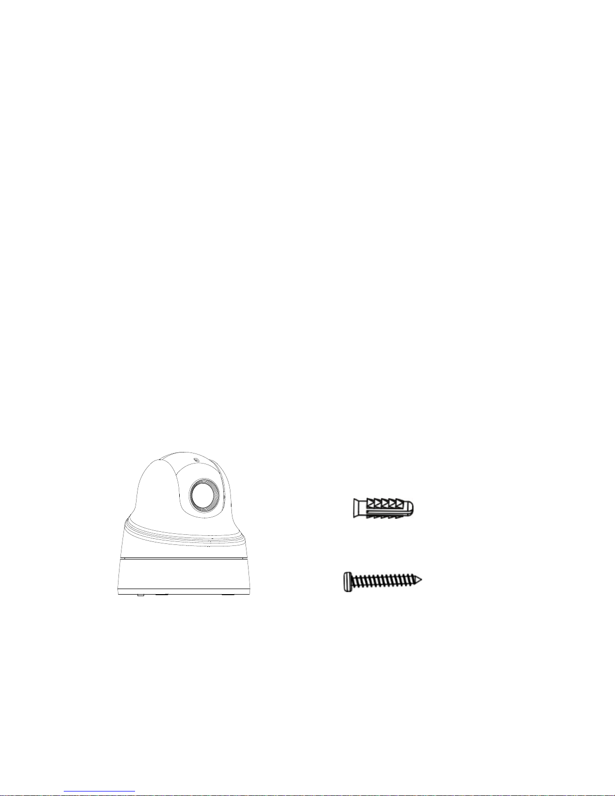
TVP-5101 indoor IR PTZ camera
• Camera
• Screws:
Drywall anchor
7.5 × 24.5 mm (3 pcs)
Screw
PA4 × 25 mm (3 pcs)
Page 9

Installation Guide 5
• Water joint: Provides
water resistance to
network cable
connector.
• Drill template
• Installation guide
• CD with Configuration
manual and TruVision
Device Manager
• Equipment Disposal
sheet
• Battery Disposal sheet
Page 10
6 Installation Guide
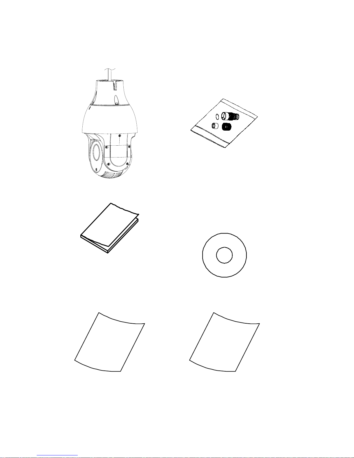
TVP-5102 IR PTZ camera
• Camera
• Water joint: Provides
water resistance to
network cable
connector.
• Installation guide
• CD with
Configuration manual
and TruVision Device
Manager
• Equipment Disposal
sheet
• Battery Disposal
sheet
Page 11
Installation Guide 7
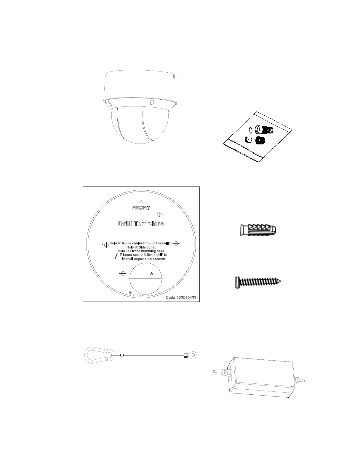
TVP-5103 outdoor IR PTZ camera
• Camera
• Water joint:
Provides water
resistance to
network cable
connector.
• Drill template
• Screws:
Drywall anchor
7.5 × 24.5 mm (4
pcs)
Screw
PA4 × 25 mm (4
pcs)
• Safety lanyard and
mounting screw
• 12 VDC power
supply. Power cord
not included
Page 12
8 Installation Guide
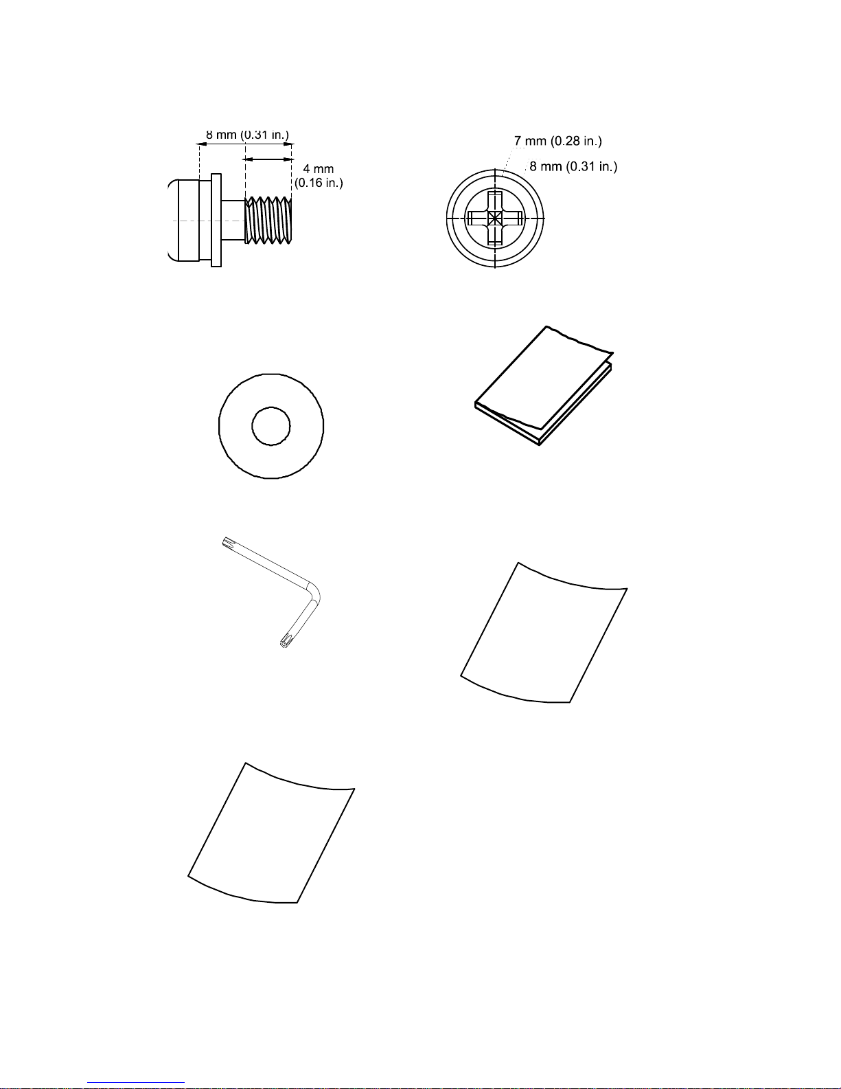
• Safety lanyard screw
• CD with Configuration
manual and TruVision
Device Manager
• Installation guide
• Torx wrench
• Equipment
Disposal sheet
• Battery Disposal sheet
Page 13
Installation Guide 9
CAUTION: Use direct plug-in UL listed power supplies
marked Class 2/CE certified or LPS (limited power source) of
the required output rating as listed on the unit.
CAUTION: Risk of explosion if the battery is replaced by an
incorrect type. Dispose of used batteries according to the
instructions.
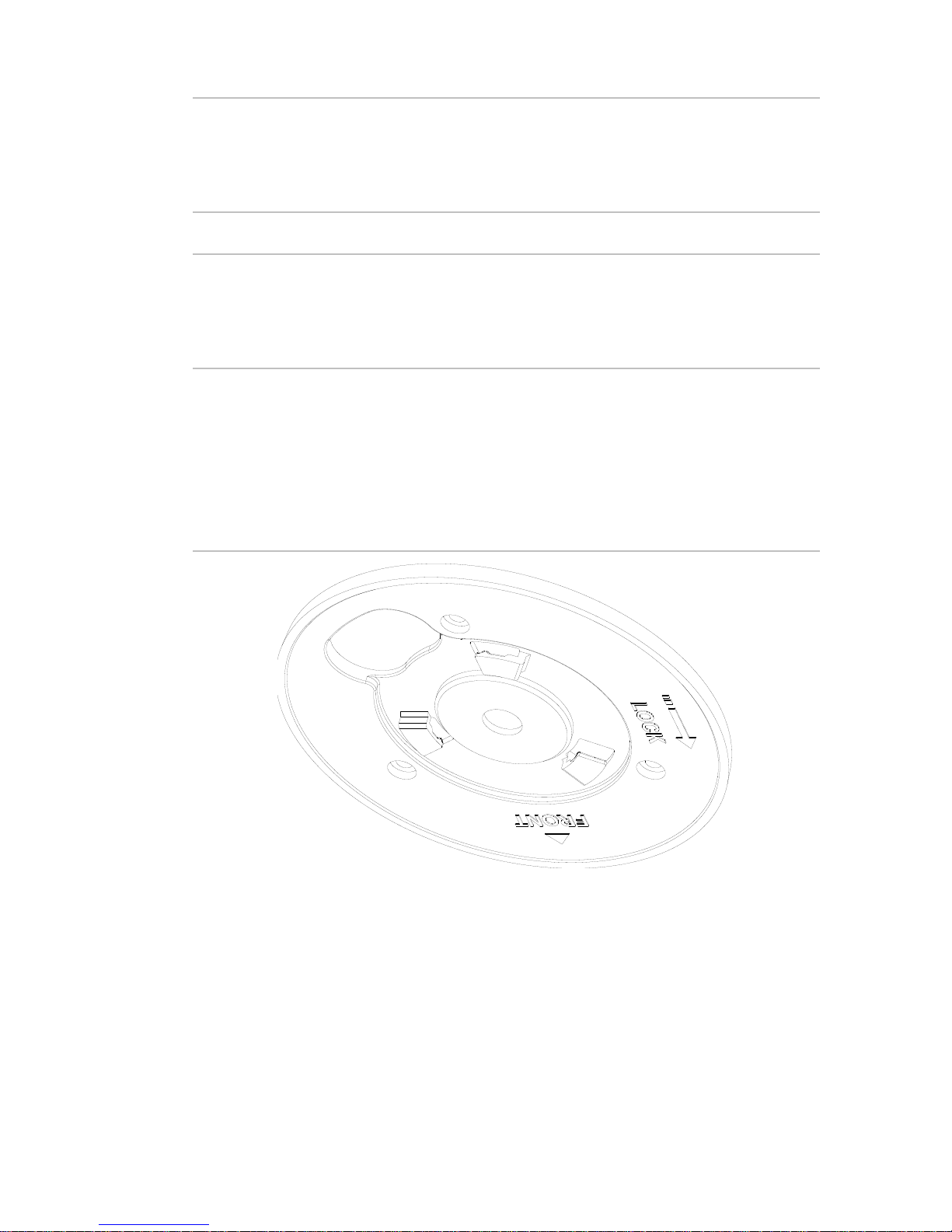
Camera description
Figure 1: TVP-5101 indoor IR PTZ camera adapter plate
Page 14
10 Installation Guide
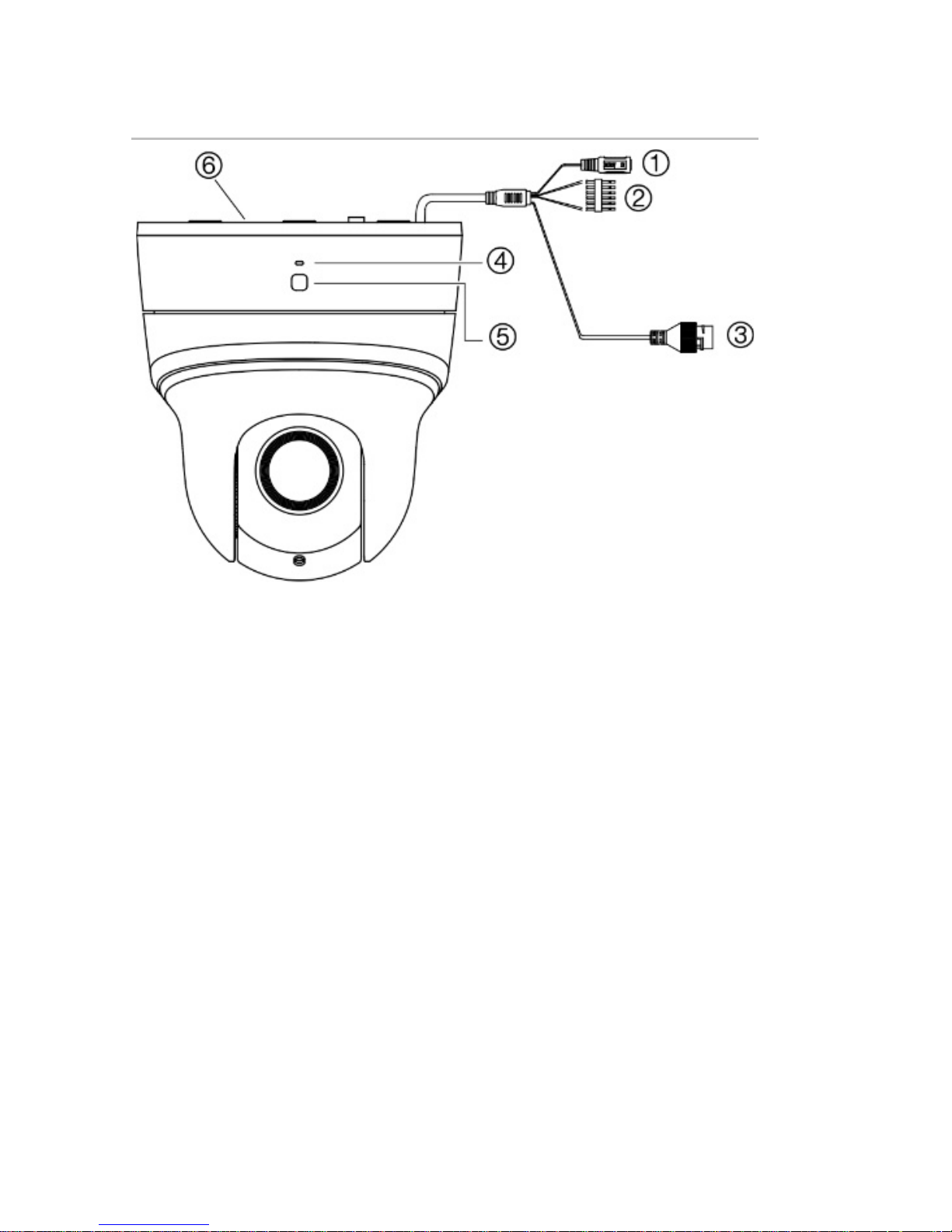
Figure 2: TVP-5101 indoor IR PTZ camera
1. 12 VDC power
2. 1 alarm input (Yellow/Red)
/ 1 alarm output
(Yellow/Green)/ audio
input/output port (Pink)
3. Ethernet RJ45 connector
4. MIC
5. Power LED
6. Adapter plate
Page 15
Installation Guide 11
Plastic access panel area
SD card slot
Dual function: Reset button and
WPS button (not used)
Note: To reset the camera to default settings, press and hold
the Reset button for 10 s and power on or reboot the camera.
You can then restore the default settings, including the user
name, password, IP address, port number., etc.
Page 16
12 Installation Guide
Figure 3: TVP-5102 IR PTZ camera
RED AC24V
YELLOW/GREEN
BLACK AC24V
YELLOW R485 -
ORANGE R485 +
VIEOD
①
②
③
⑤
④
⑥
1. Ethernet RJ45 connector
2. Audio input (Pink)/ output
(Purple) port
3. 2 alarm inputs
(Yellow/Blue,
Yellow/Orange) / 1 alarm
output (White/Red)
4. RS-485 port
5. 960H analog output
6. 24 VAC power
Page 17

Installation Guide 13
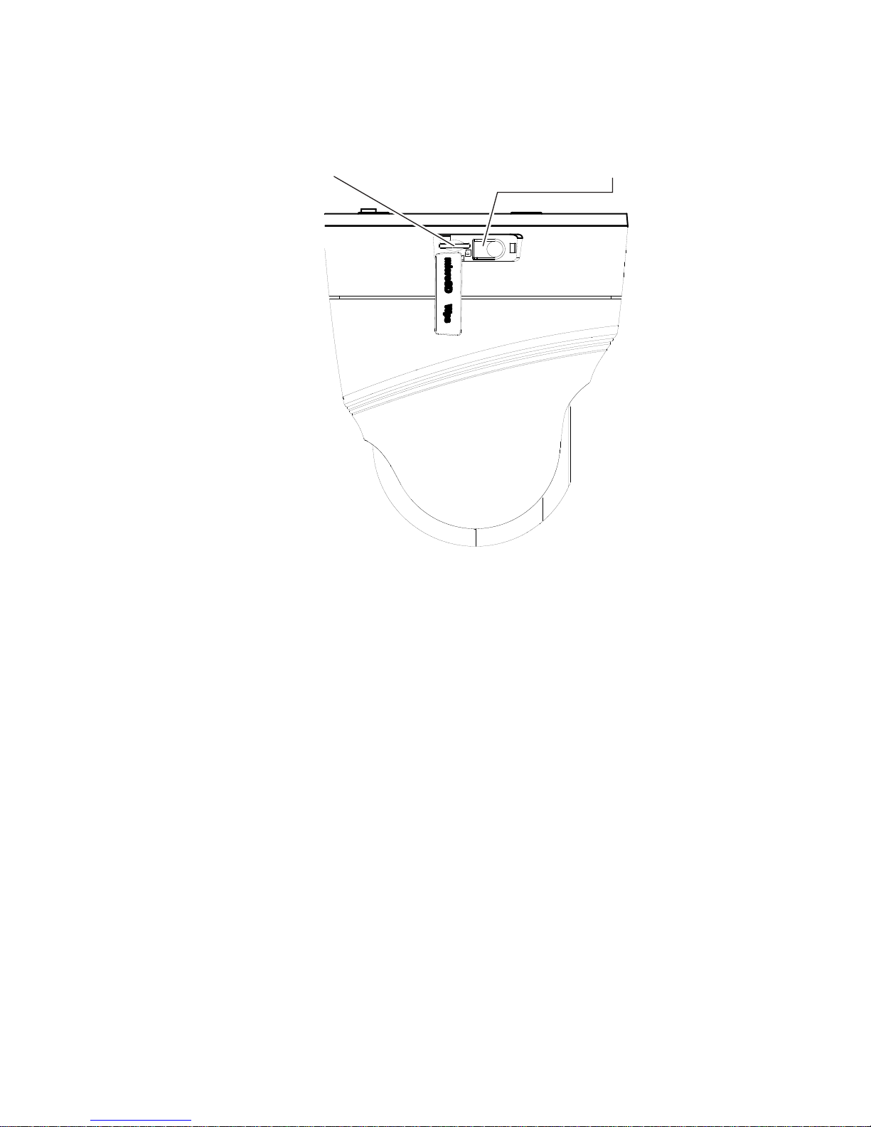
Figure 4: TVP-5102 IR PTZ camera – Accessing the reset
button and SC card slot
Remove the two Phillips
screws
SD card slot
Reset button
Note: To reset the camera to default settings, press and hold
the Reset button for 10 s and power on or reboot the camera.
You can then restore the default settings, including the user
name, password, IP address, port number., etc.
Page 18

14 Installation Guide
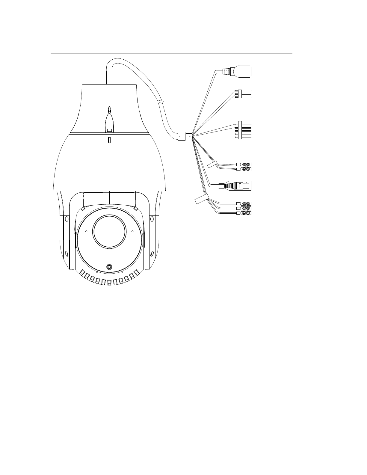
Figure 5: TVP-5103 IR PTZ camera
1. Audio input/output port
2. 12 VDC power supply.
Power cord not included
3. Ethernet RJ45 connector
4. 2 alarm inputs
5. 2 alarm outputs
6. Ground (yellow/green)
Page 19

Installation Guide 15
Figure 6: TVP-5103 IR PTZ camera – Location of the reset
button
Reset button
Note: To reset the camera to default settings, press and hold
the Reset button for 10 s and power on or reboot the camera.
You can then restore the default settings, including the user
name, password, IP address, port number., etc.
IR illuminators
The IR PTZ camera’s built-in IR illumination provides highquality video in low-light environments, even when there is no
other illumination available.
You can configure the IR illumination using the web browser or
a recorder such as a NVR and DVR. If the function is enabled,
the IR light is ON when the camera enters night (black and
white) mode. If disabled, the IR light is always OFF.
The visible IR range may vary due to multiple factors such as
weather, IR reflection level of objects in the frame, lens
Page 20

16 Installation Guide
adjustment, and camera settings. Please refer to the camera
datasheet for the standard IR range.
Note: Avoid installing the IR camera in close proximity to a
solid object, such as a tree or wall. The reflection will cause
over-exposure and loss of detail in the field of view.
Alarm input and output connections
The alarm output can be used to turn on and off an external
alarm device. Connect a 30 VDC/1A external power supply to
the alarm output. If using an AC power supply, an external
relay must be used to prevent electric shock and damage to
the device. See Figure 3 below.
Figure 7
: External alarm output
Page 21

Installation Guide 17
Mounting the TVP-5101 PTZ camera
Note: Make sure that the wall is strong enough to withstand
more than eight times the weight of the PTZ camera and its
accessories.
The PTZ was not designed to be mounted flat to a wall. It
should be mounted to a ceiling. If mounted to a wall, the wall
mount should be used. The lens assembly should be pointing
towards the ground.
To mount the TVP-5101 PTZ camera on the wall (wall
mount is not included with the camera):
1. Remove the wall mount mounting plate from the mount
by loosening the screw that locks the mount in place,
located towards the back of the wall mount. Pull the
mounting plate away from the mount. It is held in place by
two metal clips and dimples.
2. Rotate the PTZ adapter plate counterclockwise to
separate it from the PTZ camera.
Page 22

18 Installation Guide
Open
View of the adapter plate when
mounted to the PTZ
View of the adapter plate that
goes towards the PTZ
3. Align the cable access hole on the adapter plate with the
access hole in the wall mount. Install the adapter plate to
the wall mount using screw B. Keep in mind that the PTZ
pan range is 350 degrees.
4. Route the PTZ cable harness through the cable access
hole.
Page 23

Installation Guide 19
5. Align the PTZ camera with the adapter plate. Rotate the
PTZ clockwise to secure the camera to the adapter plate.
The three clips on the adapter plate lock the camera into
place.
Open
Lock
6. Using the supplied drill template or wall mount mounting
plate, mark and drill four holes in the mounting surface.
Provide access for the interconnect cables.
7. Making sure that the up arrow on the mounting plate is
pointing up, secure the wall mount mounting plate to the
wall with screw A (supplied with the wall mount).
Page 24

20 Installation Guide
8. Connect the corresponding cables.
9. Install the camera assemnbly to the mounting plate by
lining up the two slots in the top of the wall mount with the
two metal clips at the top of the mounting plate. Push
down on the wall mount/PTZ until it snaps into place.
Tighten the screw at the base of the wall mount to lock it
in place.
Page 25

Installation Guide 21
To mount the TVP-5101 PTZ camera on the ceiling:
Note: Make sure the ceiling is strong enough to withstand
more than four times the weight of the PTZ camera and its
accessories.
The PTZ was not designed to be mounted flat to a wall. It
should be mounted to a ceiling. If mounted to a wall, the wall
mount should be used. The lens assembly should be pointing
towards the ground.
1. Rotate the adapter plate counterclockwise to separate it
from the PTZ camera.
Open
View of the adapter plate when
mounted to the PTZ
View of the adapter plate that
goes towards the PTZ
2. A drill template is provided. Drill three holes in the
mounting surface, and provide an access hole for the
interconnect cables. Make sure the front arrow on the
template (or adapter plate) points to the area to be
viewed. Keep in mind that the PTZ pan range is 350
degrees.
Page 26

22 Installation Guide
22.48
均布
?
83.5
3
-?4
.5
?
30
29.3
3. Remove the cable slot cover (as shown) if you want to
route the cable harness along the surface of the ceiling.
Page 27

Installation Guide 23
4. Attach the adapter plate to the ceiling and secure it with
the three supplied screws. Make sure that the front
arrows on the drill template and adapter plate are
aligned.
5. Route the cables.
6. Align the PTZ camera with the adapter plate. Rotate the
PTZ camera clockwise to secure the PTZ to the adapter
plate. There are three clips on the adapter plate that lock
on the camera into place.
Page 28

24 Installation Guide
Open
Lock
Mounting the TVP-5102 PTZ camera
Note: Make sure that the wall is strong enough to withstand
more than eight times the weight of the PTZ camera and its
accessories.
To wall mount the TVP-5102:
1. Refer to the Wall Mount Installation Guide for details.
Attach the wall mount TVP-WMB (not included with the
PTZ) to the wall by aligning the four screw holes of the
mount with expansion anchors.
Page 29

Installation Guide 25
2. Clip the safety lanyard from the wall mount to the metal
loop at the top of the PTZ, as shown.
Page 30

26 Installation Guide
3. Install the PTZ camera to the wall mount, and secure the
PTZ camera using the screws enclosed with the mount.
Page 31

Installation Guide 27
To corner mount the TVP-5102:
1. Refer to the Wall Mount and Corner Mount Adapter
Installation Guide for details. Mark the surface and drill
four mounting holes on the surface. Route the
interconnect cables prior to mounting the corner adapter.
Install the PTZ corner mount adapter to the corner of a
building using the four expansion anchors.
Page 32

28 Installation Guide
2. Install the PTZ wall mount on the corner mount adapter
with four screws.
3. Clip the safety lanyard from the wall mount to the metal
loop at the top of the PTZ, as shown.
Page 33

Installation Guide 29
4. Install the PTZ camera to the wall mount. Secure the PTZ
using the screws enclosed with the wall mount.
To pole mount the TVP-5102:
1. Route the interconnect cables prior to installing the pole
mount adapter. Attach the PTZ pole mount adapter to the
pole using the three hose clamps.
2. Install the PTZ wall mount on the PTZ pole mount
adapter with four screws.
Page 34

30 Installation Guide
3. Clip the safety lanyard from the wall mount to the metal
loop at the top of the PTZ, as shown.
Page 35

Installation Guide 31
4. Install the PTZ camera to the mount. Secure the PTZ
camera using the screws enclosed with the wall mount.
Mounting the TVP-5103 PTZ camera
Note: Make sure that the wall is strong enough to withstand
more than eight times the weight of the PTZ camera and its
accessories.
The PTZ was not designed to be mounted flat to a wall. It
should be mounted to a ceiling. If mounted to a wall, the wall
mount should be used. The bubble assembly should be
pointing towards the ground.
To wall mount the TVP-5103 PTZ (mount not included with
the PTZ):
1. Using the supplied Torx wrench, loosen the locking screw
at the base of the PTZ. Loosen slightly the three screws/
standoffs on the base of the PTZ camera and rotate the
metal adapter plate counterclockwise to separate it from
the PTZ camera.
Page 36

32 Installation Guide
2. Place the metal PTZ adapter plate on the cup base wall
mount. The arrow that states FRONT should be pointing
away from the base of the wall mount. Using screw A,
secure the adapter plate to the wall mount.
Tighten screw A fully. Otherwise, the dome will not slide
properly into place over the three standoffs. The screw
head will block the rotation.
3. Attach the safety lanyard to the base of the PTZ camera,
as shown.
It is important to make sure that the lug, at the end of the
safety lanyard, is contained within the recessed area of
the PTZ base. Otherwise, it will not allow you to lock the
PTZ to the adapter plate.
Page 37

Installation Guide 33
4. Clip the safety lanyard on the metal tab inside of the cup
base of the wall mount, as shown.
Page 38

34 Installation Guide
5. Route the PTZ cable harness through the wall mount. If
you are not using all the features/cables, you may want to
tuck them behind the PTZ adapter plate to keep them out
of the way so they do not interfere when you install the
PTZ on the wall mount.
6. Align the PTZ camera with the adapter plate. Rotate the
PTZ camera clockwise to lock in place, making sure that
the Torx screw is lined up with the metal tab on the metal
adapter plate.
7. Tighten the Torx screw at the base of the PTZ to lock into
place.
Torx screw
Open
Lock
Page 39

Installation Guide 35
To ceiling mount the TVP-5103:
Ceiling mounting without a back box
The camera can be ceiling mounted to indoor and outdoor
solid ceiling construction. The following are the mandatory
preconditions for ceiling mounting:
The thickness of the ceiling must be between 5 to 40 mm.
Make sure the ceiling is strong enough to withstand more
than four times the weight of the PTZ camera and its
accessories.
1. Loosen slightly the three screws on the base of the PTZ.
Using the supplied Torx wrench, loosen the locking screw
at the base of the PTZ. Loosen slightly the three screws
on the base of the PTZ camera and rotate the metal
adapter plate counterclockwise to separate it from the
PTZ camera.
Page 40

36 Installation Guide
2. Attach the drill template (supplied) to the location where
you want to install the PTZ camera. Make sure the front
arrow points to the mounting area.
3. Drill a cable access hole in the ceiling according to the
circle on the template if you want to route the cables
through the ceiling. Unscrew two screws indicated below
to pull out the cable slot cover if you want to route the
cable on the surface of the ceiling.
Unscrew these
screws
Page 41

Installation Guide 37
4. Attach the adapter plate to the ceiling and secure it with
the four supplied screws. Tighten screw A fully.
Otherwise, the dome will not slide properly into place
over the three standoffs. The screw head will block the
rotation. Make sure that the front arrows on the drill
template and adapter plate are aligned.
5. Align the PTZ camera with the adapter plate. Rotate the
PTZ camera clockwise to secure the PTZ to the adapter
plate.
6. Tighten the Torx screw with the Torx wrench that is
provided with the PTZ.
Page 42

38 Installation Guide
Torx
screw
Open
Lock
In-ceiling mounting
Notes:
There must be at least 250 mm of height for in-ceiling
mounting.
The thickness of the ceiling must be between 5 to 40 mm.
Make sure the ceiling is strong enough to withstand more
than four times the weight of the PTZ camera and its
accessories.
1. Using the supplied Torx wrench, loosen the locking screw
at the base of the PTZ. Loosen slightly the three screws
Page 43

Installation Guide 39
on the base of the PTZ camera and rotate the metal
adapter plate counterclockwise to separate it from the
PTZ camera.
2. Cut a hole in the mounting surface using the supplied
template.
?212
Page 44

40 Installation Guide
3. Align the cable access hole in the mounting plate with
cable access in the flush mount. Install the mounting
plate to the flush mount with the A screw. Tighten screw
A fully. Otherwise, the dome will not slide properly into
place over the three standoffs. The screw head will block
the rotation.
4. Route the cables through the flush mount.
5. Align the PTZ camera with the adapter plate. Rotate the
PTZ camera clockwise to secure the PTZ to the adapter
plate. There are three clips on the adapter plate that lock
on the camera into place. Make sure that the locking Torx
screw is lined up with the metal adapter plate.
6. Tighten the Torx screw with the Torx wrench that is
provided with the PTZ.
Page 45

Installation Guide 41
Torx screw
Open
Lock
7. Remove the plastic decorative trim ring from the flush
mount. It is held into place with six small magnets. Insert
the camera assembly and flush mount into the mounting
surface. While holding the camera and mount in place,
use a Phillips screwdriver to lock the camera in place.
(two locations, see the image of the hooks in the
Dimensions section of the TCP-CFM installation
instructions.)
8. Install the trim ring on to the flush mount. The trim ring
will snap into location, locking it in place.
Page 46

42 Installation Guide
Using the camera with an Interlogix NVR
or Hybrid DVR or another system
Please refer to the NVR/DVR user manuals for instructions on
connecting and operating the camera with these systems.
Using the camera with a TruVision
Navigator
A camera must be connected to an Interlogix NVR or hybrid
DVR to be operated by TruVision Navigator. Please refer to
the TruVision Navigator user manual for instructions on
operating the camera with the TruVision Navigator.
Accessing the camera over the internet
Use the web browser to access and control the camera over
the internet.
Note: Any changes made to the camera’s configuration only
apply to this camera.
Page 47

Installation Guide 43
Change the administrator password once the set-up is
complete. Only authorized users should be able to modify
camera settings.
To access the camera online:
1. In the web browser enter the camera’s IP address
(default is 192.168.1.70). The Login dialog box appears.
2. Enter your user name and password.
Default user name: admin
A valid password range must be between 8 and 16
characters. You can use a combination of numbers,
lower and upper case letters, and special characters : _
- , . * & @ / $ ? Space. The password must contain
characters from at least two of these groups. We also
recommend that you reset your password regularly. For
high security systems, it is particularly recommended to
reset the password monthly or weekly for better
protection.
Click Login. The web browser screen appears in live
mode.
3. Click the Configuration tab on the top of the screen
and select the parameter to change.
Page 48

44 Installation Guide
Specifications
TruVision TVP-5101 indoor IR IP PTZ
camera
Electrical
Voltage input
12 VDC, PoE (802.3af)
Power consumption
Max. 9 W
Miscellaneous
Connectors
12 VDC, Audio, Alarm In/Out,
Ethernet RJ45 connector
Operating temperature
-10 to +50 °C (-14 to +122°F)
Dimensions
125 × 136.7 mm
(4.92 × 5.38 in.)
Weight
0.65 kg (1.40 Ib.)
Environmental rating
NA
TruVision TVP-5102 IR IP PTZ camera
Electrical
Voltage input
24 VAC, Hi-PoE
Power consumption
Max. 32 W
Miscellaneous
Connectors
24 VAC, Alarm In/Out, RS-485,
Ethernet RJ45 connector, Audio
in/out (960H) analog output
Operating temperature
-30 to +65 °C (-22 to +149°F)
Page 49

Installation Guide 45
Dimensions
185 × 330 mm
(7.28 × 2.99 in.)
Weight
4 kg (8.82 Ib.)
Environmental rating
IP66
TruVision TVP-5103 IR IP PTZ camera
Electrical
Voltage input
12 VDC, PoE+ (802.3at)
Power consumption
Max. 18 W
Miscellaneous
Connectors
12 VDC, Alarm In/Out, Ethernet
RJ45 connector, Audio in/out
Operating temperature
-30 to +65 °C (-22 to 149°F)
Dimensions
169 × 161 mm
(6.65 × 6.34 in.)
Weight
2.45 kg (5.40 Ib.)
Environmental rating
IP66
Page 50

46 Installation Guide
Pin definitions
There are eight wires on a standard UTP/STP cable and each
wire is color-coded. The following shows the pin allocation and
color of straight and crossover cable connection:
Figure 8: Straight-through cable
1 White/Orange
White/Orange 1
2 Orange Orange 2
3 White-Green White-Green 3
4 Blue Blue 4
5 White/Blue White/Blue 5
6 Green Green 6
7 White/Brown White/Brown 7
8 Brown Brown 8
Figure 9: Cross-over cable
1 White/Orange
White/Orange 1
2 Orange Orange 2
3 White-Green White-Green 3
4 Blue Blue 4
5 White/Blue White/Blue 5
6 Green Green 6
7 White/Brown White/Brown 7
8 Brown Brown 8
Page 51

Installation Guide 47
Please make sure your connected cables have the same pin
assignment and color as above before deploying the cables in
your network.
Page 52

 Loading...