

Page 1
P/N 1073419-EN • REV A • ISS 13FEB18 1 / 4
TVD-CB3 Cup Base Installation
Instructions
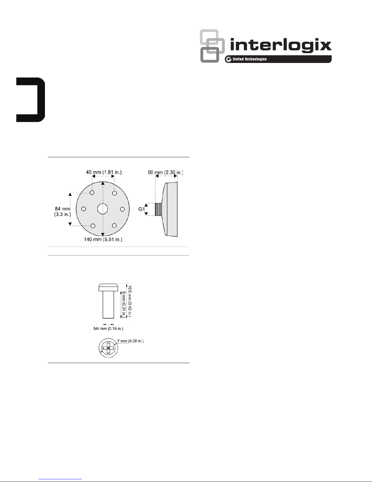
Dimensions
Dimensions:
Weight: 335 g (0.73 lb.)
Accessories:
Screw A: 3 pcs.
Used to install the camera adapter plate to the cup base.
Supported devices
• TVD-5301
• TVD-5302
• TVD-5303
• TVT-5501
• TVT-5502
• TVD-2202/4202
• TVD-5304
• TVD-5305
• TVD-5306
• TVT-5301
• TVT-5302
• TVT-5303
• TVT-5304
• TVT-5305
• TVT-5306
• TVT-5307
• TVD-5401
• TVD-5402
• TVD-5403
• TVD-5501
• TVD-5502
• TVD-2401/4401
• TVD-2402/4402
• TVD-2403/4403
• TVD-2404/4404
• TVD-2405/4405
• TVD-2406/4406
• TVT-2401/4401
• TVT-2402/4402
• TVT-2403/4403
• TVT-2404/4404
• TVD-SNB Swan
Neck Wall Mount
• TVD-PPB
Pendant Mount
• TVD-CBW Wall
Mount
Installing a TVD-CB3 cup base
to a dome camera
It is a similar process for a turret camera.
Refer to the turret camera installation guide
for details. When assembling a TVD-CB3 to a
dome camera, you require:
• TVD-CB3 cup base
• Adapter plate, included with dome or
turret camera
Page 2
2 / 4 P/N 1073419-EN • REV A • ISS 13FEB18
• Adapter plate mounting screws
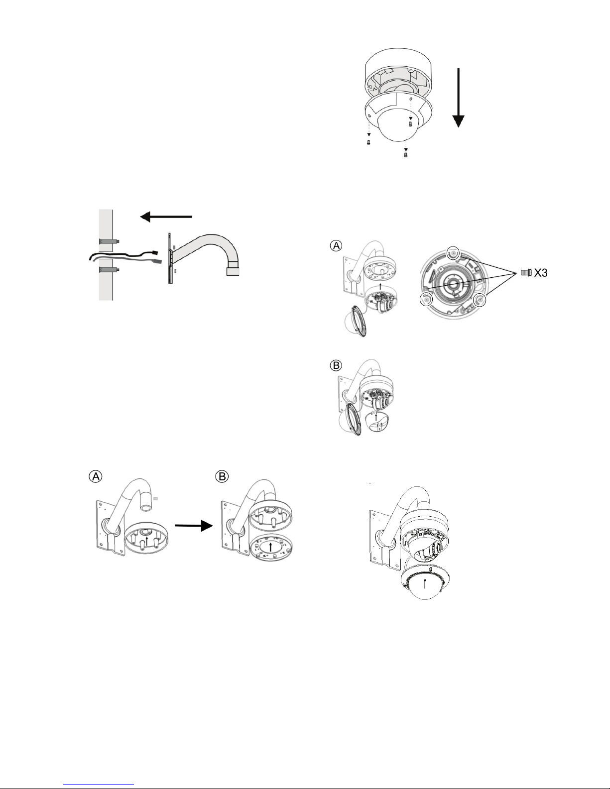
To mount a dome camera to a TVDSNB wall mount with a TVD-CB3 cup
base:
1. Pull the camera cables through the wall
mount. Attach the swan neck mount to
the wall using the expansion anchors
that are provided with the swan neck
mount.
2. Screw the cup base onto the swan neck
mount and tighten with the locking
screw, as shown below (A). Then attach
the camera adapter plate to the cup base
(B) using screw A.
Note: The mounting plate is shipped with
the camera. The image below may not
match the actual plate supplied. The
included plate varies depending on the
camera.
3. Loosen the screws on the bubble
assembly using the Torx wrench that is
supplied with the camera. Remove the
bubble assembly and liner from the
dome module.
4. Connect the cables to the dome camera.
5. Attach the dome assembly of the camera
(A) to the camera adapter plate. Then reattach the dome liner (B) using screw A.
6. Re-attach the bubble assembly to the
camera.
To mount a dome camera to a TVDPPB pendant bracket with a TVD-CB3
cup base:
It is a similar process for a turret camera.
Refer to the turret camera installation guide
for details.
Page 3

P/N 1073419-EN • REV A • ISS 13FEB18
3 / 4
1. Screw the pendant mounting plate onto
the pendant mount tube and tighten with
the locking screw, as shown.
2. Pull the camera interconnect cables
through the pendant mount. Attach the
mount to the ceiling using the expansion
anchors that are included with the
pendant mount.
3. Screw the cup base onto the pendant
mount and tighten with the locking screw.
Using the adapter plate mounting screws,
attach the camera mounting plate to the
cup base.
Note: The camera mounting plate is
shipped with the dome camera. The
image below may not match the actual
plate supplied. The included plate varies
depending on the camera.
4. Loosen the screws on the dome
assembly (1) using the using the Torx
wrench that is supplied with the camera,
and remove the dome bubble assembly
and liner (2).
5. Connect the cables to the dome camera.
6. Using screws that are supplied with the
camera, attach the dome assembly to
the mounting plate.
7. Re-attach the dome liner and bubble
assembly to the camera.
Page 4

4 / 4 P/N 1073419-EN • REV A • ISS 13FEB18
Legal and regulatory
information
Copyright
© 2018 United Technologies Corporation. All
rights reserved.
Interlogix is part of UTC Climate, Controls &
Security, a unit of United Technologies
Corporation.
Trademarks and
patents
The trade names used in this document may
be trademarks or registered trademarks of
the manufacturers or vendors of the
respective products.
Manufacturer
Interlogix.
2955 Red Hill Avenue, Costa Mesa, CA
92626 5923, USA
Authorized EU manufacturing representative:
UTC Fire & Security B.V.
Kelvinstraat 7, 6003 DH Weert, The
Netherlands
Certification
Product warnings
and disclaimers
THESE PRODUCTS ARE INTENDED FOR
SALE TO, AND INSTALLATION BY, AN
EXPERIENCED SECURITY
PROFESSIONAL. UTC FIRE & SECURITY
CANNOT PROVIDE ANY ASSURANCE
THAT ANY PERSON OR ENTITY BUYING
ITS PRODUCTS, INCLUDING ANY
“AUTHORIZED DEALER”, IS PROPERLY
TRAINED OR EXPERIENCED TO
CORRECTLY INSTALL SECURITY
RELATED PRODUCTS.
For more information on warranty
disclaimers and product safety information,
please check
www.firesecurityproducts.com/policy/product
-warning/ or scan the following code:
Contact information
and manuals
For contact information go to:
www.interlogix.com or
www.firesecurityproducts.com
To get translations
for this and other product
manuals go to:
www.firesecurityproducts.com
 Loading...