


IFS MC352-4P-2S User
Manual
P/N 1072702 • REV A • ISS 22OCT13

Copyright © 2013 United Technologies Corporation
r
Interlogix is part of UTC Climate Controls & Security, a unit of United
Technologies Corporation. All rights reserved.
Trademarks and
patents
Manufacture
Intended use
Certification
FCC compliance
The IFS MC352-4P-2S name and logo are trademarks of United
Technologies.
Other trade names used in this document may be trademarks or
registered trademarks of the manufacturers or vendors of the
respective products.
Interlogix
3211 Progress Drive, Lincolnton, NC 28092 USA
Authorized EU manufacturing representative:
UTC Climate Controls & Security B.V.,
Kelvinstraat 7, 6003 DH Weert, Netherlands
Use this product only for the purpose it was designed for; refer to the
data sheet and user documentation for details. For the latest product
information, contact your local supplier or visit us online at
www.interlogix.com.
N4131
This equipment has been tested and found to comply with the limits
for a Class A digital device, pursuant to part 15 of the FCC Rules.
These limits are designed to provide reasonable protection against
harmful interference when the equipment is operated in a commercial
environment. This equipment generates, uses, and can radiate radio
frequency energy and, if not installed and used in accordance with
the instruction manual, may cause harmful interference to radio
communications.
You are cautioned that any changes or modifications not expressly
approved by the party responsible for compliance could void the
user's authority to operate the equipment.
ACMA compliance
Notice! This is a Class A product. In a domestic environment this
product may cause radio interference in which case the user may be
required to take adequate measures.
Canada
This Class A digital apparatus complies with Canadian ICES-003.
Cet appareil numérique de la classe A est conforme á la norme
NMB-003du Canada.
European Union
directives
2004/108/EC (EMC Directive): Hereby, UTC Climate Controls &
Security Corporation, Inc. declares that this device is in compliance
with the essential requirements and other relevant provisions of
Directive 2004/108/EC.
Contact Information For contact information, see www.interlogix.com
www.utcfssecurityproducts.eu
- 2 -
.
or

INTRODUCTION 4
1.
1.1 PACKAGE CONTENTS ..........................................................................................................................4
1.2 HOW TO USE THIS MANUAL ................................................................................................................. 4
1.3 PRODUCT FEATURES ..........................................................................................................................5
1.4 PRODUCT SPECIFICATIONS..................................................................................................................6
1.5 PHYSICAL DIMENSIONS .......................................................................................................................7
TABLE OF CONTENTS
2. INSTALLATION 9
2.1 PRODUCT DESCRIPTION ......................................................................................................................9
2.1.2 Switch Front Panel.................................................................................................................. 10
2.1.3 LED Indicators ........................................................................................................................11
2.1.4 Switch Upper Panel ................................................................................................................12
2.1.5 Wiring the Power Inputs..........................................................................................................13
2.1.6 Wiring the Fault Alarm Contact ...............................................................................................14
2.1.7 Cabling....................................................................................................................................15
2.1.7.1 Installing the SFP transceiver ..............................................................................................15
2.1.7 Redundancy Overview............................................................................................................ 19
2.2 MOUNTING INSTALLATION .................................................................................................................. 20
2.2.1 DIN-Rail mounting...................................................................................................................20
2.2.2 Wall Mount Plate Mounting ..................................................................................................... 22
3. APPLICAITON 23
4. SWITCH OPERATION 25
4.1 ADDRESS TABLE .............................................................................................................................. 25
4.2 LEARNING ........................................................................................................................................25
4.3 FORWARDING & FILTERING................................................................................................................ 25
4.4 STORE-AND-FORWARD .....................................................................................................................25
4.5 AUTO-NEGOTIATION .........................................................................................................................26
5. TROUBLESHOOTING 27
6. CABLE CONNECTION PARAMETERS 28
APPENDIX A: NETWORKING CONNECTION 29
A.1 SWITCH’S RJ-45 PIN ASSIGNMENTS ..................................................................................................29
A.2 RJ-45 CABLE PIN ASSIGNMENTS .......................................................................................................30
- 3 -

1. Introduction
Thank you for purchasing IFS Layer 2 Industrial Gigabit Switch with 4-Port 802.3at PoE+, The
MC352-4P-2S descriptions of these models are as follows:
MC352-4P-2S : Industrial 4-Port 10/100/1000T 802.3at PoE + 2-Port 100/1000X SFP Ethernet
Switch (-40~75 Degree C)
In the following section, the term “Industrial Gigabit PoE+ Switch” means the MC352-4P-2S.
1.1 Package Contents
Open the box of the Industrial Gigabit PoE+ Switch and carefully unpack it. The box should contain the
following items:
● Industrial Gigabit PoE+ Switch x 1
● User's Manual x 1
● DIN Rail Kit x 1
● Wall Mount Kit x 1
If any of these are missing or damaged, please contact your dealer immediately; if possible, retain the
carton including the original packing material, and use them again to repack the product in case there is a
need to return it to us for repair.
1.2 How to Use This Manual
This Industrial Gigabit PoE+ Switch User Manual is structured as follows:
Chapter 2 Installation
The chapter explains the feature, functionality and the physical installation of the Industrial Gigabit
PoE+ Switch.
Chapter 3 Application
The chapter explains the Industrial Gigabit PoE+ Switch application.
Chapter 4 Switch operation
The chapter explains the Industrial Gigabit PoE+ Switch transmit operation.
Chapter 5 Troubleshooting
The chapter explains the troubleshooting of the Industrial Gigabit PoE+ Switch.
Chapter 6 Cable Connection Parameters
The chapter contains the cable connection parameters of the Industrial Gigabit PoE+ Switch.
Appendix A
This chapter contains cable information of the Industrial Gigabit PoE+ Switch.
- 4 -

1.3 Product Features
Physical Port
MC352-4P-2S 4-Port 10/100/1000Base-T RJ-45 with IEEE 802.3af/802.3at PoE+ Injector
2 SFP interfaces, 100/1000Base-X dual mode (DIP switch control)
Power over Ethernet
Complies with IEEE 802.3af/IEEE 802.3at Power over Ethernet Plus End-Span PSE
Up to 4 IEEE 802.3af/802.3at devices powered
Supports PoE Power up to 30.8 watts for each PoE ports
Provides DC 52V power over RJ-45 Ethernet cable to PD with Ethernet port
Auto-detection of IEEE 802.3af/at equipment and protects devices from being damaged by
incorrect installation
Remote power feeding up to 100m
Layer 2 Features
Supports Auto-negotiation and 10/100Mbps half/full duplex and 1000Mbps full duplex mode
Prevents packet loss with back pressure (Half-Duplex) and IEEE 802.3x PAUSE frame flow
control (Full-Duplex)
Automatic address learning and address aging
Industrial Case/Installation
IP30 aluminum metal case protection
DIN Rail and Wall Mount Design
48V DC redundant power with polarity reverse protect function and connective removable
terminal block for master and slave power
Supports EFT protection 6000 VDC for power line
Supports 6000 VDC Ethernet ESD protection
-40 to 75 Degree C operating temperature
Fiber Port Redundancy
Dual SFP Ports Auto Link Redundant Mode Support
Link status auto-detect and redundant on Dual ports with same connector type
Only Primary-Port is active at a time, the Backup-Port is blocked
While Primary-Port link fail occurrences, the traffic swaps to Backup-Port automatically
Once the Primary-Port status backs to link up, the traffic swaps from Backup-Port to
Primary-Port
- 5 -

1.4 Product Specifications
Model MC352-4P-2S
Hardware Specification
Copper Ports
SFP / mini-GBIC Slots
DIP Switch
Connector
Alarm
LED
ESD Protection 6KV DC
4 x 10/100/1000Base-T RJ-45 TP
Auto-MDI/MDI-X, Auto-negotiation
2 x SFP interfaces support 1000Base-SX/LX and 100Base-FX SFP transceivers
DIP-1: SFP Port 5 1000Base-X (default) / 100Base-FX
DIP-2: SFP Port 6 1000Base-X (default) / 100Base-FX
DIP-3 : Switch (default) / Fiber Redundant mode
Terminal Block
Pin 1 & 2 for Power 1; Pin 3 & 4 for alarm; Pin 5 & 6 for Power 2
Provides one relay output for power fail
Alarm Relay current carry ability: 1A @ DC 24V
3x LED for System and Power:
Green: DC Power 1
Green: DC Power 2
Green: Power Fault
2 x LED for Per Copper Port (Port-1~Port-4):
Green: 1000 LNK/ACT, Orange:100 LNK/ACT
Orange: PoE In-use
1 x LED for Per mini-GBIC interface (MC352-4P-2SPort-5 and Port-6):
Green: LNK/ACT
4 x LED for PoE Power Usage (W)
Orange: 30, 60, 90 and 120W
EFT Protection 6KV DC
Enclosure IP30 type metal case
Installation DIN rail kit and wall mount ear
Dimensions (W x D x H) 152 x 107 x 72 mm
Weight
Power Requirement
Power Consumption/
Dissipation
Twisted-Pair 10Base-T: 2-Pair UTP CAT. 3,4,5, up to 100 meter
Cable
Fiber-Optic Cable
1539g
48V DC, 5A max.
Redundant power with polarity reverse protection
135.1 watts / 451 BTU
100Base-TX: 2-Pair UTP CAT. 5, 5e up to 100 meter
1000Base-T: 4-Pair UTP CAT. 5e,6 up to 100 meter
- 6 -

Switch Specification
Switch Processing Scheme Store-and-Forward
Address Table 1K entries
Flow Control
Switch fabric
Throughput
(packet per second)
Maximum Transmit Unit 9216 bytes
Speed
Power over Ethernet
PoE Standard IEEE 802.3af/IEEE 802.3at Power over Ethernet/PSE
PoE Power Supply Type End-Span
PoE Power Output
Power Pin Assignment 1/2(+), 3/6(-)
Back pressure for half duplex
IEEE 802.3x Pause Frame for full duplex
12Gbps
8.93Mpps@64bytes
TP: 10/20Mbps, 100/200Mbps, 2000Mbps
SX/LX: 2000Mbps (Full-duplex)
FX: 200Mbps (Full-duplex)
Per port 52V DC, 275mA. Max. 15.4 watts (IEEE 802.3af)
Per port 52V DC, 535mA. Max. 30 watts (IEEE 802.3at)
Max. number of Class 4 PD 4
Standards Conformance
IEEE 802.3 Ethernet/10Base-T
IEEE 802.3u Fast Ethernet/100Base-TX
IEEE 802.3ab Gigabit Ethernet/1000Base-T
Standards Compliance
Regulation Compliance FCC Part 15 Class A, CE
Stability Testing
Environment
Temperature
Humidity
IEEE 802.3z Gigabit Ethernet/1000Base-SX/LX
IEEE 802.3x Full-Duplex Flow Control
IEEE 802.3at Power over Ethernet Plus
IEEE 802.3af Power over Ethernet
IEC60068-2-32 (Free fall)
IEC60068-2-27 (Shock)
IEC60068-2-6 (Vibration)
Operating: -40~75 Degree C
Storage: -40~75 Degree C
Operating: 5~95% (Non-condensing)
Storage: 5~95% (Non-condensing)
- 7 -
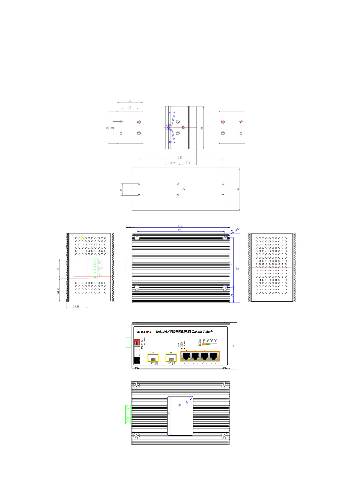
1.5 Physical Dimensions
MC352-4P-2S Industrial Gigabit PoE+ Switch dimensions (W x D x H): 161 x 107 x 72 mm
- 8 -

2. Installation
This section describes the functionalities of the Industrial Gigabit PoE+ Switch’s components and guides
how to install it on the desktop. Basic knowledge of networking is assumed. Please read this chapter
completely before continuing.
2.1 Product Description
High Power PoE for Security and Public Service Applications
To fulfill the demand of High Power PoE for network applications with Gigabit speed transmission under
wide temperature, the MC352-4P-2S provide 4 10/100/1000Mbps ports featuring both IEEE 802.3af and
IEEE 802.3at Power over Ethernet Plus (PoE+) that combine up to 30-watt power output and data per
port over one Cat.5E / 6 Ethernet cable.
With a total of up to 120 watts of PoE output capability, the MC352-4P-2S is designed specifically to
satisfy the growing demand of higher power consuming network PDs (powered devices) such as PTZ
(Pan, Tilt & Zoom) speed dome network cameras, multi-channel (802.11a / b / g / n) wireless LAN access
points and other PoE network devices by providing double PoE power, rather than the current
conventional 802.3af PoE.
Environmentally Hardened Design
The MC352-4P-2S is equipped with rugged IP30 metal case for easy deployment in heavy Industrial
demanding environments. With IP30 metal case protection, the MC352-4P-2S provide a high level of
immunity against electromagnetic interference and heavy electrical surges which are usually found on
plant floors or in curb side traffic control cabinets. Being able to operate in the temperature range from
-40 to 75 Degree C, the MC352-4P-2S can be placed in almost any difficult environment. The
MC352-4P-2S allows either DIN rail or wall mounting for efficient use of cabinet space.
Adjustable 6-Port Switch Mode or 4 + 2 Fiber Redundant Mode
Via the built-in DIP switch, the MC352-4P-2S can be configured as 6-Port Ethernet switch or 4+2 fiber
redundant mode. With the 6-port switch mode, the MC352-4P-2S can operate in Store-and-Forward
mechanism with high performance; on the other hand, when in the 4+2 fiber redundant mode, it provides
rapid fiber redundancy of link for highly critical Ethernet applications. The redundant-mode also supports
auto-recovering function, if the destination port of a packet is link down, it will forward the packet to the
other port of the backup pair.
- 9 -

2.1.1 Switch Front Panel
Figure 2-1 shows the front panels of MC352-4P-2S Industrial Gigabit PoE+ Switches.
Figure 2-1: MC352-4P-2S Front Panels
PoE Power Usage LED
The front panel of the Industrial Gigabit PoE+ Switch has four LEDs which indicate “PoE Power Usages
(W)” of 30W, 60W, 90W and 120W. With these LED indications, you can monitor current PoE power in
use status of Industrial Gigabit PoE+ Switch easily and efficiently.
- 10 -
 Loading...