

Page 1

IFS SFP Transceiver
User Manual
P/N 1069181 • REV 1.0 • ISS 6-AUG-2014
Page 2

Copyright
© 20
14 United Technologies Corporation
Trademarks and
patents
Interlogix is part of UTC Building
Technologies Corporation
The SFP Tranciever name and logo are trademarks of United Technologies.
Other trade names used in this document may be trademarks or registered
trademarks of the manufacturer
Manufacturer
Interlogix
3211 Progress Drive, Lincolnton, NC 28092 USA
Authorized EU manufacturing representative:
UTC Climate Controls & Security B.
Kelvinstraat 7, 6003 DH Weert, Netherlands
Version
This doc
Certification
N4131
FCC compliance
Class B:
for a Class B digital device, pursuant to par
are designed to provide reasonable protection against harmful interference in a
residential installation. This equipment generates, uses, and can radiate radio
frequency energy and, if not installed and us ed in acc or danc
instructions, may cause harmful interference to radio communications.
There is no guarantee that interference will not occur in a particular installation.
If this equipment does cause harmful interference to radio or television
reception, which
user is encouraged to try to correct the interference by one or more of the
following measures:
•
•
•
•
European Union
directives
2004/108/EC (EMC directive)
Inc.
and other relevant provisions of Directive 2004/108/EC
2002/96/EC (WEEE directive):
disposed of as un
recycling, return this product to your local supplier upon the purchase of
equivalent new equipment, or dispose of it at designated collection points. For
more information see: www.recyclethis.info.
Contact information
For contact information, see
www.utcfssecurity
& Industrail Systems, Inc. a United
. All rights reserved
s or vendors of the respective products.
V.,
ument applies to IFS SFP Transceiver version 02.02
This equipment has been tested and found to comply with the limits
t 15 of the FCC Rules. These limits
e with the
can be determined by turning the equipment off and on, the
Reorient or relocate the receiving antenna.
Increase the separation between the equipment and receiver.
Connect the equipment into an outlet on a circuit different from that to
which the receiver is connected.
Consult the dealer or an experienced radio/TV technician for help.
: Hereby, UTC Buildin g & Indus tr ail S ystems,
declares that this device is in compliance with the essential requirements
Products marked with this symbol cannot be
sorted municipal waste in the European Union. For proper
products.eu
www.interlogix.com or
Page 3
o not look directly into a laser aperture, as prolonged exposure
Only trained and qualified personnel should be allowed to install or
Safety Notices
The fiber optic SFP transceiver modules are equipped with a Class 1 laser, which
emits invisible radiation. Read the following safety warnings carefully.
Class 1 Laser Product
Complies with FDA Regulation 21 CFR 1040.10 and 1040.11
Class 1 radiation is present when the device or system is pow ered
up. D
may cause eye damage.
replace these SFP modules
Page 4

Content
Overview 1
Checklist 2
Installing an IFS SFP Module 3
Connecting the fiber cable 3
Removing the SFP transceiver 4
SFP Specifications 5
Appendix A 9
Fiber Optical Cable Connection Parameters 9
IFS SFP Tranceivers User Manual i
Page 5
Overview
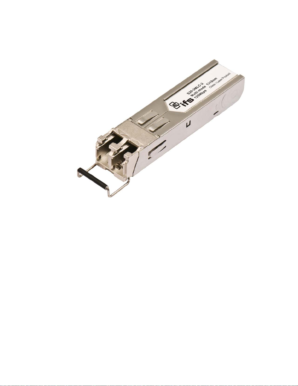
Thank you for purchasing an IFS SFP transceiver. The IFS SFP transceiver can
be installed into any IFS network equipment with a 100Base-FX or 1000BaseSX/LX mini-GBIC interface. This user guide provides an overview of the various
IFS SFPs (also known as mini-GBIC) transc eiver modules availabl e fr om
Interlogix. This user guide also provides instructions for installing, connecting and
removing these transceivers. These SFP transceiver modules are hot-pluggable,
which means you can insert and remove these modules into any IFS network
equipment with a mini-GBIC port without interrupting the host system. The IFS
SFP line also features a selection of environmentally hardened SFPs designed
for operating in environments from -40~75 degrees Celsius.
IFS SFP Tranceivers User Manual 1
Page 6

Checklist
The SFP package should contain the foll owing items:
• The SFP Transceiver Module x1
• This User Manual x1
If any items are missing or damaged, please consult Interlogix or the
dealer/distributor from whom you purchas ed your SFP transceiver module.
2 IFS SFP Tranceivers User Manual
Page 7

Installing an IFS SFP Module
This section describes how to insert an IFS SFP transceiver into a mini-GBIC
slot.
The IFS SFP transceivers are hot-pluggable and hot-swappable. You can insert
and remove an IFS SFP transceiver in any IFS network equipment with a miniGBIC port without having to power down the switch or media converter. As
shown in Figure 1.
Figure 1: Inserting an IFS SFP tranceiver
Install the IFS SFP into an IFS network switch or media converter before
connecting a cable coming from another switch, workstation or media converter.
1. Make sure both pieces of network equipment that you are connecting
together are using the same media t y pe SFP. For example: 100Base-FX to
100Base-FX or 1000Base-SX to 1000Base-SX.
2. Check to make sure that the fiber-optic cable type matches the SFP
transceiver model.
• S20 Series and S25 Series optics operate with multimode OM1, OM2
or OM3 fiber. LC type fiber connectors are required.
• S30 Series and S35 Series optics operate with single mode fiber. LC
type fiber connectors are required.
Connecting the fiber cable
1. Insert the duplex LC connector from the network fiber cable into the SFP
transceiver.
IFS SFP Tranceivers User Manual 3
Page 8
1
2
2. Connect the other end of the cable to a device – i.e. switches with an SFP
installed, fiber NIC on a workstation or a Media Converter.
3. Check the LNK/ACT LED of the SFP slot of the switch / converter. Ensure
that the SFP transceiver is operating correctly.
4. Check the link mode o f the SFP por t to see if there is any link failure. With
some fiber-NICs or Media Converters, setting the link mode to “1000 Force”
or “100 Force” may be needed for proper operation.
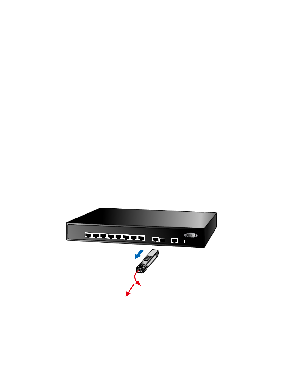
Removing the SFP transceiver
1. Make sure there is no network activity by consulting with a network
administrator before removing the SFP or use the switch or media converters
management interface (if available) to disable the port in advance.
2. Gently remove the fiber optic cable connector.
3. Flip the wire handle of the SFP module out to a horizontal position.
4. Pull out the SFP module gently out of the mini-GIBIC slot with the wire
handle.
Figure 2: Pull out the SFP transceiver
Caution: Never pull out the SFP transceiver module without using the pull
handle or the push bolts on the module. Directly pulling out the SFP module with
force could damage the SFP module and mini-GIBIC slot of the network device.
4 IFS SFP Tranceivers User Manual
Page 9

Twisted Pair SFP
S30
Fast
Ethernet
S20
S25
Fast Ethernet
S20
S25
40 to +75C
)
Fast Ethernet
Wave Length
S20
S25
40 to +75C
40 to 167F)
SFP Specifications
The IFS SFP transceivers are available in the following models.
1000 Base TX GigE
Part # Connector Wire Type Max Distance
-RJ RJ 45 Cat 5e 100M (328 ft)
100 Base FX
Part #
-2MLC2 LC 2 Multimode
-2MLC2 LC 2 Multimode
Part #
-2SLC20 LC 2
-2SLC20 LC 2
Fiber
Connector
100 Base LX
Fiber
Connector
# of
Fibers
# of
Fibers
Fiber Type
Fiber Type
Single
Mode
Single
Mode
Max
Distance
2km
(1.2mi)
2km
(1.2mi)
Max
Distance
20km
(12mi)
20km
(12mi)
Wave
Length
1310nm 12 -20 ~ -14 -32
1310nm 12 -20 ~ -14 -32
Wave
Length
1310nm 19 -15 ~ -8 -34
1310nm 19 -15 ~ -8 -34
Optical
Budget
(dBm)
Optical
Budget
(dBm)
Optical
Power
(dBm)
Optical
Power
(dBm)
Receiver
Sensitivitiy
(dBm)
Receiver
Sensitivitiy
(dBm)
Operating
Temperature
0 to + 50C
(32 to 122F)
-40 to +75C
(-40 to 167F)
Operating
Temperature
0 to + 50C
(32 to 122F)
-
(-40 to 167F
100 Base BX
Part #
-1SLC/A-20 LC 1
-1SLC/B-20 LC 1
IFS SFP Tranceivers User Manual 5
Fiber
Connector
# of
Fibers
Fiber
Type
Single
Mode
Single
Mode
Max
Distance
20km
(12mi)
20km
(12mi)
Optical
TX RX
1310/1550nm 18 -14 ~ -8 -32
1550/1310nm 18 -14 ~ -8 -32
Budget
(dBm)
Optical
Power
(dBm)
Receiver
Sensitivitiy
(dBm)
Operating
Temperature
0 to + 50C
(32 to 122F)
-
(-
Page 10

Gigabit Ethernet
Fiber Type
Max Distance
OM1 Multimode fiber @ 200/500MHz
OM2 Multimode fiber @ 500.500MHZ
Gigabit Ethernet
Fiber Type
Temperature
OM3 Multimode fiber @ 2000/500MHz
Gigabit Ethernet
1000 Base SX
Part #
Fiber
Connector
# of
Fibers
OM1 &
OM2
S30-2MLC LC 2 Multimode
S35-2MLC LC 2 Multimode
-km
-km Laser Rated for GbE LANs
1000 Base SX
Part #
Fiber
Connector
# of
Fibers
OM3
S30-2MLC-2 LC 2 Multimode
-km Optimized got 850nm VCSELs
OM1/OM2
220/550m
(720/1800ft)
220/550m
(720/1800ft)
Max
Distance
OM3
2km
(1.2mi)
Wave
Length
Optical
Budget
(dBm)
Optical
Power
(dBm)
Receiver
Sensitivitiy
(dBm)
850nm 7.5 -9.5 ~ -1 -17
850nm 7.5 -14 ~ -8 -17
Wave
Length
Optical
Budget
(dBm)
Optical
Power (dBm)
Receiver
Sensitivitiy
(dBm)
1310nm 10 -9 ~ -1 -19
Operating
Temperature
0 to + 50C
(32 to 122F)
-40 to +75C
(-40 to 167F)
Operating
0 to + 50C
(32 to 122F)
1000 Base LX
Part #
Fiber
Connector
# of
Fibers
S30-2SLC-10 LC 2
S35-2SLC-10 LC 2
S30-2SLC-30 LC 2
S35-2SLC-30 LC 2
Fiber
Type
Single
Mode
Single
Mode
Single
Mode
Single
Mode
Max
Distance
10km
(6.2mi)
10km
(6.2mi)
30km
(18.6mi)
30km
(18.6mi)
Wave
Length
Optical
Budget
(dBm)
Optical
Power
(dBm)
Receiver
Sensitivitiy
(dBm)
1310nm 18 -9.5 ~ -3 -20
1310nm 18 -9.5 ~ -3 -20
1310nm 18 -2 ~ +3 -23
1310nm 18 -2 ~ +3 -23
Operating
Temperature
0 to + 50C
(32 to 122F)
-40 to +75C
(-40 to 167F)
0 to + 50C
(32 to 122F)
-40 to +75C
(-40 to 167F)
6 IFS SFP Tranceivers User Manual
Page 11

Gigabit Ethernet
* Note: High Power Optic. There must be a minimum of 5dB of optical loss to the fiber for proper operation.
Gigabit Ethernet
S30
S30
S30
S30
Gigabit Ethernet
Wave Length
S30
S30
* Note: High Power Optic. There must be a minimu
1000 Base ZX
Part #
S30-2SLC-70 LC 2
S35-2SLC-70 LC 2
Part #
-1SLC/A-10 LC 1
-1SLC/B-10 LC 1
Fiber
Connector
1000 Base BX
Fiber
Connector
# of
Fibers
# of
Fibers
Fiber
Type
Single
Mode
Single
Mode
Fiber
Type
Single
Mode
Single
Mode
Max
Distance
70km
(43mi)
70km
(43mi)
Max
Distance
10km
(6.2mi)
10km
(6.2mi)
Wave
Length
1550nm 19* -15 ~ -8 -34
1550nm 19* -15 ~ -8 -34
Wave Length
TX RX
1310/1490nm 11 -9 ~ -3 -20
1490/1310nm 11 -9 ~ -3 -20
Optical
Budget
(dBm)
Optical
Budget
(dBm)
Optical
Power
(dBm)
Optical
Power
(dBm)
Receiver
Sensitivitiy
(dBm)
Receiver
Sensitivitiy
(dBm)
Operating
Temperature
0 to + 50C
(32 to 122F)
-40 to +75C
(-40 to 167F)
Operating
Temperature
0 to + 50C
(32 to 122F)
0 to + 50C
(32 to 122F)
-1SLC/A-20 LC 1
-1SLC/B-20 LC 1
1000 Base BX
Part #
-1SLC/A-60 LC 1
-1SLC/B-60 LC 1
Fiber
Connector
# of
Fibers
Single
Mode
Single
Mode
Fiber
Type
Single
Mode
Single
Mode
20km
(12mi)
20km
(12mi)
Max
Distance
60km
(37mi)
60km
(37mi)
m of 5dB of optical loss to the fiber for proper operation.
1310/1490nm 15 -8 ~ -2 -23
1490/1310nm 15 -8 ~ -2 -23
Optical
TX RX
1310/1490nm 24 0 ~ +5 -24
1490/1310nm 24 0 ~ +5 -24
Budget
(dBm)
Optical
Power
(dBm)
Receiver
Sensitivitiy
(dBm)
0 to + 50C
(32 to 122F)
0 to + 50C
(32 to 122F)
Operating
Temperature
0 to + 50C
(32 to 122F)
0 to + 50C
(32 to 122F)
IFS SFP Tranceivers User Manual 7
Page 12

10GBase
Fiber Type
Temperature
*
10GBase
* Note: High Power Optic. There must be a
-SR SFP+
Part #
S40-2MLC LC 2 Multimode 300m* 850nm 10 -7.3 ~ -1 -11
OM3 Multimode fiber @ 2000/500MHz-km Optimized got 850nm VCSELs maximum distance of 300m.
-LR SFP+
Part #
S40-2SLC-10 LC 2
Fiber
Connector
Fiber
Connector
# of
Fibers
# of
Fibers
OM3
Fiber
Type
Single
Mode
minimum of 5dB of optical loss to the fiber for proper operation.
Max
Distance
OM3
Max
Distance
10km
(6.2mi)
Wave
Length
Wave
Length
1310nm 15 -8.0 ~ -1 -12
Optical
Budget
(dBm)
Optical
Budget
(dBm)
Optical
Power (dBm)
Optical
Power
(dBm)
Receiver
Sensitivitiy
(dBm)
Receiver
Sensitivitiy
(dBm)
Operating
0 to + 50C
(32 to 122F)
Operating
Temperature
0 to + 50C
(32 to 122F)
8 IFS SFP Tranceivers User Manual
Page 13

Standard
Fiber Type
Cable Specification
1000Base-SX (850nm)
Multi-mode
50/125μm or 62.5/125μm
1000Base-LX (1310nm)
Single mode
9/125μm
1000Base-LX (1550nm)
Single mode
9/125μm
Multi-mode
50/125μm or 62.5/125μm
Single mode
9/125μm
Appendix A
Fiber Optical Cable Connection Parameters
The wiring details are as below:
• Fiber Optical patch Cables:
100Base-FX (1310nm)
10 Gig Base SR (850nm) Multi-mode 50/125um (OM3)
10 Gig Base LR (1310nm) Single-mode 9/125um
IFS SFP Tranceivers User Manual 9
 Loading...