

Page 1
IFS NS4802-24P-4S-2X Quick Start Guide
nded to use Internet Explore 8.0 or above
If the Web
is not accessible,
then
• SFP Dust-proof Cap x 8
Content
Package Contents 1
Requirements 1
Terminal Setup 2
Logon to Console 2
Configuring IP Address 2
Starting Web Management 3
Saving Configuration 4
Recovering Back to Default Configuration 5
Contact information 5
This is the IFS NS4802-24P-4S-2X Quick Start Guide. This
document provides basic instructions for installing and using
the IFS NS4802-24P-4S-2X.
If any item is found missing or damaged, please contact your
local reseller for replacement.
Requirements
• Workstations running Windows XP/2003/Vista/7/8/2008, or
other platforms are compatible with TCP/IP protocols.
• Workstations are installed with Ethernet NIC (Network
Interface Card)
• Serial Port Connection (Terminal)
• The above Workstations come with COM Port (DB9) or
USB-to-RS232 converter.
Package Contents
Thank you is for purchasing IFS NS4802 - L2+ 24-Port
10/100/1000T 802.3at PoE + 2-Port 10G SFP+ Managed
Stackable Switch. The description of this model is shown
below:
NS4802-24P4S-2X
Open the box of the Managed Switch and carefully unpack it.
“Stackable PoE Managed Switch” is used as an alternative
name in this Quick Start Guide The box should contain the
following items:
• The Stacking Managed Switch x 1
• Installation Guide x 1
• Quick Installation Guide x 1
• RJ45 to RS232 Cable x 1
L2+ 24-Port 10/100/1000T 802.3at PoE + 2Port 10G SFP+ Managed Stackable Switch
• The above Workstations have been installed with
terminal emulator, such as Hyper Terminal included in
Windows XP/2003.
• Serial cable -- one end is attached to the RS232 serial
port, while the others end to the console port of the
Managed Switch.
• Ethernet Port Connection
• Network cables -- Use standard network (UTP) cables
with RJ45 connectors.
• The above PC is installed with Web Browser and JAVA
runtime environment plug-in.
It is recomme
to access the Web Smart PoE Switch.
interface of the Web Smart PoE Switch
please turn off the anti-virus software or firewall and
try it again.
• Rubber Feet x 4
• Two Rack-mounting Brackets with Attachment Screws x 1
• Power Cord x 1
P/N 1073041 • REV A • 10SEP15 1
Page 2
Terminal Setup
♦
♦
♦
♦
♦
under console interface.
Logon to Console
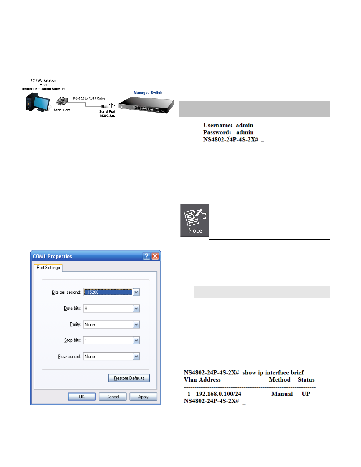
To configure the system, connect a serial cable to a COM port
on a PC or notebook computer and to RJ45 type of serial port
of the Stackable PoE Managed Switch.
Figure 1: Stackable PoE Managed Switch Console
Connectivity
A terminal program is required to make the software
connection to the Managed Switch.
1. Run terminal program on the OS.
2. When the following screen appears, make sure that the
COM port should be configured as:
Baud : 115200
Data bits : 8
Parity : None
Stop bits : 1
Flow control : None
Once the terminal is connected to the device, power on the
Stackable Managed Switch and the terminal will display
“running testing procedures”. Then, the following message
asks to log-in user name and password. The factory default
user name and password are shown as follows and the login
screen in Figure 3 appears.
Username: admin
Password: admin
Figure 3: Stackable PoE Managed Switch Console Login
Screen
The user can now enter commands to manage the Managed
Switch. For a detailed description of the commands, please
refer to the following chapters.
1. For security reason, please change and
memorize the new password after this first
setup.
2. Only accept command in lowercase letter
Configuring IP Address
Figure 2: COM Port Configuration
The Managed Switch is shipped with default IP address shown
below.
IP Address: 192.168.0.100
Subnet Mask: 255.255.255.0
To check the current IP address or modify a new IP address
for the Switch, please use the procedures as follows:
Show the current IP Address
1. At the “#” prompt, enter “show ip interface brief”.
2. The screen displays the current IP address as shown in
Figure 4.
Figure 4: IP Information Screen
2 IFS NS4802-24P-4S-2X Quick Start Guide
Page 3

Configuring IP Address
console command or
” anytime in
3. At the “#” prompt, enter the following command and
press <Enter> as shown in Figure 5.
is configured through an Ethernet connection. Please make
sure the manager PC must be set on the same IP subnet
address.
As the operation of the NS2402 SERIES is the
same as that of the NS2402-16P, the NS240216P is picked to be an example in this guide.
The previous command would apply the following settings for
the Stackable PoE Managed Switch.
IP Address: 192.168.1.100
Subnet Mask: 255.255.255.0
Figure 5: Configuring IP Address Screen
4. Repeat step 1 to check if the IP address is changed.
Store current switch configuration
5. At the “#” prompt, enter the following command and
press <Enter>.
# copy running-config startup-config
For example, the default IP address of the Web Smart PoE
Switch is 192.168.0.100, then the m anager PC should be set
at 192.168.0.x (where x is a number between 1 and 254,
except 100), and the default subnet mask is 255.255.255.0.
Figure 7: IP Management Diagram
Logging in to the Managed Switch
1. Use Internet Explorer 8.0 or above Web browser and
enter IP address http://192.168.0.100
interface.
2. When the following dialog box appears, please enter the
default user name and password “admin”. The login
screen in Figure 8 appears.
to access the Web
Figure 6: Saving Current Configuration Command Screen
If the IP is successfully configured, the Stackable PoE
Managed Switch will apply the new IP address setting
immediately. You can access the Web interface of the
Managed Switch through the new IP address.
If you are not familiar with the
the related parameter, enter “help
console to get the help description.
Starting Web Management
The following shows how to start up the Web Management of
the W eb Smart PoE Switch. Note the Web Smart PoE Switch
Default IP Address: 192.168.0.100
Default Username: admin
Default Password: admin
Figure 8: Login Screen
IFS NS4802-24P-4S-2X Quick Start Guide 3
Page 4

3. After entering the password, the m ain screen appears as
Figure 9 shows.
loaded automatically across a system reboot.
1. Click System, press “Save Startup Config” link to save the
configuration to the startup file.
Figure 9: Web Main Screen of Web Smart PoE Switch
The Switch Menu on the left of the Web page lets you access
all the commands and statistics the Web Smart PoE Switch
provides.
Figure 10: Switch Menu
Now, you can use the Web management interface to continue
the Switch management. For more detailed switch
configuration, please refer to the user’s manual.
2. Press the “Save Configuration” button.
Saving Configuration
In the Stackable PoE Managed Switch, the running
configuration file is stored in the RAM. In the current version,
the running configuration sequence of running-config can be
saved from the RAM to FLASH by executing save startupconfig command, so that the running configuration sequence
becomes the startup configuration file, which is called
configuration save.
To save all applied changes and set the current configuration
as a startup configuration. The startup-configuration file will be
4 IFS NS4802-24P-4S-2X Quick Start Guide
Page 5

Recovering Back to Default Configuration
IP Address has been changed or admin
password has been forgotten –
To reset the IP address to the default IP Address
“192.168.0.100” or reset the login password to default
value, press the hardware reset button on the front
panel for about 10 seconds. After the device is rebooted,
you can login the management Web interface within the
same subnet of 192.168.0.xx.
Figure 11: Stackable PoE Managed Switch Reset Button
Contact information
www.interlogix.com or www.utcfssecurityproducts.eu.
For customer support, see www.interlogix.com/customer-
support .
© 2015 United Technologies Corporation
Interlogix is part of UTC Climate Controls & Security, a unit of
United Technologies Corporation. All rights reserved.
IFS NS4802-24P-4S-2X Quick Start Guide 5
 Loading...