

Interlogix IFS NS3601-24P, IFS NS3601-4S, GE-DSSG-244, GE-DSSG-244-POE, NS3601-24P/4S User Manual
Page 1

IFS NS3601-24P/4S
GE-DSSG-244
GE-DSSG-244-POE
User Manual
P/N 1072570 • REV 00.10 • ISS 13JUN13
Page 2

Copyright
© 2013 UTC Fire & Security Americas Corporation, Inc.
Interlogix is part of UTC Climate Controls & Security, a unit of United
Technologies Corporation. All rights reserved.
Trademarks and patents
The IFS NS3601-24P/4S GE-DSSG-244 GE-DSSG-244-POE and logo
are trademarks of United Technologies.
Other trade names used in this document may be trademarks or
registered trademarks of the manufacturers or vendors of the respective
products.
Intended use
Use this product only for the purpose it was designed for; refer to the
data sheet and user documentation for details. For the latest product
information, contact your local supplier or visit us online at
www.interlogix.com.
Manufacturer
UTC Fire & Security Americas Corporation, Inc.
2955 Red Hill Avenue
Costa Mesa, CA 92626-5923, USA
EU authorized manufacturing representative:
UTC Fire & Security B.V., Kelvinstraat 7,
6003 DH Weert, The Netherlands
Certification
N4131
FCC compliance
This equipment has been tested and found to comply with the limits for a
Class A digital device, pursuant to part 15 of the FCC Rules. These limits
are designed to provide reasonable protection against harmful
interference when the equipment is operated in a commercial
environment. This equipment generates, uses, and can radiate radio
frequency energy and, if not installed and used in accordance with the
instruction manual, may cause harmful interference to radio
communications.
You are cautioned that any changes or modifications not expressly
approved by the party responsible for compliance could void the user's
authority to operate the equipment.
ACMA compliance Notice! This is a Class A product. In a domestic environment this
product may cause radio interference in which case the user may be
required to take adequate measures.
Canada
This Class A digital apparatus complies with Canadian ICES-003.
Cet appareil numérique de la classe A est conforme á la norme
NMB-003du Canada.
European Union directives 2004/108/EC (EMC Directive): Hereby, UTC Fire & Security Americas
Corporation, Inc. declares that this device is in compliance with the
essential requirements and other relevant provisions of Directive
2004/108/EC.
2002/96/EC (WEEE directive): Products marked with this symbol
cannot be disposed of as unsorted municipal waste in the European
Union. For proper recycling, return this product to your local supplier
upon the purchase of equivalent new equipment, or dispose of it at
designated collection points. For more information see:
www.recyclethis.info.
Contact information
Contact support
For contact information see our Web site:
www.interlogix.com/customer support
www.interlogix.com.
Page 3

IFS NS3601-24P/4S GE-DSSG-244 and 244-POE User Manual
TABLE OF CONTENTS
5IFS NS3601-24P/4S GE-DSSG-244 GE-DSSG-244-POE USER MANUAL................. 1
5TABLE OF CONTENTS...................................................................................................1
5INTRODUCTION..............................................................................................................7
5Packet Contents ........................................................................................................................................ 7
5Product Description..................................................................................................................................9
5How to Use This Manual.........................................................................................................................11
5Product Features..................................................................................................................................... 12
5Product Specification ............................................................................................................................. 14
5INSTALLATION .............................................................................................................18
5Hardware Description............................................................................................................................. 18
5Switch Front Panel.............................................................................................................................. 18
5LED Indications................................................................................................................................... 20
5Switch Rear Panel .............................................................................................................................. 22
5Install the Switch.....................................................................................................................................23
5Desktop Installation............................................................................................................................. 23
5Rack Mounting .................................................................................................................................... 25
5Installing the SFP transceiver ............................................................................................................. 26
5Stack Installation..................................................................................................................................... 28
5Connecting Stacking cable ................................................................................................................. 29
5Management Stacking ........................................................................................................................ 30
5SWITCH MANAGEMENT .............................................................................................. 32
5Requirements...........................................................................................................................................32
5Management Access Overview.............................................................................................................. 33
5Administration Console.......................................................................................................................... 33
5SNMP-Based Network Management...................................................................................................... 35
5WEB CONFIGURATION................................................................................................37
5Main Web Page........................................................................................................................................40
5System......................................................................................................................................................42
5System Information ............................................................................................................................. 43
5IP Configuration .................................................................................................................................. 44
5IPv6 Configuration .............................................................................................................................. 45
5Users Configuration ............................................................................................................................ 46
1
Page 4

IFS NS3601-24P/4S GE-DSSG-244 and 244-POE User Manual
5Users Privilege Levels ........................................................................................................................ 49
5NTP Configuration .............................................................................................................................. 51
5UPnP Configuration ............................................................................................................................ 51
5DHCP Relay........................................................................................................................................ 53
5DHCP Relay Statistics ........................................................................................................................ 55
5CPU Load ........................................................................................................................................... 56
5System Log ......................................................................................................................................... 57
5Detailed Log........................................................................................................................................ 58
5Remote Syslog.................................................................................................................................... 58
5SMTP Configure ................................................................................................................................. 60
5Web Firmware Upgrade...................................................................................................................... 61
5TFTP Firmware Upgrade .................................................................................................................... 62
5Configuration Backup.......................................................................................................................... 62
5Configuration Upload .......................................................................................................................... 64
5Factory Default.................................................................................................................................... 66
6System Reboot ................................................................................................................................... 67
6Simple Network Management Protocol................................................................................................. 67
6SNMP Overview.................................................................................................................................. 67
6SNMP System Configuration .............................................................................................................. 68
6SNMP System Information Configuration........................................................................................... 69
6SNMP Trap Configuration................................................................................................................... 69
6SNMPv3 Configuration ....................................................................................................................... 71
6Port Management .................................................................................................................................... 75
6Port Configuration ............................................................................................................................... 75
6Port Statistics Overview ...................................................................................................................... 77
6Port Statistics Detail............................................................................................................................ 79
6SFP Module Information ..................................................................................................................... 80
6Port Mirroring Configuration................................................................................................................ 82
6Link Aggregation..................................................................................................................................... 84
6Static Aggregation Configuration ........................................................................................................ 86
6LACP Configuration ............................................................................................................................ 87
6LACP System Status .......................................................................................................................... 89
6LACP Port Status................................................................................................................................ 89
6LACP Port Statistics............................................................................................................................ 91
6VLAN.........................................................................................................................................................92
6VLAN Overview................................................................................................................................... 92
6IEEE 802.1Q VLAN............................................................................................................................. 92
6VLAN Basic Information...................................................................................................................... 94
6VLAN Port Configuration .................................................................................................................... 95
2
Page 5

IFS NS3601-24P/4S GE-DSSG-244 and 244-POE User Manual
6VLAN Membership Configuration ....................................................................................................... 99
6VLAN Membership Status for User Static......................................................................................... 100
6VLAN Port Status for User Static...................................................................................................... 101
6Port Isolation Configuration .............................................................................................................. 102
6Private VLAN Membership Configuration ......................................................................................... 105
6VLAN setting example: ..................................................................................................................... 106
6Spanning Tree Protocol........................................................................................................................ 113
6Theory............................................................................................................................................... 113
6STP Bridge Configuration ................................................................................................................. 118
6Bridge Status .................................................................................................................................... 119
6CIST Port Configuration.................................................................................................................... 120
6MSTI Priorities .................................................................................................................................. 123
6MSTI Configuration ........................................................................................................................... 124
6MSTI Ports Configuration ................................................................................................................. 125
6Port Status ........................................................................................................................................ 127
6Port Statistics .................................................................................................................................... 128
6Multicast................................................................................................................................................. 129
6IGMP Snooping................................................................................................................................. 129
6IGMP Snooping Configuration .......................................................................................................... 133
6IGMP Port Related Configuration ..................................................................................................... 133
6VLAN Configuration .......................................................................................................................... 135
6Port Group Filtering........................................................................................................................... 136
6IGMP Snooping Status ..................................................................................................................... 137
6MVR Configuration............................................................................................................................ 139
6MVR Status....................................................................................................................................... 141
6Quality of Service..................................................................................................................................142
7Understand QOS .............................................................................................................................. 142
7QCL Configuration Wizard................................................................................................................ 142
7QoS Control List Configuration ......................................................................................................... 149
7Port QoS Configuration..................................................................................................................... 151
7Bandwidth Control............................................................................................................................. 153
7Storm Control Configuration ............................................................................................................. 155
7QoS Statistics ................................................................................................................................... 155
7DSCP Remarking.............................................................................................................................. 157
7Voice VLAN Configuration ................................................................................................................ 158
7Voice VLAN OUI Table ..................................................................................................................... 161
7Access Control Lists............................................................................................................................. 161
7Access Control List Status ................................................................................................................ 162
7Access Control List Configuration..................................................................................................... 163
3
Page 6

IFS NS3601-24P/4S GE-DSSG-244 and 244-POE User Manual
7ACE Configuration ............................................................................................................................ 164
7ACL Ports Configuration ................................................................................................................... 169
7ACL Rate Limiter Configuration ........................................................................................................ 171
7Understanding IEEE 802.1X Port-Based Authentication.................................................................. 173
7Authentication Configuration............................................................................................................. 175
7Network Access Server Configuration .............................................................................................. 176
7Network Access Overview ................................................................................................................ 184
7Network Access Statistics................................................................................................................. 185
7Authentication Server Configuration ................................................................................................. 190
7RADIUS Overview ............................................................................................................................ 192
7RADIUS Details ................................................................................................................................ 194
7Windows Platform RADIUS Server Configuration ............................................................................ 198
74.11.10 802.1X Client Configuration................................................................................................. 203
7Security ..................................................................................................................................................205
7Port Limit Control .............................................................................................................................. 205
7Access Management ........................................................................................................................ 208
7Access Management Statistics......................................................................................................... 209
7HTTPs............................................................................................................................................... 210
7SSH ................................................................................................................................................. 210
7Port Security Status .......................................................................................................................... 211
7Port Security Detail ........................................................................................................................... 213
7DHCP Snooping................................................................................................................................ 213
7DHCP Snooping Statistics ................................................................................................................ 215
7IP Source Guard Configuration......................................................................................................... 217
7IP Source Guard Static Table ........................................................................................................... 218
7ARP Inspection ................................................................................................................................. 219
7ARP Inspection Static Table ............................................................................................................. 220
7Address Table........................................................................................................................................ 221
7MAC Address Table Configuration ................................................................................................... 221
7Static MAC Table Configuration ....................................................................................................... 221
7MAC Address Table Status .............................................................................................................. 223
7MAC Table Learning......................................................................................................................... 224
7Dynamic ARP Inspection Table ........................................................................................................ 225
7Dynamic IP Source Guard Table ...................................................................................................... 226
7LLDP....................................................................................................................................................... 227
7Link Layer Discovery Protocol .......................................................................................................... 227
7LLDP Configuration........................................................................................................................... 227
8LLDPMED Configuration .................................................................................................................. 229
8LLDP-MED Neighbor ........................................................................................................................ 234
4
Page 7

IFS NS3601-24P/4S GE-DSSG-244 and 244-POE User Manual
8Neighbor ........................................................................................................................................... 236
8Port Statistics .................................................................................................................................... 237
8Network Diagnostics............................................................................................................................. 239
8Ping ................................................................................................................................................. 239
8IPv6 Ping........................................................................................................................................... 240
8Remote IP Ping Test......................................................................................................................... 241
8Cable Diagnostics ............................................................................................................................. 242
8Power over Ethernet (GE-DSSG-244-POE / NS3601-24P/4S)............................................................ 243
8Power over Ethernet Powered Device.............................................................................................. 244
8Power Configuration ......................................................................................................................... 244
8Port Configuration ............................................................................................................................. 247
8PoE Status ........................................................................................................................................ 248
8PoE Schedule ................................................................................................................................... 250
8LLDP Neighbor Power Over Ethernet............................................................................................... 251
8Stack ................................................................................................................................................. 253
8Stack Configuration........................................................................................................................... 255
8Stack Information .............................................................................................................................. 257
8Stack Port State Overview................................................................................................................ 258
8Stack Example .................................................................................................................................. 259
8COMMAND LINE INTERFACE.................................................................................... 263
8Accessing the CLI ................................................................................................................................. 263
8Telnet Login........................................................................................................................................... 265
8COMMAND LINE MODE.............................................................................................. 266
8System Command.................................................................................................................................267
8Stack.......................................................................................................................................................270
8IP Command...........................................................................................................................................272
8Port Management Command................................................................................................................277
8MAC Address Table Command............................................................................................................ 281
8VLAN Configuration Command ...........................................................................................................285
8Private VLAN Configuration Command.............................................................................................. 290
8Security Command................................................................................................................................ 292
8Spanning Tree Protocol Command.....................................................................................................336
8Multicast Configuration Command......................................................................................................345
8Link Aggregation Command................................................................................................................349
8Link Aggregation Control Protocol Command................................................................................... 350
8LLDP Command.....................................................................................................................................353
8LLDPMED Command ............................................................................................................................ 356
8Power over Ethernet Command........................................................................................................... 360
5
Page 8

IFS NS3601-24P/4S GE-DSSG-244 and 244-POE User Manual
8Quality of Service Command ............................................................................................................... 363
8Mirror Command....................................................................................................................................369
8Configuration Command...................................................................................................................... 370
8Firmware Command.............................................................................................................................. 371
8UPnP Command .................................................................................................................................... 371
8MVR Command...................................................................................................................................... 372
8Voice VLAN Command .........................................................................................................................375
8SMTP Command.................................................................................................................................... 379
8Show Command .................................................................................................................................... 382
8SWITCH OPERATION................................................................................................. 385
9Address Table........................................................................................................................................ 385
9Learning .................................................................................................................................................385
9Forwarding & Filtering..........................................................................................................................385
9Store-and-Forward ................................................................................................................................ 385
9Auto-Negotiation ................................................................................................................................... 385
9POWER OVER ETHERNET OVERVIEW .................................................................... 387
9What is PoE?..........................................................................................................................................387
9The PoE Provision Process.................................................................................................................. 388
9Stages of powering up a PoE link..................................................................................................... 389
9Line Detection ................................................................................................................................... 389
9Classification..................................................................................................................................... 389
9Start-up ............................................................................................................................................. 389
9Operation .......................................................................................................................................... 389
9Power Disconnection Scenarios ....................................................................................................... 389
9TROUBLE SHOOTING................................................................................................ 391
9APPENDEX A..............................................................................................................392
9Switch's RJ-45 Pin Assignments......................................................................................................... 392
910/100Mbps, 10/100Base-TX.................................................................................................................392
9APPENDEX B : GLOSSARY....................................................................................... 394
9APPENDIX C: LOCAL USER PRIVILEGE LEVEL TABLE......................................... 407
6
Page 9

IFS NS3601-24P/4S GE-DSSG-244 and 244-POE User Manual
INTRODUCTION
The IFS Layer 2 Managed Gigabit Switch series NS3601-24P/4S, GE-DSSG-244, and GE-DSSG-244-POE are 24-port Gigabit
Ethernet Switches with SFP fiber ports and robust layer 2 features. The description of these models is shown below:
GE-DSSG-244
NS3601-24P/4S 24-Port 10/100/1000Base-T PoE Managed Stackable Switch / 380W / IEEE 802.3af
GE-DSSG-244-POE 24-Port 100/1000Base- T PoE Managed Stackable Switch / 220W / IEEE 802.3af
Terms of “Managed Switch” refers to the switches listed above.
Packet Contents
Open the box of the Managed Switch and carefully unpack it. The box should contain the following items:
Check the contents of your package for following parts:
; The Managed Switch
24-Port 100/1000Base-X with 8 Shared TP Managed Stackable Fiber Switch
x1
; User’s manual CD
; Quick installation guide
; 19” Rack mount accessory kit
; Power cord
; Rubber feet
; RS-232 DB9 male Console cable
; CB-STX50 – 50cm stack cable
If any of these are missing or damaged, please contact your distributor or IFS sales rep immediately, if possible, retain the original
carton and packaging material in case you need to return the product for repair/replacement.
x1
x1
x1
x1
X4
x1
x1
7
Page 10

Page 11

IFS NS3601-24P/4S GE-DSSG-244 and 244-POE User Manual
Product Description
Cost-effective IPv6 Managed Gigabit Switch solution for SMB
Nowadays, lots of electronic products or mobile devices can browse the Internet, which means the need of IP Address increases.
However, the current IPv4 network infrastructure is not capable enough to provide IP Address to each single users/Clients. The
situation forces the ISP to build up the IPv6 (Internet Protocol version 6) network infrastructure speedily. To fulfill the demand,
IFS releases the IPv6 management Gigabit Ethernet Switch, IFS- series Managed Switch. It supports both IPv4 and IPv6
management functions. It can work with original network structure (IPv4) and also support the new network structure (IPv6) in the
future. With easy and friendly management interfaces and plenty of management functions included, the IFS- series Managed
Switch is the best choice for ISP to build the IPv6 FTTx edge service and for SMB to connect with IPv6 network.
High-Performance / Cost-effective / Telecom class Gigabit solution for Enterprise backbone and Data Center Networking
The IFS Managed Switch is a L2/L4 Managed Gigabit Switch. Since Gigabit network interface had become the basic equipment
and requirement of Enterprise and Network Servers, with 48Gbps switching fabric, the Managed Switch can handle extremely
large amounts of data in a secure topology linking to a backbone or high capacity servers. The powerful QoS and Network
Security features make it to meets the needs of effective data traffic control for both Campus and Enterprise, such VoIP, video
streaming and multicast application.
High Performance
The Managed Switch provides 24 10/100/1000Mbps (or 100/1000Mbps for GE-DSSG-244 fiber switch)
with 4 shared Gigabit SFP slots. It has a high performance switch architecture that is capable of providing non-blocking switch
fabric and wire-speed throughput as high as 48Gbps, which greatly simplifies the tasks of upgrading the LAN for catering to
increase bandwidth demands.
Robust Layer 2 Features
The Managed Switch can be programmed for basic switch management functions such as port speed configuration, Port
aggregation, VLAN, Spanning Tree protocol, QoS, bandwidth control and IGMP Snooping. The Managed Switch provides 802.1Q
Tagged VLAN, Q-in-Q VLAN trunning and private VLAN, the VLAN groups allowed on the Managed Switch will be maximally up to
255. Via supporting port aggregation, the Managed Switch allows the operation of a high-speed trunk combining multiple ports, up
to 12 Trunk groups, and up to 16 ports per trunk group, and it supports fail-over as well.
Excellent Traffic Control
The Managed Switch is equipped with powerful traffic management and QoS features to enhance services offered by telecoms.
The functionality includes QoS features such as wire-speed Layer 4 traffic classifiers and bandwidth limiting that are particular
useful for multi-tenant unit, multi business unit, Telco, or Network Service Provide applications. It also empowers the enterprises
to take full advantages of the limited network resources and guarantees the best performance at VoIP and Video conferencing
transmission.
Gigabit Ethernet ports
9
Page 12
Efficient Management
For efficient management, the series of Managed Switch is equipped with console, WEB and SNMP management interfaces. With
its built-in Web-based management, it offers an easy-to-use, platform-independent management and configuration facility. The
Managed Switch supports standard Simple Network Management Protocol (SNMP) and can be managed via any standard-based
management software. For text-based management, it can also be accessed via Telnet and the console port.
Powerful Security
The Managed Switch offers comprehensive Access Control List (ACL) for enforcing security to the edge. Its protection
mechanisms also comprise of port-based 802.1x and MAC-based user and device authentication. The port-security is effective in
limit the numbers of clients pass through, so that network administrators can now construct highly secured corporate networks
with time and effort considerably less than before.
Flexibility and Extension solution
The 4 mini-GBIC slots are compatible with 1000Base-SX/LX and WDM SFP (Small Factor Pluggable) fiber-optic modules. The
distance can be extended from 550 meters (Multi-Mode fiber) up to above 10/20/30/40/5060//70 kilometers (Single-Mode fiber or
WDM fiber). They are well suited for using within the enterprise data centers and distributions.
Reliable Stacking Management
The IFS Series Managed Switch provides a switch stacking function to manage up to 16 switches using a single IP address. That
helps network managers to easily configure switches via one single IP address instead of connecting and setting each unit one by
one. Through its high bandwidth tunnel and stacking technology, it gives enterprise, service provider and telcom flexible control
over port density, uplinks and switch stack performance. Up to 384 Gigabit Ethernet ports can be managed by a stacking group
and you can add ports and functionality as needed. The stacking technology also enables the advantages of chassis-based
switches to be integrated into IFS Series Managed Switch, but without the expensive up-front cost.
Advanced Features and Centralized Power Management for Enterprise and Campus PoE Networking (PoE Model)
The IFS GE-DSSG-244-POE and NS3601-24P/4S series PoE switches provides 24 10/100/1000Mbps Power-over-Ethernet (PoE,
IEEE 802.3af compliant) ports which optimize the installation and power management of network devices such as wireless access
points (AP), Voice over IP (VoIP) phones, and security video cameras. The PoE capabilities also help to reduce deployment costs
for network devices like the wireless AP as a result of freeing from restrictions of power outlet locations. Power and data switching
are integrated into one unit and delivered over a single cable. It thus eliminates cost for additional AC wiring and reduces
installation time.
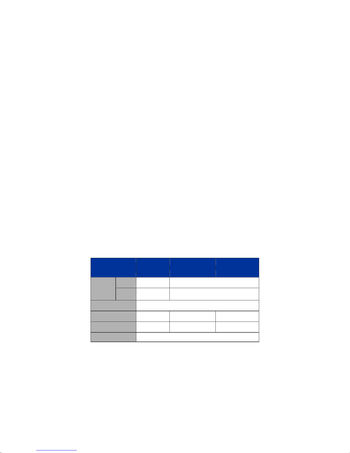
The below table lists the major hardware difference between the series model:
Model
(IFS)
Copper
Interface
Redundant Power
PoE Mode
PoE Budget
Stack Capability
Fiber 24, 100FX
GE-DSSG-244 GE-DSSG-244-POE NS3601-24P/4S
8 24
compatible
- af af
-
Hardware stacking, up to 16 units
4, 100FX compatible
-
220W 380W
10
Page 13

IFS NS3601-24P/4S GE-DSSG-244 and 244-POE User Manual
How to Use This Manual
This User Manual is structured as follows:
Section 2, INSTALLATION
The section explains the functions of the Switch and how to physically install the Managed Switch.
Section 3, SWITCH MANAGEMENT
The section contains the information about the software function of the Managed Switch.
Section 4, WEB CONFIGURATION
The section explains how to manage the Managed Switch by Web interface.
Section 5, COMMAND LINE INTERFACE
The section describes how to use the Command Line interface (CLI).
Section 6, CLI CONFIGURATION
The section explains how to manage the Managed Switch by Command Line interface.
Section 7, SWITCH OPERATION
The chapter explains how to does the switch operation of the Managed Switch.
Section 8, POWER OVER ETHERNET OVERVIEW
The chapter introduce the IEEE 802.3af PoE standard and PoE provision of the Managed Switch.
Section 9, TROUBSHOOTING
The chapter explains how to trouble shooting of the Managed Switch.
Appendix A
The section contains cable information of the Managed Switch.
11
Page 14

IFS NS3601-24P/4S GE-DSSG-244 and 244-POE User Manual
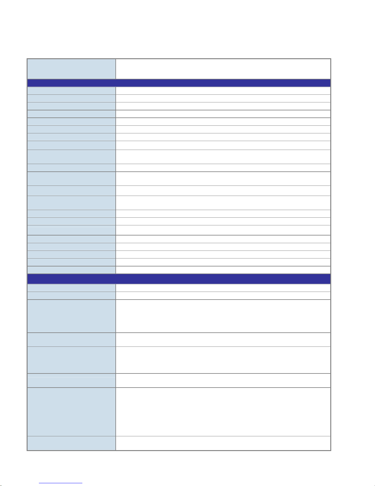
Product Features
¾ Physical Port
NS3601-24P/4S / GE-DSSG-244-POE
24-Port 10/100/1000Base-T Gigabit Ethernet RJ-45 with IEEE 802.3af PoE Injector
4 100/1000Base-X SFP slots, shared with Port-21 to Port-24
RS-232 DB9 console interface for Switch basic management and setup
2 High-performance 5GbE Stacking interface
GE-DSSG-244
24 100/1000Base-X mini-GBIC/SFP slots
8-Port 10/100/1000Base-T Gigabit Ethernet RJ-45, shared with Port-1 to Port-8
RS-232 DB9 console interface for Switch basic management and setup
2 High-performance 5GbE Stacking interface
¾ Layer 2 Features
■ Prevents packet loss with back pressure (Half-Duplex) and IEEE 802.3x PAUSE frame flow control (Full-Duplex)
■ High performance of Store-and-Forward architecture, broadcast storm control and runt/CRC filtering eliminates erroneous
packets to optimize the network bandwidth
■ Storm Control support:
− Broadcast / Multicast / Unknown-Unicast
■ Support VLAN
− IEEE 802.1Q Tagged VLAN
− Up to 255 VLANs groups, out of 4094 VLAN IDs
− Provider Bridging (VLAN Q-in-Q) support (IEEE 802.1ad)
− Private VLAN Edge (PVE)
− Voice VLAN
■ Support Spanning Tree Protocol
− STP, IEEE 802.1D Spanning Tree Protocol
− RSTP, IEEE 802.1w Rapid Spanning Tree Protocol
− MSTP, IEEE 802.1s Multiple Spanning Tree Protocol, spanning tree by VLAN
− BPDU Guard
■ Support Link Aggregation
− 802.3ad Link Aggregation Control Protocol (LACP)
− Cisco ether-channel (Static Trunk)
− Maximum 12 trunk groups, up to 16 ports per trunk group
− Up to 16Gbps bandwidth(Duplex Mode)
■ Provide Port Mirror (many-to-1)
■ Port Mirroring to monitor the incoming or outgoing traffic on a particular port
¾ Quality of Service
■ Ingress Shaper and Egress Rate Limit per port bandwidth control
■ 4 priority queues on all switch ports
■ Traffic classification:
- IEEE 802.1p CoS
- TOS / DSCP / IP Precedence of IPv4/IPv6 packets
- IP TCP/UDP port number
- Typical network application
■ Strict priority and Weighted Round Robin (WRR) CoS policies
■ Supports QoS and In/Out bandwidth control on each port
■ Traffic-policing policies on the switch port
■ QoS Control List Wizard makes QoS creation and configuration easier and more quickly
12
Page 15

IFS NS3601-24P/4S GE-DSSG-244 and 244-POE User Manual
■ DSCP remarking
¾ Multicast
■ Supports IGMP Snooping v1, v2 and v3
■ Querier mode support
■ IGMP Snooping port filtering
■ Multicast VLAN Registration (MVR) support
¾ Security
■ IEEE 802.1x Port-Based / MAC-Based network access authentication
■ Built-in RADIUS client to co-operate with the RADIUS servers
■ TACACS+ login users access authentication
■ RADIUS / TACACS+ users access authentication
■ IP-Based Access Control List (ACL)
■ MAC-Based Access Control List
■ Source MAC / IP address binding
■ DHCP Snooping to filter un-trusted DHCP messages
■ Dynamic ARP Inspection discards ARP packets with invalid MAC address to IP address binding
■ IP Source Guard prevents IP spoofing attacks
■ Auto DoS rule to defend DoS attack
■ IP address access management to prevent unauthorized intruder
¾ Management
■ Switch Management Interfaces
- Console / Telnet Command Line Interface
- Web switch management
- SNMP v1, v2c, and v3 switch management
- SSH / SSL secure access
■ Four RMON groups (history, statistics, alarms, and events)
■ IPv6 IP Address / NTP / DNS management
■ Built-in Trivial File Transfer Protocol (TFTP) client
■ BOOTP and DHCP for IP address assignment
■ Firmware upload/download via HTTP / TFTP
■ DHCP Relay
■ User Privilege levels control
■ NTP (Network Time Protocol)
■ Link Layer Discovery Protocol (LLDP) Protocol
■ Cable Diagnostic technology provides the mechanism to detect and report potential cabling issues
■ Reset button for system reboot or reset to factory default
■ IFS Smart Discovery Utility for deploy management
■ ICMPv6
¾ Stacking
■ Hardware stack up to 16 units and 384 ports
■ Stacking architecture supports Chain and Ring mode
■ Mirror across stack
■ Link Aggregation groups spanning multiple switches in a stack
■ Hardware learning with MAC table synchronization across stack
¾ Power over Ethernet (NS3601-24P/4S / GE-DSSG-244-POE)
■ Complies with IEEE 802.3af Power over Ethernet End-Span PSE
■ Up to 24 ports for IEEE 802.3af devices powered
■ Support PoE Power up to 15.4 watts for each PoE ports
■ Auto detect powered device (PD)
■ Circuit protection prevent power interference between ports
■ Remote power feeding up to 100m
■ PoE Management
■ Total PoE power budget control
■ Per port PoE function enable/disable
■ PoE Port Power feeding priority
■ Per PoE port power limit
■ PD classification detection
13
Page 16
IFS NS3601-24P/4S GE-DSSG-244 and 244-POE User Manual
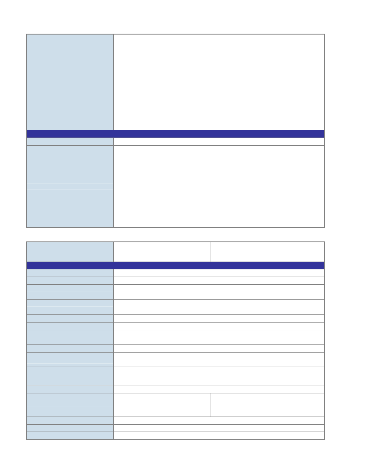
Product Specification
IFS Stackable Fiber Switch
Product GE-DSSG-244
Hardware Specification
Copper Ports
SFP/mini-GBIC Slots
Console Port
Stacking Ports
Switch Fabric
Address Table
Share data Buffer
Switch Processing Scheme
Flow Control
Jumbo Frame
Reset Button
Dimension (W x D x H)
Weight
LED
Power Consumption
Power Requirement – AC
Power Requirement – DC
Stacking Numbers
Stacking Bandwidth
Stack ID Display
ESD Protection
Layer 2 Function
Basic Management Interfaces
Secure Management Interface
Port configuration
Port Status
VLAN
Port trunking
QoS
IGMP Snooping
8 10/ 100/1000Base-T RJ-45 Auto-MDI/MDI-X ports, shared with Port-1~Port-8
24 100/1000Base-X Dual Speed SFP interfaces
1 x RS-232 DB9 serial port (115200, 8, N, 1)
2 5GbE / Cross-HDMI interface
68Gbps / non-blocking
8K entries, automatic source address learning and ageing
1392 kilobytes
Store-and-Forward
IEEE 802.3x Pause Frame for Full-Duplex
Back pressure for Half-Duplex
10Kbytes
< 5 seconds: System reboot
> 10 seconds: Factory Default
440 x 200 x 44.5 mm, 1U high
3.0kg
Power, Link/Act and speed per Gigabit port
Max. 30.2 watts / 102.98 BTU
AC 100~240V, 50/60Hz
---
16
10Gbps Full-Duplex
7-Segment LED Display (1~9, A~F,0)
6KV DC
Console, Telnet, Web Browser, SNMPv1, v2c and v3
SSH, SSL, SNMP v3
Port disable/enable.
Auto-negotiation 10/100/1000Mbps full and half duplex mode selection.
Flow Control disable / enable.
Bandwidth control on each port.
Power saving mode control
Display each port’s speed duplex mode, link status, Flow control status.
Auto negotiation status, trunk status.
802.1Q Tagged Based VLAN ,up to 255 VLAN groups
Q-in-Q
Private VLAN
Voice VLAN
IEEE 802.3ad LACP / Static Trunk
Support maximum of 12 trunk groups, up to 16 ports per trunk group.
Traffic classification based, Strict priority and WRR
4-level priority queues on all switch ports: Low, Normal, Medium, High.
Different action on QCL Configuration:
- Set up Port Policies
- Set up Typical Network Application Rules
- Set up ToS Precedence Mapping
- Set up VLAN Tag Priority Mapping
IGMP (v1/v2/v3) Snooping, up to 255 multicast Groups
IGMP Querier mode support
14
Page 17
Access Control List
SNMP MIBs
Standards Conformance
Regulation Compliance
Standards Compliance
IFS Stackable PoE models
IFS NS3601-24P/4S GE-DSSG-244 and 244-POE User Manual
IP-Based ACL / MAC-Based ACL
Up to 256 entries
RFC-1213 MIB-II
IF-MIB
RFC-1493 Bridge MIB
RFC-1643 Ethernet MIB
RFC-2863 Interface MIB
RFC-2665 Ether-Like MIB
RFC-2737 Entity MIB
RFC-2618 RADIUS Client MIB
RFC-2933 IGMP-STD-MIB
RFC3411 SNMP-Frameworks-MIB
IEEE 802.1X PAE
LLDP
MAU-MIB
FCC Part 15 Class A, CE
IEEE 802.3 10Base-T
IEEE 802.3u 100Base-TX/100Base-FX
IEEE 802.3z Gigabit SX/LX
IEEE 802.3ab Gigabit 1000T
IEEE 802.3x Flow Control and Back pressure
IEEE 802.3ad Port trunk with LACP
IEEE 802.1D Spanning Tree protocol
IEEE 802.1w Rapid Spanning Tree protocol
IEEE 802.1s Multiple Spanning Tree
IEEE 802.1p Class of service
IEEE 802.1Q VLAN Tagging
IEEE 802.1x Port Authentication Network Control
IEEE 802.1ab Link Layer Discovery Protocol (LLDP)
Product GE-DSSG-244-POE NS3601-24P/4S
Hardware Specification
Copper Ports
SFP/mini-GBIC Slots
Console Port
Stacking Ports
Switch Fabric
Address Table
Share data Buffer
Switch Processing Scheme
Flow Control
Jumbo Frame
Reset Button
Dimension (W x D x H)
Weight
LED
Power Consumption
Power Requirement – AC
Stacking Numbers
Stacking Bandwidth
Stack ID Display
24 10/ 100/1000Base-T RJ-45 Auto-MDI/MDI-X ports
4 SFP interfaces, shared with Port-21 to Port-24
1 x RS-232 DB9 serial port (115200, 8, N, 1)
2 5GbE / Cross-HDMI interface
68Gbps / non-blocking
8K entries, automatic source address learning and ageing
1392 kilobytes
Store-and-Forward
IEEE 802.3x Pause Frame for Full-Duplex
Back pressure for Half-Duplex
10Kbytes
< 5 seconds: System reboot
> 10 seconds: Factory Default
440 x 300 x 44.5 mm, 1U high
4.5kg
Power, Link/Act and speed per Gigabit port
Max. 290 watts /
989 BTU
AC 100~240V, 50/60Hz AC 100~240V, 50/60Hz
16
10Gbps Full-Duplex
7-Segment LED Display (1~9, A~F,0)
Max. 430.2 watts /
1467 BTU
15
Page 18
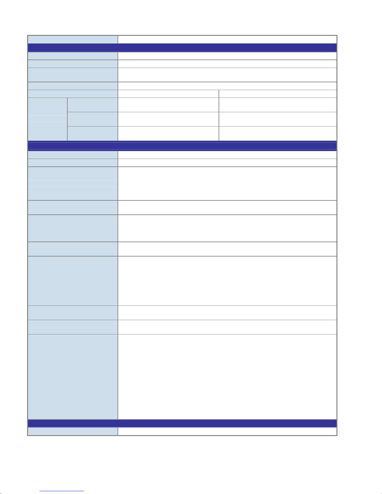
ESD Protection
Power over Ethernet
PoE Standard
PoE Power Supply Type
PoE Power Output
Power Pin Assignment
PoE Power Budget
Number of PD @
7Watts
PoE Ability
Layer 2 Function
Basic Management Interfaces
Secure Management Interface
Port configuration
Port Status
VLAN
Port trunking
QoS
IGMP Snooping
Access Control List
SNMP MIBs
Standards Conformance
Regulation Compliance
Number of PD @
15.4Watts
Number of PD @
30.8Watts
IFS NS3601-24P/4S GE-DSSG-244 and 244-POE User Manual
6KV DC
IEEE 802.3af PoE / PSE
End-Span
Per Port 48V DC.
Max. 15.4 watts
1/2(+), 3/6(-)
220 Watts 380 Watts
24 24
14 24
- -
Console, Telnet, Web Browser, SNMPv1, v2c and v3
SSH, SSL, SNMP v3
Port disable/enable.
Auto-negotiation 10/100/1000Mbps full and half duplex mode selection.
Flow Control disable / enable.
Bandwidth control on each port.
Power saving mode control
Display each port’s speed duplex mode, link status, Flow control status.
Auto negotiation status, trunk status.
802.1Q Tagged Based VLAN ,up to 255 VLAN groups
Q-in-Q
Private VLAN
Voice VLAN
IEEE 802.3ad LACP / Static Trunk
Support maximum of 12 trunk groups, up to 16 ports per trunk group.
Traffic classification based, Strict priority and WRR
4-level priority queues on all switch ports: Low, Normal, Medium, High.
Different action on QCL Configuration:
- Set up Port Policies
- Set up Typical Network Application Rules
- Set up ToS Precedence Mapping
- Set up VLAN Tag Priority Mapping
IGMP (v1/v2/v3) Snooping, up to 255 multicast Groups
IGMP Querier mode support
IP-Based ACL / MAC-Based ACL
Up to 256 entries
RFC-1213 MIB-II
IF-MIB
RFC-1493 Bridge MIB
RFC-1643 Ethernet MIB
RFC-2863 Interface MIB
RFC-2665 Ether-Like MIB
RFC-2737 Entity MIB
RFC-2618 RADIUS Client MIB
RFC-2933 IGMP-STD-MIB
RFC3411 SNMP-Frameworks-MIB
IEEE 802.1X PAE
LLDP
MAU-MIB
FCC Part 15 Class A, CE
16
Page 19

IFS NS3601-24P/4S GE-DSSG-244 and 244-POE User Manual
IEEE 802.3 10Base-T
IEEE 802.3u 100Base-TX/100Base-FX
IEEE 802.3z Gigabit SX/LX
IEEE 802.3ab Gigabit 1000T
IEEE 802.3x Flow Control and Back pressure
IEEE 802.3ad Port trunk with LACP
IEEE 802.1d Spanning tree protocol
IEEE 802.1w Rapid spanning tree protocol
IEEE 802.1s Multiple spanning tree protocol
IEEE 802.1p Class of service
Standards Compliance
Note: The PoE networks of this equipment is to be connected without routing to the outside plant.
IEEE 802.1Q VLAN Tagging
IEEE 802.1x Port Authentication Network Control
IEEE 802.1ab LLDP
RFC 768 UDP
RFC 793 TFTP
RFC 791 IP
RFC 792 ICMP
RFC 2068 HTTP
RFC 1112 IGMP version 1
RFC 2236 IGMP version 2
RFC 3376 IGMP version 3
IEEE 802.3af Power over Ethernet
17
Page 20
IFS NS3601-24P/4S GE-DSSG-244 and 244-POE User Manual
INSTALLATION
This section describes the hardware features and installation of the Managed Switch on the desktop or rack mount. For easier
management and control of the Managed Switch, familiarize yourself with its display indicators, and ports. Front panel illustrations in
this chapter display the unit LED indicators. Before connecting any network device to the Managed Switch, please read this chapter
completely.
Hardware Description
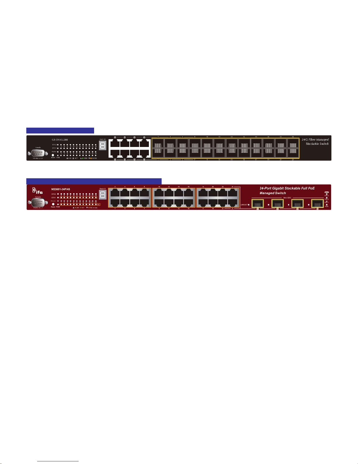
Switch Front Panel
The unit front panel provides a simple interface monitoring the switch. Figure 2-1 to 2-2 shows the front panel of the Managed
Switches.
GE-DSSG-244 Front Panel
Figure 2-1 GE-DSSG-244 front panel.
IFS NS3601-24P/4S / GE-DSSG-244-POE Front Panel
Figure 2-2 IFS NS3601-24P/4S / GE-DSSG-244-POE front panel.
■ Gigabit TP interface
10/100/1000Base-T Copper, RJ-45 Twist-Pair: Up to 100 meters.
■ Gigabit SFP slots
1000Base-SX/LX mini-GBIC slot, SFP (Small Factor Pluggable) transceiver module: From 550 meters (Multi-mode fiber), up to
10/30/5060//70 kilometers (Single-mode fiber).
■ Console Port
The console port is a DB9, RS-232 male serial port connector. It is an interface for connecting a terminal directly. Through the
console port, it provides rich diagnostic information includes IP Address setting, factory reset, port management, link status and
system setting. Users can use the attached RS-232 cable in the package and connect to the console port on the device. After
the connection, users can run any terminal emulation program (Hyper Terminal, ProComm Plus, Telix, Winterm, etc.) to enter
the startup screen of the device.
18
Page 21
IFS NS3601-24P/4S GE-DSSG-244 and 244-POE User Manual
■ Reset button
On the left hand side of the front panel, the reset button is designed for rebooting the Managed Switch without a power cycle.
The following is the summary table of Reset button functions:
Reset Button Pressed and Released Function
< 5 sec: System reboot Reboot the Managed Switch
Reset the Managed Switch to Factory Default configuration.
The Managed Switch will then reboot and load the default
settings as below:
> 10 sec: Factory Default
■ Stack ID
Each IFS Managed Stackable Switch on a stack must have a unique “Stack ID”. There are 16 degrees (0~9, A~F) in the rotary
switch. The Stack ID is configured via Web or CLI management interface. Use the Stack ID to identify the location of the real
device.
。 Default Username: admin
。 Default Password: admin
。 Default IP address: 192.168.0.100
。 Subnet mask: 255.255.255.0
。 Default Gateway: 192.168.0.254
Stack ID is not equal to the Master Priority that is configured in the management interface.
■ Master LED
If master switch fails or is disconnected to the switch by stack port, the switch with lowest switch ID will become the master.
19
Page 22
IFS NS3601-24P/4S GE-DSSG-244 and 244-POE User Manual
LED Indications
The front panel LEDs indicates instant status of port links, data activity and system power; helps monitor and troubleshoot when
needed. Figure 2-3 & Figure 2-4 shows the LED indications of these Managed Switches.
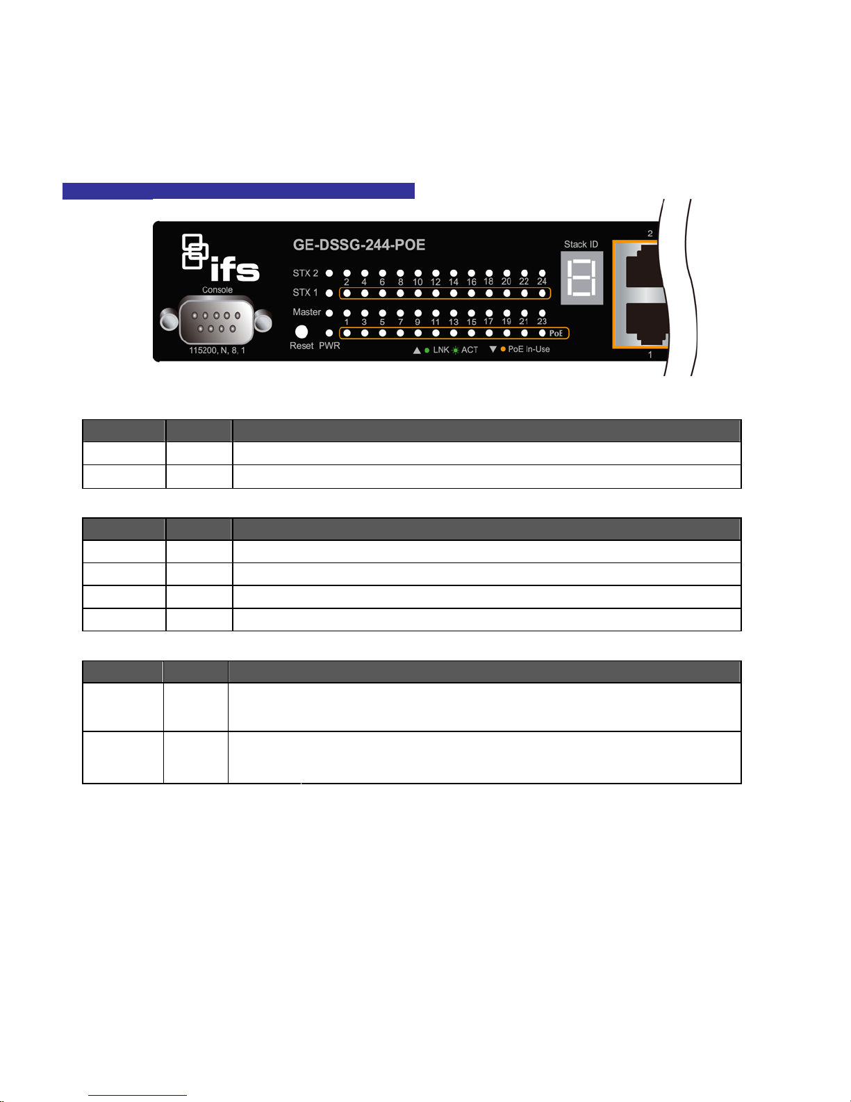
NS3601-24P/4S /GE-DSSG-244-POE LED indication
Figure 2-3 GE-DSSG-244-POE / NS3601-24P/4S LED panel
System
LED Color Function
PWR Green Illuminates to indicate that the Switch has power.
SYS Green Illuminates to indicate the system is on.
Alert
LED Color Function
PWR Alert Green
FAN1 Green
FAN2 Green
FAN3 Green
Per 10/100Mbps port, PoE interfaces (Port-1 to Por-24)
LED Color Function
LNK/ACT Green
PoE In-Use Orange
Illuminates to indicate that the PoE power supply has failed.
Illuminates to indicate that the FAN1 has failed.
Illuminates to indicate that the FAN2 has failed.
Illuminates to indicate that the FAN3 has failed.
Illuminates:
Blink:
Illuminates:
Off:
To indicate the link through that port is successfully established.
To indicate that the Switch is actively sending or receiving data over that port.
To indicate the port is providing 52V DC in-line power.
To indicate the connected device is not a PoE Powered Device (PD).
20
Page 23
Per 10/100/1000B ase-T port / SFP interfaces
LED Color Function
Illuminates:
Blink:
Off:
Illuminates:
Blink:
Off:
1000
LNK/ACT
10/100
LNK/ACT
Green
Green
1. Press the RESET button for 5 seconds. The Managed Switch will reboot automatically.
2. Press the RESET button for 10 seconds . The Managed Switch will restore back to the factory default
mode; the entire configuration will be erased.
IFS NS3601-24P/4S GE-DSSG-244 and 244-POE User Manual
To indicate the link through that port is successfully established with speed
1000Mbps.
To indicate that the Switch is actively sending or receiving data over that port.
If 10/100 LNK/ACT LED is light, it indicates that the port is operating at
10Mbps or 100Mbps. If LNK/ACT LED is Off, it indicates that the port is link
down.
To indicate the link through that port is successfully established with speed
10Mbps or 100Mbps.
To indicate that the Switch is actively sending or receiving data over that port.
If 1000 LNK/ACT LED is ON, it indicates that the port is operating at
1000Mbps.
If 1000 LNK/ACT LED is Off, it indicates that the port is link down.
3. The 2 Gigabit TP/SFP combo ports are shared with port 25/26 of Managed Switch. Either of them can
operate at the same time.
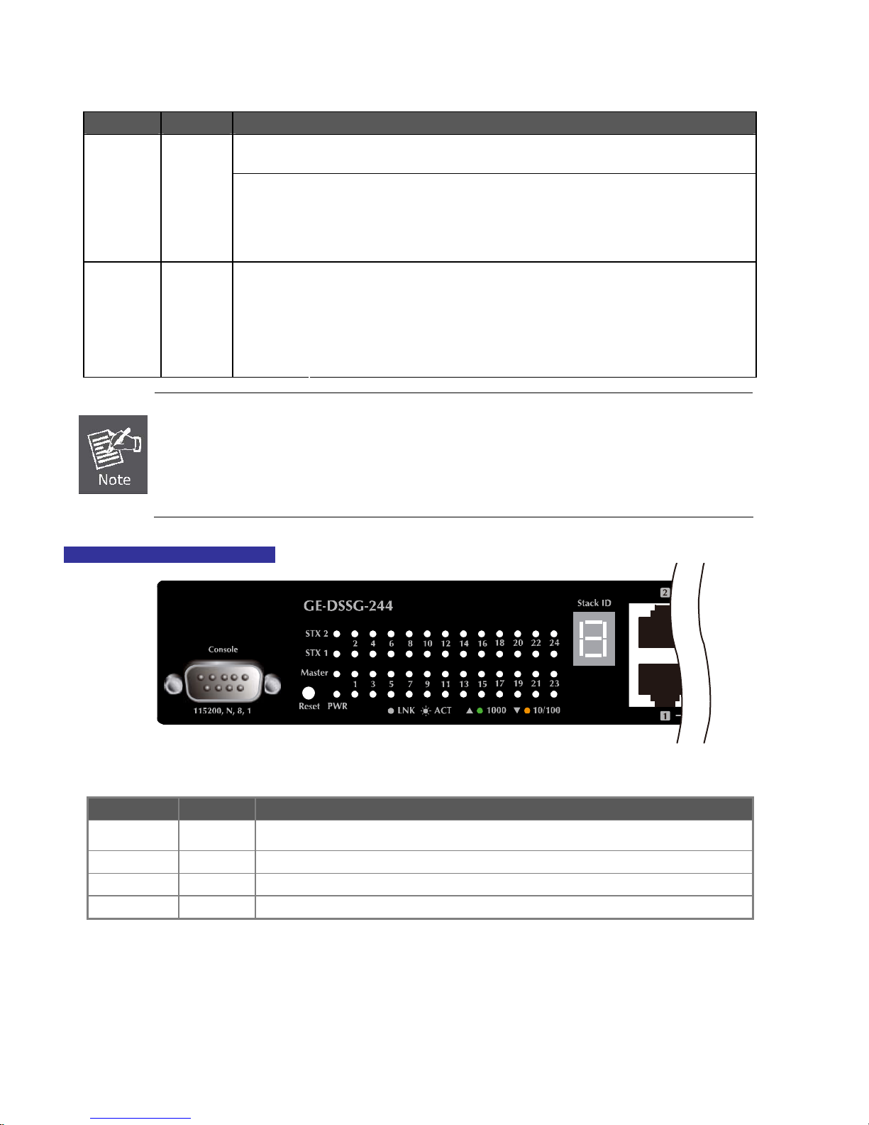
GE-DSSG-244 LED indication
■ System
LED Color Function
PWR Green
Master Green Illuminates to indicate that the Switch is the Master of the stack group
STX1 Green Illuminates to indicate the stacking link through that port is successfully established.
STX2 Green Illuminates to indicate the stacking link through that port is successfully established.
Illuminates to indicate that the Switch is powered on.
Blink to indicate the System is running under booting procedure.
Figure 2-4 GE-DSSG-244 LED panel
21
Page 24
IFS NS3601-24P/4S GE-DSSG-244 and 244-POE User Manual
■ 10/100/1000Base-T interfaces (Shared Port-1~Port-8)
LED Color Function
illuminates:
To indicate the link through that port is successfully established with speed
1000Mbps
1000
LNK/ACT
10/100
LNK/ACT
■ 100 / 1000Base-X SFP interfaces
LED Color Function
1000
LNK
100
LNK/ACT
■ 7-Segment LED Display
Stack ID (1~9, A~F, 0): To indicate the Switch ID of each IFS Managed Switch. Switch IDs are used to uniquely identify the
Managed Switches within a stack. The Switch ID of each Managed Switch is shown on the display on the front of the Managed
Switch and is used widely in the web pages as well as in the CLI commands of the Stack group.
Stack ID 1 2 3 4 5 6 7 8 9 A. B. C. D. E. F. 0
Switch ID 1 2 3 4 5 6 7 8 9 10 11 12 13 14 15 16
Green
Orange
Green
Orange
Blink:
Off:
Illuminates:
Blink:
Off:
Illuminates:
Off:
Illuminates:
Blink:
Off:
To indicate that the switch is actively sending or receiving data over that
port.
If L10/100 NK/ACT LED light-> indicate that the port is operating at 10Mbps
or 100Mbps
If LNK/ACT LED Off -> indicates that the port is link down
To indicate the link through that port is successfully established with speed
10Mbps or 100Mbps
To indicate that the switch is actively sending or receiving data over that
port.
If 1000 LNK/ACT LED light-> indicates that the port is operating at
1000Mbps
If 1000 LNK/ACT LED Off -> indicates that the port is link down
To indicate the link through that SFP port is successfully established with
speed 1000Mbps
To indicate that the SFP port is link down
To indicate the link through that port is successfully established with speed
100Mbps
To indicate that the switch is actively sending or receiving data over that
port.
If 1000 LNK/ACT LED light-> indicate that the port is operating at
1000Mbps
If 1000 LNK/ACT LED Off -> indicate that the port is link down
Switch Rear Panel
The rear panel of the Managed Switch indicates an AC inlet power socket, which works with the input power range from 100 to 240V
AC, 50-60Hz. Figure 2-5 & Figure 2-6 shows the rear panel of these Managed Switches.
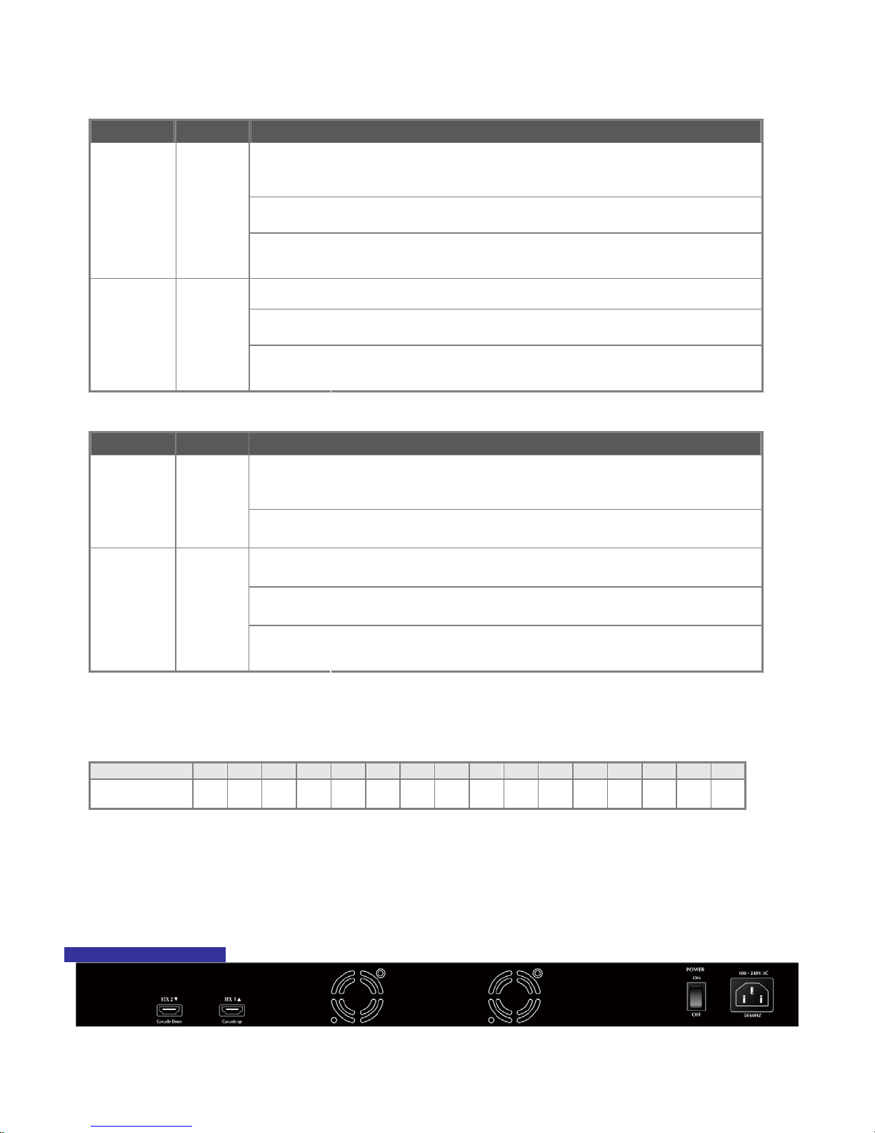
GE-DSSG-244 Rear Panel
Figure 2-5 Rear panel of GE-DSSG-244
22
Page 25
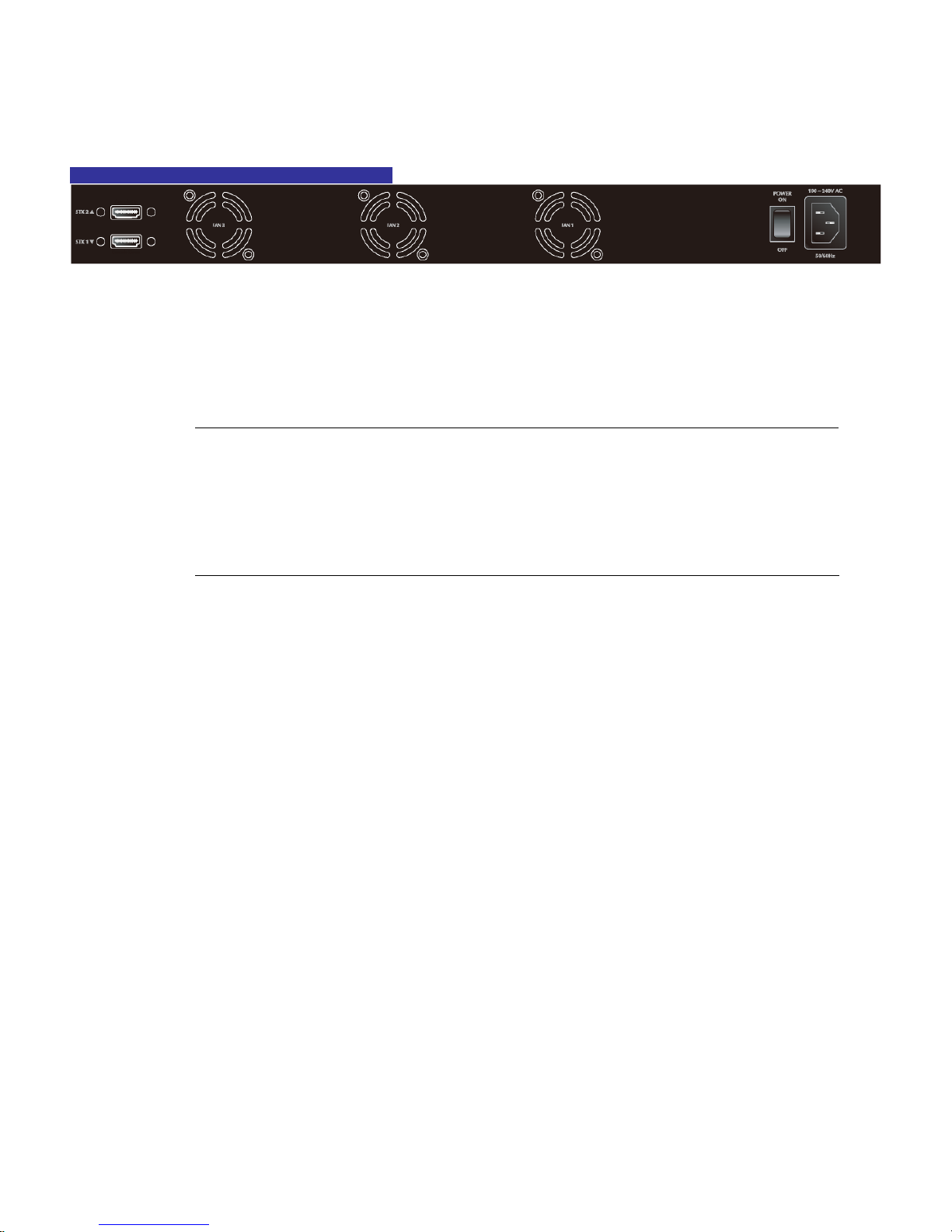
NS3601-24P/4S / GE-DSSG-244-POE Rear Panel
IFS NS3601-24P/4S GE-DSSG-244 and 244-POE User Manual
Figure 2-6 Rear panel of NS3601-24P/4SP and GE-DSSG-244-POE
■ AC Power Receptacle
For compatibility with electric service in most areas of the world, the Managed Switch’s power supply automatically adjusts to
line power in the range 100-240VAC and 50/60 Hz.
Plug the female end of the power cord firmly into the receptalbe on the rear panel of the Managed Switch. Plug the other end of
the power cord into an electric service outlet.
1. The device requires a power connection to operate. If your networks should active all the time,
please consider using UPS (Uninterrupted Power Supply) for your device. It will prevent you from
Power Notice:
network data loss or network downtime.
2. For additional protection against unregulated voltage or current surges, you may also want to
consider surge suppression as part of your installation.
Install the Switch
This section describes how to install your Managed Switch and make connections to the Managed Switch. Please read the following
topics and perform the procedures in the order being presented. To install your Managed Switch on a desktop or shelf, simply
complete the following steps.
Desktop Installation
To install the Managed Switch on desktop or shelf, please follows these steps:
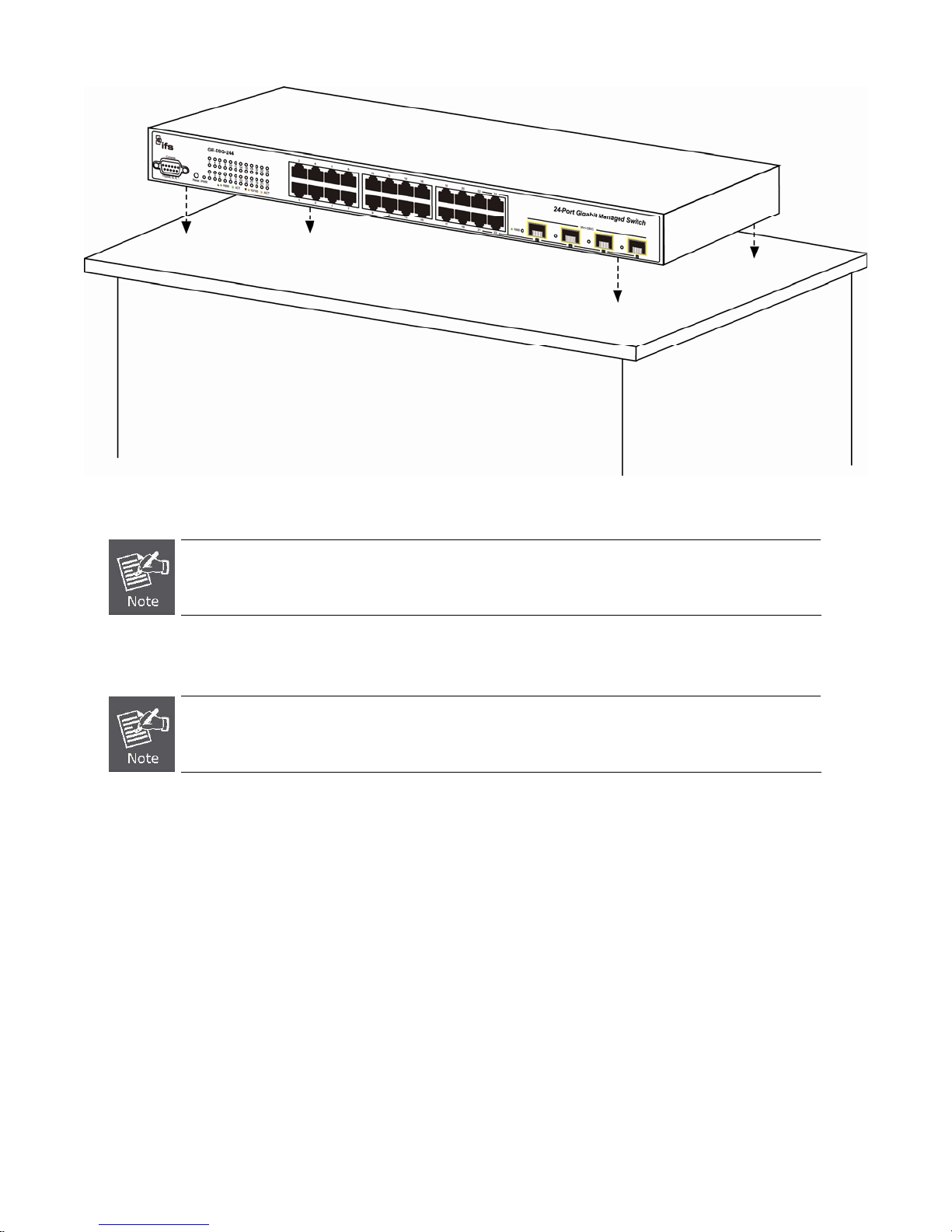
Step1: Attach the rubber feet to the recessed areas on the bottom of the Managed Switch.
Step2: Place the Managed Switch on the desktop or the shelf near an AC power source, as shown in Figure 2-7.
23
Page 26
IFS NS3601-24P/4S GE-DSSG-244 and 244-POE User Manual
Figure 2-7 Place the Managed Switch on the desktop
Step3: Keep enough ventilation space between the Managed Switch and the surrounding objects.
When choosing a location, please keep in mind the environmental restrictions discussed in Chapter 1,
Section 5 Product Specification.
Step4: Connect the Managed Switch to network devices.
Connect one end of a standard network cable to the 10/100/1000 RJ-45 ports on the front of the Managed Switch
Connect the other end of the cable to the network devices such as printer servers, workstations or routers…etc.
Connection to the Managed Switch requires UTP Category 5 network cabling with RJ-45 tips. For more
information, please see the Cabling Specification in Appendix A.
24
Page 27

IFS NS3601-24P/4S GE-DSSG-244 and 244-POE User Manual
Step5: Supply power to the Managed Switch.
Connect one end of the power cable to the Managed Switch.
Connect the power plug of the power cable to a standard wall outlet.
When the Managed Switch receives power, the Power LED should remain solid Green.
Rack Mounting
To install the Managed Switch in a 19-inch standard rack, please follows the instructions described below.
Step1: Place the Managed Switch on a hard flat surface, with the front panel positioned towards the front side.
Step2: Attach the rack-mount bracket to each side of the Managed Switch with supplied screws attached to the package.
Figure 2-8 shows how to attach brackets to one side of the Managed Switch.
Figure 2-8 Attach brackets to the Managed Switch.
You must use the screws supplied with the mounting brackets. Damage caused to the parts by
using incorrect screws would invalidate the warranty.
Step3: Secure the brackets tightly.
Step4: Follow the same steps to attach the second bracket to the opposite side.
Step5: After the brackets are attached to the Managed Switch, use suitable screws to securely attach the brackets to the rack, as
shown in Figure 2-8.
25
Page 28
IFS NS3601-24P/4S GE-DSSG-244 and 244-POE User Manual
Figure 2-8 Mounting IFS-24040 in a Rack
Step6: Proceeds with the steps 4 and steps 5 of session 2.2.1 Desktop Installation to connect the network cabling and supply power
to the Managed Switch.
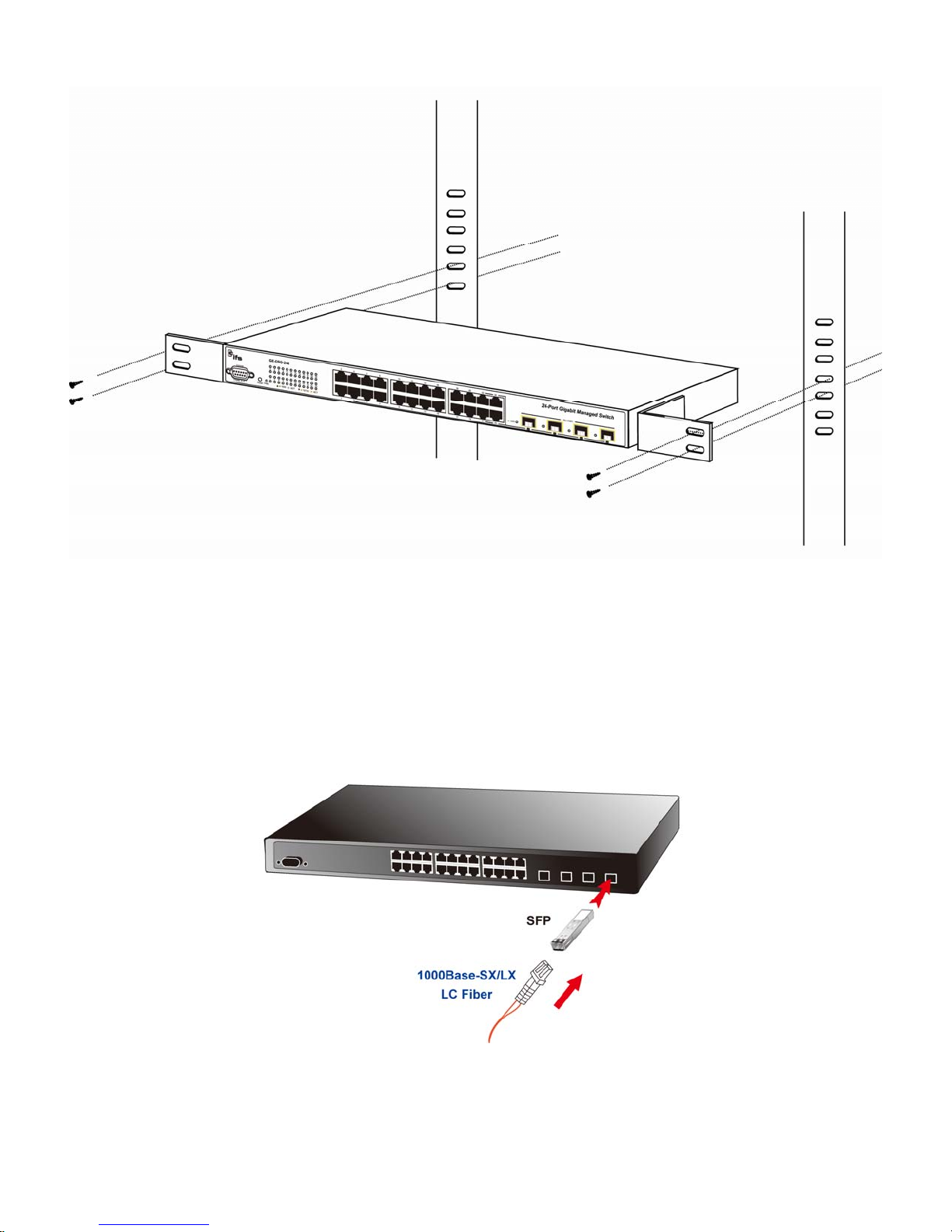
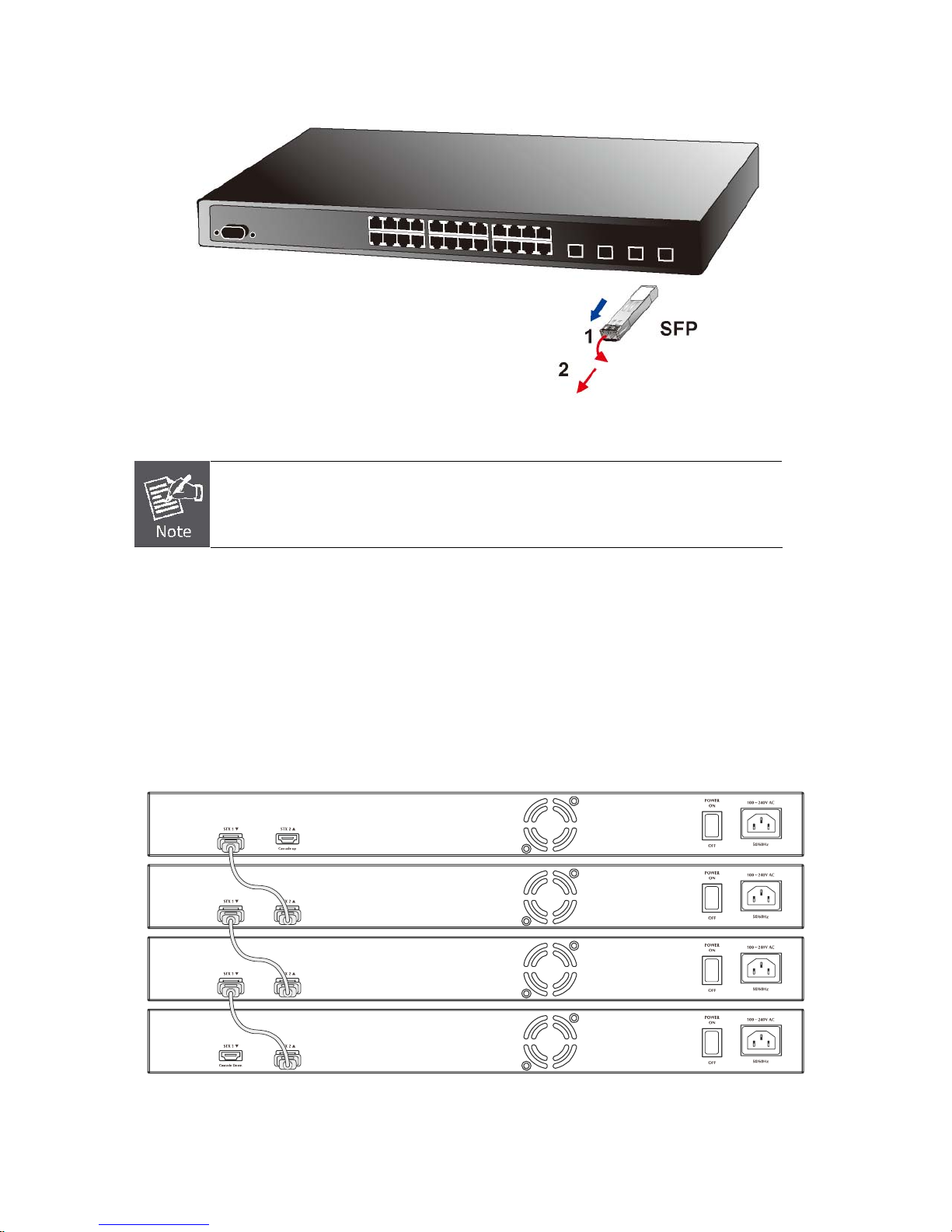
Installing the SFP transceiver
The sections describe how to plug-in an SFP transceiver into an SFP slot.
The SFP transceivers are hot-swappable. You can plug-in and out the transceiver to/from any SFP port without a need to power
down the Managed Switch. As the Figure 2-9.
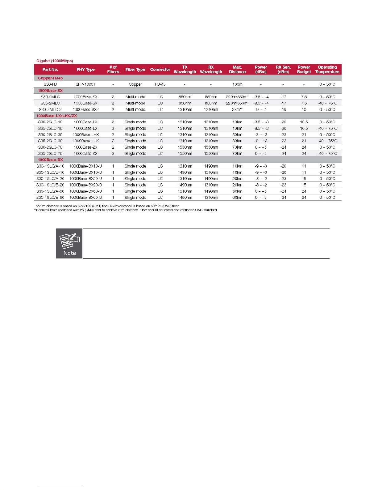
Approved IFS SFP Transceivers
IFS Managed switches supports both single mode and multi mode SFP transceivers. Please refer to below chart, as well as IFS
website for latest compatible SFP modules.
Figure 2-9 Plug-in the SFP transceiver
26
Page 29
1000Base-SX/LX SFP transceiver:
IFS NS3601-24P/4S GE-DSSG-244 and 244-POE User Manual
We recommend using IFS SFPs on the Managed Switch. If you insert a SFP transceiver that is not
supported, the Managed Switch will not recognize it.
Before connecting the other switches, workstation or Media Converter:
1. Make sure both sides use the same SFP transceiver, for example: 1000Base-SX to 1000Base-SX, 1000Base-LX to
1000Base-LX.
2. Make sure the fiber-optic cable type match the SFP transceiver model.
¾ To connect to 1000Base-SX SFP transceiver, use the Multi-mode fiber cable- with one side must be male duplex LC
connector type.
¾ To connect to 1000Base-LX SFP transceiver, use the Single-mode fiber cable-with one side must be male duplex LC
connector type.
Connect the fiber cable
1. Attach the duplex LC connector on the network cable into the SFP transceiver.
2. Connect the other end of the cable to a device – switches with SFP installed, fiber NIC on a workstation or a Media Converter..
3. Check the LNK/ACT LED of the SFP slot on the front of the Managed Switch. Ensure that the SFP transceiver is operating
correctly.
4. Check the Link mode of the SFP port if the link failed.
Remove the transceiver module
1. Make sure there is no network activity by consult or check with the network administrator. Or through the management
interface of the switch/converter (if available) to disable the port in advance.
2. Remove the Fiber Optic Cable gently.
3. Turn the handle of the MGB module to horizontal position.
4. Pull out the module gently with the handle.
27
Page 30
IFS NS3601-24P/4S GE-DSSG-244 and 244-POE User Manual
Figure 2-10 Pull out the SFP transceiver
Never pull out the module without pull the handle or the push bolts on the module. Direct pull
out the module may damage the module and SFP module slot of the Managed Switch.
Stack Installation
IFS NS3601-24P/4S and GE-DSSG Series
The IFS NS3601-24P/4S and GE-DSSG-244 series Managed Switch provides a switch stacking function to manage up to 16
switches using a single IP address. And up to 384 Gigabit Ethernet ports can be managed by a stacking group and you can add
ports and functionality as needed. You can add IFS NS3601-24P/4S and GE-DSSG-244 series switches as needed to support more
network clients, knowing that your switching fabric will scale to meet increasing traffic demands.
Two types of stack topologies are supported by the IFS NS3601-24P/4S and GE-DSSG-244 series:
Chain topology (same as a disconnected ring)
Ring topology
Please find the following picture for sample connection.
Figure 2-11 Chain Stack topology
28
Page 31

IFS NS3601-24P/4S GE-DSSG-244 and 244-POE User Manual
Figure 2-12 Ring Stack topology
Connecting Stacking cable
Before attempting to connect stacking ports, verify that you have the required stack cables. The following cables are used to connect
stacked switches:
• NS-CBL-50: 50cm, Short stack cable –used to connect adjacent IFS switches.
• NS-CBL-200: 200cm, Long / Redundant stack cable – used to connect the top and bottom IFS switches of a stack.
There are two high-performance HDMI-like Stack ports on the rear panel for proprietary management stack. Only these IFS stacking
cables can be used for proper functionality.
STEP-1: Plug one end of the cable in the “STX1 / Cascade Down” port and the other end to the ”STX2 / Cascade UP” port of next
device.
STEP-2: Repeat the step for every device in the stack cluster, then ending at last switch.
STEP-3: If you wish to implement stack redundancy, use the long stack cable NS-CBL-200 to connect the stack port marked “STX1 /
Cascade Down” on the bottom switch to the port marked “STX2 / Cascade Up” on the top switch of the stack.
Figure 2-13 Stacking connection
29
Page 32

IFS NS3601-24P/4S GE-DSSG-244 and 244-POE User Manual
The stack port is for management and data packets to be transmitted between other IFS stackable
switches, the stack ports can’t be configured with Layer 2 features via management interface.
STEP-4: Power up the stack switches.
Management Stacking
The stack operation of the IFS Managed Switch supports Plug and Play Stacking connection and auto stack configuration.
STEP-5: Once the stack start operation, the Stack master be automatically elected without any configuration required. The Stack
master is indicated by a green “Master” LED on the front panel. As the Figure 2-14.
Figure 2-14 Stack Master with “Master” LED lit
STEP-6: When an IFS Switch is added to the stack, a Switch ID is automatically assigned to the new IFS Switch. The automatic SID
assignment can be modified by choosing a different Switch ID on the Stack Configuration page. This method allows Switch
IDs to be assigned so that it is easier for the user to remember the ID of each switch.
STEP-7: Connect the RS-232 serial cable to the console port on the front of the stack master, then loin the IFS Switch to start the
switch management. The default IP address of the IFS Switch is 192.168.0.100.
1. The stack switch with least priority ID or MAC Address number will become Master. Only Master
switch’s management interface (console, telnet, web and SNMP) is accessible.
30
Page 33

IFS NS3601-24P/4S GE-DSSG-244 and 244-POE User Manual
It’s allow to build a stack of up to 16 IFS Switches. If there is the space limitation or power issue and you wish to stack all the
switches in different racks, use long stack cables “NS-CBL-200” to connect two stacks.
2m stack cable NS-CBL-200 2m stack cable NS-CBL-200
Figure 2-15 Separated Stack connection
31
Page 34

IFS NS3601-24P/4S GE-DSSG-244 and 244-POE User Manual
SWITCH MANAGEMENT
This chapter explains the methods that you can use to configure management access to the Managed Switch. It describes the types
of management applications and the communication and management protocols that deliver data between your management
device (workstation or personal computer) and the system. It also contains information about port connection options.
This chapter covers the following topics:
Requirements
Management Access Overview
Administration Console Access
Web Management Access
SNMP Access
Standards, Protocols, and Related Reading
Requirements
Workstations of subscribers running Windows 98/ME, NT4.0, 2000/XP, MAC OS9 or later, Linux, UNIX or other
platform compatible with TCP/IP protocols.
Workstation installed with Ethernet NIC (Network Interface Card)
Serial Port connection (Terminal)
• Above PC with COM Port (DB9 / RS-232) or USB-to-RS-232 converter
Ethernet Port connection
• Network cables - Use standard network (UTP) cables with RJ45 connectors.
Above Workstation installed with WEB Browser and JAVA runtime environment Plug-in
It is recommended to use Internet Explore 7.0 or above to access Managed Switch.
32
Page 35

IFS NS3601-24P/4S GE-DSSG-244 and 244-POE User Manual
Management Access Overview
The Managed Switch gives you the flexibility to access and manage it using any or all of the following methods:
An administration console
Web browser interface
An external SNMP-based network management application
The administration console and Web browser interface support are embedded in the Managed Switch software and are available for
immediate use. Each of these management methods has their own advantages. Table 3-1 compares the three management
methods.
Method Advantages Disadvantages
Console
Web Browser
SNMP Agent
• No IP address or subnet needed
• Text-based
• Telnet functionality and HyperTerminal
built into Windows
95/98/NT/2000/ME/XP operating
systems
• Secure
• Ideal for configuring the switch remotely
• Compatible with all popular browsers
• Can be accessed from any location
• User friendly GUI
• Communicates with switch functions at
the MIB level
• Based on open standards
Table 3-1 Management Methods Comparison
• Must be near switch or use dial-up connection
• Not convenient for remote users
• Modem connection may prove to be unreliable
or slow
• Security can be compromised (hackers need
only know the IP address and subnet mask)
• May encounter lag times on poor connections
• Requires SNMP manager software
• Least visually appealing of all three methods
• Some settings require calculations
• Security can be compromised (hackers need
only know the community name)
Administration Console
The administration console is an internal, character-oriented, and command line user interface for performing system administration
such as displaying statistics or changing option settings. Using this method, you can view the administration console from a terminal,
personal computer, Apple Macintosh, or workstation connected to the switch's console (serial) port.
There are two ways to use this management method: via direct access or modem port access. The following sections describe
these methods. For more information about using the console, refer to Chapter 5 Command Line Interface Console
Management.
Figure 3-1 Console management
Direct Access
Direct access to the administration console is achieved by directly connecting a terminal or a PC equipped with a
terminal-emulation program (such as HyperTerminal) to the Managed Switch console (serial) port.
When using this management method, a straight DB9 RS-232 cable is required to connect the switch to the PC. After making
this connection, configure the terminal-emulation program to use the following parameters:
The default parameters are:
115200 bps
8 data bits
No parity
1 stop bit
33
Page 36

IFS NS3601-24P/4S GE-DSSG-244 and 244-POE User Manual
Figure 3-2 Terminal parameter settings
You can change these settings, if desired, after you log on. This management method is often preferred because you can remain
connected and monitor the system during system reboots. Also, certain error messages are sent to the serial port, regardless of the
interface through which the associated action was initiated. A Macintosh or PC attachment can use any terminal-emulation program
for connecting to the terminal serial port. A workstation attachment under UNIX can use an emulator such as TIP.
Web Management
The Managed Switch offers management features that allow users to manage the Managed Switch from anywhere on the network
through a standard browser such as Microsoft Internet Explorer. After you set up your IP address for the switch, you can access the
Managed Switch's Web interface applications directly in your Web browser by entering the IP address of the Managed Switch.
You can then use your Web browser to list and manage the Managed Switch configuration parameters from one central location, just
as if you were directly connected to the Managed Switch's console port. Web Management requires either Microsoft Internet
Explorer 7.0 or later, Safari or Mozilla Firefox 3.0 or later.
Figure 3-3 Web management
34
Page 37

IFS NS3601-24P/4S GE-DSSG-244 and 244-POE User Manual
Figure 3-4 Web main screen of Managed Switch
SNMP-Based Network Management
You can use an external SNMP-based application to configure and manage the Managed Switch, such as SNMPc Network Manager,
HP Openview Network Node Management (NNM) or What’s Up Gold. This management method requires the SNMP agent on the
switch and the SNMP Network Management Station to use the same community string. This management method, in fact, uses
two community strings: the get community string and the set community string. If the SNMP Net-work management Station only
knows the set community string, it can read and write to the MIBs. However, if it only knows the get community string, it can only
read MIBs. The default gets and sets community strings for the Managed Switch are public.
Figure 3-5 SNMP management
35
Page 38

IFS NS3601-24P/4S GE-DSSG-244 and 244-POE User Manual
36
Page 39

IFS NS3601-24P/4S GE-DSSG-244 and 244-POE User Manual
WEB CONFIGURATION
This section introduces the configuration and functions of the Web-Based management.
About Web-based Management
The Managed Switch offers management features that allow users to manage the Managed Switch from anywhere on the network
through a standard browser such as Microsoft Internet Explorer.
The Web-Based Management supports Internet Explorer 7.0. It is based on Java Applets with an aim to reduce network bandwidth
consumption, enhance access speed and present an easy viewing screen.
By default, IE7.0 or later version does not allow Java Applets to open sockets. The user has to
explicitly modify the browser setting to enable Java Applets to use network ports.
The Managed Switch can be configured through an Ethernet connection, make sure the manager PC must be set on same the IP
subnet address with the Managed Switch.
For example, the default IP address of the IFS Managed Switch is 192.168.0.100, then the manager PC should be set at
192.168.0.x (where x is a number between 1 and 254, except 100), and the default subnet mask is 255.255.255.0.
If you have changed the default IP address of the Managed Switch to 192.168.1.1 with subnet mask 255.255.255.0 via console,
then the manager PC should be set at 192.168.1.x (where x is a number between 2 and 254) to do the relative configuration on
manager PC.
Figure 4-1-1 Web Management
37
Page 40

IFS NS3601-24P/4S GE-DSSG-244 and 244-POE User Manual
Logging on the switch
1. Use Internet Explorer 7.0 or above Web browser. Enter the factory-default IP address to access the Web interface. The
factory-default IP Address as following:
http://192.168.0.100
2. When the following login screen appears, please enter the default username "admin" with password “admin” (or the
username/password you have changed via console) to login the main screen of Managed Switch. The login screen is shown
Figure 4-1-2.
Figure 4-1-2 Login screen
Default User name: admin
Default Password: admin
After entering the username and password, the main screen appears as Figure 4-1-3.
38
Page 41

IFS NS3601-24P/4S GE-DSSG-244 and 244-POE User Manual
Figure 4-1-3 Default main page
Now, you can use the Web management interface to continue the switch management or manage the Managed Switch by Web
interface. The Switch Menu on the left of the web page lets you access all the commands and statistics the Managed Switch
provides.
1. It is recommended to use Internet Explore 7.0 or above to access Managed Switch.
2. Since the changed IP address take effect immediately after you click on the Save button,
you need to use the new IP address to access the Web interface.
3. For security reason, please change and memorize the new password after this first setup.
4. The Switch only accepts command in lowercase letters in the web interface.
39
Page 42

IFS NS3601-24P/4S GE-DSSG-244 and 244-POE User Manual
Main Web Page
The IFS Managed Switch provides a Web-based browser interface for configuring and managing it. This interface allows you to
access the Managed Switch using the Web browser of your choice. This chapter describes how to use the Managed Switch’s Web
browser interface to configure and manage it.
Main Functions Menu
Copper Port Link Status
SFP Port Link Status
Stack Port Link Status
Main Screen
Figure 4-1-4 Main Page
Panel Display
The web agent displays an image of the Managed Switch’s ports. The Mode can be set to display different information for the ports,
including Link up or Link down. Clicking on the image of a port opens the Port Statistics page.
The port states are illustrated as follows:
Main Menu
Using the onboard web agent, you can define system parameters, manage and control the Managed Switch, and all its ports, or
monitor network conditions. Via the Web-Management, the administrator can setup the Managed Switch by select the functions
those listed in the Main Function. The screen is shown Figure 4-1-5.
Help Button
State Disabled Down Link
RJ-45 Ports
SFP Ports
Stack Ports
40
Page 43

IFS NS3601-24P/4S GE-DSSG-244 and 244-POE User Manual
Figure 4-1-5 IFS Managed Switch Main Functions Menu
41
Page 44

IFS NS3601-24P/4S GE-DSSG-244 and 244-POE User Manual
System
Use the System menu items to display and configure basic administrative details of the Managed Switch. Under System the
following topics are provided to configure and view the system information: This section has the following items:
■ System Information The switch system information is provided here.
■ IP Configuration Configure the switch-managed
■ IPv6 Configuration Configure the switch-managed
■ Users Configuration
■ Users Privilege Levels
■ NTP Configuration Configure NTP on this page.
■ UPnP Configure UPnP on this page.
■ DHCP Relay Configure DHCP Relay on this page.
■ DHCP Relay Statistics This page provides statistics for
■ CPU Load This page displays the CPU load, using a SVG graph.
■ System Log The switch system log information is provided here.
■ Detailed Log The switch system detailed log information is provided here.
■ Remote Syslog Configure remote syslog on this page.
■ SMTP Configure Configure SMTP on this page.
■ Web Firmware Upgrade This page facilitates an update of the firmware controlling the switch.
■ TFTP Firmware Upgrade Upgrade the firmware via TFTP server
■ Configuration Backup
■ Configuration Upload
■ Factory Default
■ System Reboot You can restart the stack switch on this page. After restart, the stack switch
This page provides an overview of the current users. Currently the only way
to login as another user on the web server is to close and reopen the
browser.
This page provides an overview of the privilege levels.
You can save the switch configuration. The configuration file is in XML format
with a hierarchy of tags.
You can load the switch configuration. The configuration file is in XML format
with a hierarchy of tags.
You can reset the configuration of the stack switch on this page. Only the
configuration is retained.
will boot normally.
IP information on this page.
IPv6 information on this page.
DHCP relay.
IP
42
Page 45

IFS NS3601-24P/4S GE-DSSG-244 and 244-POE User Manual
System Information
The System Info page provides information for the current device information. System Info page helps a switch administrator to
identify the hardware MAC address, software version and system uptime. The screen is shown Figure 4-2-1.
The page includes the following fields:
Object Description
• Contact
• Name
• Location
• MAC A ddr es s
• Power Status
• T e mperature
• System Date
• System Uptime
• Swithc ID
• Software Version
Figure 4-2-1 System Information page screenshot
The system contact configured in Configuration | System | Information | System
Contact.
The system name configured in Configuration | System | Information | System
Name.
The system location configured in Configuration | System | Information | System
Location.
The MAC Address of this switch.
Indicate AC / DC power supply input of this switch.
Indicate main chipset temperature.
The current (GMT) system time and date. The system time is obtained through
the configured
The period of time the device has been operational.
The switch ID.
The software version of the switch.
SNTP Server, if any.
Buttons
Auto-refresh
: Check this box to enable an automatic refresh of the page at regular intervals.
43
Page 46

IFS NS3601-24P/4S GE-DSSG-244 and 244-POE User Manual
: Click to refresh the page; any changes made locally will be undone.
IP Configuration
The IP Configuration includes the IP Address, Subnet Mask and Gateway. The Configured column is used to view or change the IP
configuration. Fill up the IP Address, Subnet Mask and Gateway for the device. The screen is shown Figure 4-2-2.
Figure 4-2-2 IP Configuration page screenshot
The Current column is used to show the active IP configuration.
Object Description
• DHCP Client
• IP Address
• IP Mask
• IP Router
• VLAN ID
• DNS Server
• DNS Proxy
Buttons
Enable the DHCP client by checking this box. If DHCP fails and the configured IP
address is zero, DHCP will retry. If DHCP fails and the configured IP address is
non-zero, DHCP will stop and the configured IP settings will be used. The DHCP
client will announce the configured System Name as hostname to provide DNS
lookup.
Provide the IP address of this switch in dotted decimal notation.
Provide the IP mask of this switch dotted decimal notation.
Provide the IP address of the router in
Provide the managed VLAN ID. The allowed range is 1 through 4095.
Provide the IP address of the DNS Server in
When DNS proxy is enabled, DUT will relay DNS requests to the current
configured DNS server on DUT, and reply as a DNS resolver to the client device
on the network.
dotted decimal notation.
dotted decimal notation.
: Click to save changes.
: Click to undo any changes made locally and revert to previously saved values.
44
Page 47

IFS NS3601-24P/4S GE-DSSG-244 and 244-POE User Manual
: Click to undo any changes made locally and revert to previously saved values.
IPv6 Configuration
Configure the switch-managed IPv6 information on this page.
The Configured column is used to view or change the IPv6 configuration. The Current column is used to show the active IPv6
configuration. The screen is shown Figure 4-2-3.
The page includes the following fields:
Object Description
• Auto Configuration
• Address
• Prefix
• Router
• VLAN ID
Figure 4-2-3 IPv6 Configuration page screenshot
Enable IPv6 auto-configuration by checking this box. If fails, the configured IPv6
address is zero. The router may delay responding to a router solicitation for a few
seconds, the total time needed to complete auto-configuration can be
significantly longer.
Provide the IPv6 address of this switch. IPv6 address is in 128-bit records
represented as eight fields of up to four hexadecimal digits with a colon
separates each field (:). For example, 'fe80::215:c5ff:fe03:4dc7'. The symbol '::' is
a special syntax that can be used as a shorthand way of representing multiple
16-bit groups of contiguous zeros; but it can only appear once. It also used a
following legally IPv4 address. For example, '::192.1.2.34'.
Provide the IPv6 Prefix of this switch. The allowed range is 1 through 128.
Provide the IPv6 gateway address of this switch. IPv6 address is in 128-bit
records represented as eight fields of up to four hexadecimal digits with a colon
separates each field (:). For example, 'fe80::215:c5ff:fe03:4dc7'. The symbol '::' is
a special syntax that can be used as a shorthand way of representing multiple
16-bit groups of contiguous zeros; but it can only appear once. It also used a
following legally IPv4 address. For example, '::192.1.2.34'.
Provide the IPv6 SNTP Server address of this switch. IPv6 address is in 128-bit
records represented as eight fields of up to four hexadecimal digits with a colon
separates each field (:). For example, 'fe80::215:c5ff:fe03:4dc7'. The symbol '::' is
a special syntax that can be used as a shorthand way of representing multiple
16-bit groups of contiguous zeros; but it can only appear once. It also used a
following legally IPv4 address. For example, '::192.1.2.34'.
Provide the managed VLAN ID. The allowed range is 1 through 4095
Buttons
: Click to save changes.
: Click to undo any changes made locally and revert to previously saved values.
45
Page 48

IFS NS3601-24P/4S GE-DSSG-244 and 244-POE User Manual
Users Configuration
It is allowed to configure the Managed Switch to authenticate users logging into the system for management access using local or
remote authentication methods, such as telnet and Web browser. This Managed Switch provides secure network management
access using the following options:
Local user name and Privilege Level control
Remote Authentication Dial-in User Service (RADIUS)
Terminal Access Controller Access Control System Plus (TACACS+)
This User Configuration page provides an overview of the current local users. The latest UTC Managed Switch provides totally six
different security levels in 3 groups for local user management.
Group Privilege / Security Level Access
Master
IT
Security
Currently the only way to login as another user on the web server is to close and reopen the browser. After setup completed, please
press “Save” button to take effect. Please login web interface with new user name and password, the screen is shown Figure 4-2-4.
Master Admin
Master Viewer
IT Admin
IT Viewer
Security Admin
Security Viewer
Refer to Appendix C
Figure 4-2-4 Users Configuration page screenshot
The page includes the following fields:
Object Description
• Username
• Privilege Level
Buttons
: Click to add a new user.
Add / Edit User
This page configures a user – add, edit or delete user.
The name identifying the user. This is also a link to Edit exist User.
Maximum length: 32 characters;
Maximum number of users: 16
Defaults: admin, and guest
The privilege / Security level for the user.
46
Page 49

IFS NS3601-24P/4S GE-DSSG-244 and 244-POE User Manual
Figure 4-2-5 Add / Edit User Configuration page screenshot
The page includes the following fields:
Object Description
• Username
• Password
• Password (again)
• Privilege Level
Buttons
: Click to save changes.
: Click to undo any changes made locally and revert to previously saved values.
The name identifying the user.
The password of the user.
Confirm the password of the user.
Specifies the privilege level for the user.
Options:
Master Admin
Master Viewer
IT Admin
IT Viewer
Security Admin
Security Viewer
: Click to undo any changes made locally and return to the Users.
: Delete the current user. This button is not available for new configurations (Add new user)
Once the new user is added, the new user entry shown in the Users Configuration page.
47
Page 50

IFS NS3601-24P/4S GE-DSSG-244 and 244-POE User Manual
Figure 4-2-6 User Configuration page screenshot
After change the default password, if you forget the password, press the “Reset” button in the
front panel of the Managed Switch over 10 seconds and then release. The current settings
includeing the VLAN, will be lost and the Managed Switch will restore to factory default.
48
Page 51

IFS NS3601-24P/4S GE-DSSG-244 and 244-POE User Manual
Users Privilege Levels
In addition to the local user account management as configured in “User Configuration”, the Managed Switch allowed to use a
remote access authentication server based on RADIUS or TACACS+ protocols.
This page provides an overview of the privilege levels for remote user account. After setup completed, please press “Save” button
to take effect. Please login web interface with new user name and password, the screen is shown Figure 4-2-7.
Figure 4-2-7 Privilege Levels Configuration page screenshot
49
Page 52

The page includes the following fields:
Object Description
• Group Name
• Privilege Level
Buttons
IFS NS3601-24P/4S GE-DSSG-244 and 244-POE User Manual
The name identifying the privilege group. In most cases, a privilege level group
consists of a single module (e.g. LACP, RSTP or QoS), but a few of them
contains more than one. The following description defines these privilege level
groups in details:
System: Contact, Name, Location, Timezone, Log.
Security: Authentication, System Access Management, Port
(contains Dot1x port, MAC based and the MAC Address Limit), ACL,
HTTPS, SSH, ARP Inspection and IP source guard.
IP: Everything except 'ping'.
Port: Everything except 'VeriPHY'.
Diagnostics: 'ping' and 'VeriPHY'.
Maintenance: CLI- System Reboot, System Restore Default,
System Password, Configuration Save, Configuration Load and
Firmware Load. Web- Users, Privilege Levels and everything in
Maintenance.
Every privilege level group has an authorization level for the following sub
groups:
Configuration read-only
Configuration/execute read-write
Status/statistics read-only
Status/statistics read-write (e.g. for clearing of statistics).
: Click to save changes.
: Click to undo any changes made locally and revert to previously saved values.
50
Page 53

IFS NS3601-24P/4S GE-DSSG-244 and 244-POE User Manual
NTP Configuration
Configure NTP on this page.
NTP is an acronym for Network Time Protocol, a network protocol for synchronizing the clocks of computer systems. NTP uses
UDP (data grams) as transport layer. You can specify NTP Servers and set GMT Time zone. The NTP Configuration screen is
shown Figure 4-2-8.
The page includes the following fields:
Object Description
• Mode
• Timezone
• Server #
Buttons
: Click to save changes.
: Click to undo any changes made locally and revert to previously saved values.
UPnP Configuration
Figure 4-2-8 NTP
Indicates the NTP mode operation. Possible modes are:
Enabled: Enable NTP mode operation. When enable NTP mode operation, the
agent forward and to transfer NTP messages between the clients and the server
when they are not on the same subnet domain.
Disabled: Disable NTP mode operation.
Allow select the time zone according to current location of switch.
Provide the NTP IPv4 or IPv6 address of this switch. IPv6 address is in 128-bit
records represented as eight fields of up to four hexadecimal digits with a colon
separates each field (:). For example, 'fe80::215:c5ff:fe03:4dc7'. The symbol '::' is
a special syntax that can be used as a shorthand way of representing multiple
16-bit groups of contiguous zeros; but it can only appear once. It also used a
following legally IPv4 address. For example, '::192.1.2.34'.
Configuration page screenshot
Configure UPnP on this page.
UPnP is an acronym for Universal Plug and Play. The goals of UPnP are to allow devices to connect seamlessly and to simplify the
implementation of networks in the home (data sharing, communications, and entertainment) and in corporate environments for
simplified installation of computer components. The UPnP Configuration screen is shown Figure 4-2-9.
51
Page 54

IFS NS3601-24P/4S GE-DSSG-244 and 244-POE User Manual
The page includes the following fields:
Object Description
• Mode
• TTL
• Advertising Duration
Figure 4-2-9 UPnP
Indicates the UPnP operation mode. Possible modes are:
Enabled: Enable UPnP mode operation.
Disabled: Disable UPnP mode operation.
When the mode is enabled, two ACEs are added automatically to trap UPNP
related packets to CPU. The ACEs are automatically removed when the mode is
disabled.
The TTL value is used by UPnP to send SSDP advertisement messages. Valid
values are in the range 1 to 255.
The duration, carried in SSDP packets, is used to inform a control point or control
points how often it or they should receive a SSDP advertisement message from
this switch. If a control point does not receive any message within the duration, it
will think that the switch no longer exists. Due to the unreliable nature of
the standard it is recommended that such refreshing of advertisements to be
done at less than one-half of the advertising duration. In the implementation, the
switch sends SSDP messages periodically at the interval one-half of the
advertising duration minus 30 seconds. Valid values are in the range 100 to
86400.
Configuration page screenshot
UDP, in
52
Page 55

Buttons
IFS NS3601-24P/4S GE-DSSG-244 and 244-POE User Manual
: Click to save changes.
: Click to undo any changes made locally and revert to previously saved values.
Figure 4-2-10 UPnP devices shows on Windows My Network Places
DHCP Relay
Configure DHCP Relay on this page. DHCP Relay is used to forward and to transfer DHCP messages between the clients and the
server when they are not on the same subnet domain.
The DHCP option 82 enables a DHCP relay agent to insert specific information into a DHCP request packets when forwarding client
DHCP packets to a DHCP server and remove the specific information from a DHCP reply packets when forwarding server DHCP
packets to a DHCP client. The DHCP server can use this information to implement IP address or other assignment policies.
Specifically the option works by setting two sub-options:
Circuit ID (option 1)
Remote ID (option2).
The Circuit ID sub-option is supposed to include information specific to which circuit the request came in on.
The Remote ID sub-option was designed to carry information relating to the remote host end of the circuit.
The definition of Circuit ID in the switch is 4 bytes in length and the format is "vlan_id" "module_id" "port_no". The parameter of
"vlan_id" is the first two bytes represent the VLAN ID. The parameter of "module_id" is the third byte for the module ID (in
standalone switch it always equal 0, in stackable switch it means switch ID). The parameter of "port_no" is the fourth byte and it
means the port number.
The Remote ID is 6 bytes in length, and the value is equal the DHCP relay agent’s MAC address. The DHCP Relay Configuration
screen is shown Figure 4-2-11.
53
Page 56

IFS NS3601-24P/4S GE-DSSG-244 and 244-POE User Manual
Figure 4-2-11 DHCP Relay
The page includes the following fields:
Object Description
• Relay Mode
• Relay Server
• Relay Information
Mode
• Relay Information
Policy
Buttons
Configuration page screenshot
Indicates the DHCP relay mode operation. Possible modes are:
Enabled: Enable DHCP relay mode operation. When enable DHCP relay mode
operation, the agent forward and to transfer DHCP messages between the
clients and the server when they are not on the same subnet domain. And the
DHCP broadcast message won't flood for security considered.
Disabled: Disable DHCP relay mode operation.
Indicates the DHCP relay server IP address. A DHCP relay agent is used to
forward and to transfer DHCP messages between the clients and the server
when they are not on the same subnet domain.
Indicates the DHCP relay information mode option operation. Possible modes
are:
Enabled: Enable DHCP relay information mode operation. When enable DHCP
relay information mode operation, the agent insert specific information (option
82) into a DHCP message when forwarding to DHCP server and remove it from a
DHCP message when transferring to DHCP client. It only works under DHCP
relay operation mode enabled.
Disabled: Disable DHCP relay information mode operation.
Indicates the DHCP relay information option policy. When enable DHCP relay
information mode operation, if agent receive a DHCP message that already
contains relay agent information. It will enforce the policy. And it only works under
DHCP relay information operation mode enabled. Possible policies are:
Replace: Replace the original relay information when receive a DHCP message
that already contains it.
Keep: Keep the original relay information when receive a DHCP message that
already contains it.
Drop: Drop the package when receive a DHCP message that already contains
relay information.
: Click to save changes.
: Click to undo any changes made locally and revert to previously saved values.
54
Page 57

IFS NS3601-24P/4S GE-DSSG-244 and 244-POE User Manual
DHCP Relay Statistics
This page provides statistics for DHCP relay. The DHCP Relay Statistics screen is shown Figure 4-2-12.
The page includes the following fields:
Server Statistics
Object Description
• Transmit to Server
• Transmit Error
• Receive form Server
• Receive Missing Agent
Option
• Receive Missing
Circuit ID
• Receive Missing
Remote ID
• Receive Bad Circuit ID
• Receive Bad Remote
ID
Client Statistics
Object Description
• Transmit to Client
Figure 4-2-12 DHCP Relay
The packets number that relayed from client to server.
The packets number that errors sending packets to clients.
The packets number that received packets from server.
The packets number that received packets without agent information options.
The packets number that received packets which the Circuit ID option was
missing.
The packets number that received packets which Remote ID option was missing.
The packets number that the Circuit ID option did not match known circuit ID.
The packets number that the Remote ID option did not match known Remote ID.
The number of packets relayed from server to client.
Statistics page screenshot
• Transmit Error
• Receive form Client
• Receive Agent Option
• Replace Agent Option
• Keep Agent Optin
• Drop Agent Option
The number of packets that sent errors while sending packets to servers.
The number of packets received packets from server.
The number of packets that received packets with relay agent information option.
The number of packets that replaced received packets with relay agent
information option.
The number of packets that keepped received packets with relay agent
information option.
The number of packets that dropped received packets with relay agent
information option.
55
Page 58

IFS NS3601-24P/4S GE-DSSG-244 and 244-POE User Manual
Buttons
Auto-refresh
: Check this box to enable an automatic refresh of the page at regular intervals.
: Click to refresh the page; any changes made locally will be undone.
: Clear all statistics.
CPU Load
This page displays the CPU load, using a SVG graph.
The load is measured as averaged over the last 100ms, 1sec and 10 seconds intervals. The last 120 samles are graphed, and the
last numbers are displayed as text as well.
In order to display the SVG graph, your browser must support the SVG format. Consult the
browser support. Specifically, at the time of writing, Microsoft Internet Explorer will need to have a plugin installed to support SVG.
The CPU Load screen is shown Figure 4-2-13.
SVG Wiki for more information on
Buttons
Auto-refresh
Figure 4-2-13 CPU Load page screenshot
: Check this box to enable an automatic refresh of the page at regular intervals.
If your browser can not display this chart, please download the Adobe SVG tool and install it in
your computer.
56
Page 59

IFS NS3601-24P/4S GE-DSSG-244 and 244-POE User Manual
System Log
The switch system log information is provided here. The System Log screen is shown Figure 4-2-14.
The page includes the following fields:
Object Description
• ID
• Level
• Time
• Message
Buttons
Auto-refresh
: Hide the statistics.
: Check this box to enable an automatic refresh of the page at regular intervals.
: Click to refresh the page; any changes made locally will be undone.
: Clear all statistics.
Figure 4-2-14 System Log page screenshot
The ID (>= 1) of the system log entry.
The level of the system log entry. The following level types are supported:
Info: Information level of the system log.
Warning: Warning level of the system log.
Error: Error level of the system log.
All: All levels.
The time of the system log entry.
The message of the system log entry.
: Download the statistics.
: Updates the system log entries, starting from the first available entry ID.
: Updates the system log entries, ending at the last entry currently displayed.
: Updates the system log entries, starting from the last entry currently displayed.
: Updates the system log entries, ending at the last available entry ID.
57
Page 60

IFS NS3601-24P/4S GE-DSSG-244 and 244-POE User Manual
Detailed Log
The switch system detailed log information is provided here. The Detailed Log screen is shown Figure 4-2-15.
Figure 4-2-15 Detailed Log page screenshot
The page includs the following fields:
Object Description
• ID
• Message
Buttons
: Download the statistics.
: Click to refresh the page; any changes made locally will be undone.
: Updates the system log entries, starting from the first available entry ID.
: Updates the system log entries, ending at the last entry currently displayed.
: Updates the system log entries, starting from the last entry currently displayed.
: Updates the system log entries, ending at the last available entry ID.
: Print out the system log information.
The ID (>= 1) of the system log entry.
The message of the system log entry.
Remote Syslog
Configure remote syslog on this page. The Remote Syslog screen is shown Figure 4-2-16.
58
Page 61

IFS NS3601-24P/4S GE-DSSG-244 and 244-POE User Manual
The page includes the following fields:
Object Description
• Mode
• Syslog Server IP
Buttons
: Click to save changes.
: Click to undo any changes made locally and revert to previously saved value.
Figure 4-2-16 Remote Syslog page screenshot
Indicates the remote syslog mode operation. Possible modes are:
Enabled: Enable remote syslog mode operation.
Disabled: Disable remote syslog mode operation.
Fill in your remote syslog server IP address.
59
Page 62

IFS NS3601-24P/4S GE-DSSG-244 and 244-POE User Manual
SMTP Configure
This page facilitates a SMTP Configure the switch. The SMTP Configure screen is shown Figure 4-2-17.
The page includes the following fields:
Object Description
• SMTP Mode
• SMTP Server
• SMTP Port
• SMTP Authentication
• Authentication User
Name
• Authentication
Password
• E-mail From
• E-mail Subject
• E-mail 1 To
• E-mail 2 To
Figure 4-2-17 SMTP Configuration page screenshot
Controls whether SMTP is enabled on this switch.
Type the SMTP server name or the IP address of the SMTP server.
Set port number of SMTP service.
Controls whether SMTP authentication is enabled If authentication is required
when an e-mail is sent.
Type the user name for the SMTP server if Authentication is Enable.
Type the password for the SMTP server if Authentication is Enable.
Type the sender’s E-mail address. This address is used for reply e-mails.
Type the subject/title of the e-mail.
Type the receiver’s e-mail address.
60
Page 63

IFS NS3601-24P/4S GE-DSSG-244 and 244-POE User Manual
Buttons
: Send a test mail to mail server to check this account is available or not.
: Click to save changes.
: Click to undo any changes made locally and revert to previously saved values.
Web Firmware Upgrade
This page facilitates an update of the firmware controlling the switch. The Web Firmware Upgrade screen is shown Figure 4-2-18.
Figure 4-2-18 Web Firmware Upgrade page screenshot
To open Firmware Upgrade screen perform the folling:
1. Click System -> Web Firmware Upgrade.
2. The Firmware Upgrade screen is displayed as in Figure 4-2-18.
3. Click the “
4. Select the firmware file and then click “
5. Once the software is loaded to the system successfully, the following screen. The system will load the new software after
reboot.
“button of the main page, the system would pop up the file selection menu to choose firmware.
”, the Software Upload Progress would show the file upload status.
Figure 4-2-19 Software successfully loaded notice screen
DO NOT Power OFF the Managed Switch until the update progress is complete.
Do not quit the Firmware Upgrade page without pressing the “OK” button - after the image
be loaded. Or the system won’t apply the new firmware. User has to repeat the firmware
upgrade processes again.
61
Page 64

IFS NS3601-24P/4S GE-DSSG-244 and 244-POE User Manual
TFTP Firmware Upgrade
The Firmware Upgrade page provides the functions to allow a user to update the Managed Switch firmware from the TFTP server
in the network. Before updating, make sure you have your TFTP server ready and the firmware image is on the TFTP server. The
TFTP Firmware Upgrade screen is shown Figure 4-2-20.
The page includes the following fields:
Object Description
• TFTP Server IP
• Firmware File Name
Buttons
: Click to upgrade firmware.
DO NOT Power OFF the Managed Switch until the update progress is complete.
Do not quit the Firmware Upgrade page without press the “OK” button - after the image be
loaded. Or the system won’t apply the new firmware. User has to repeat the firmware
upgrade processes again.
Figure 4-2-20 TFTP Firmware Update page screenshot
Fill in your TFTP server IP address.
The name of firmware image.
(Maximum length : 24 characters)
Configuration Backup
This function allows backup and reload the current configuration of the Managed Switch to the local management station. The
Configuration Backup screen is shown Figure 4-2-21.
Figure 4-2-21 Configuration Backup page screenshot
You can save/view or load the switch configuration. The configuration file is in XML format with a hierarchy of tags:
Header tags:
Section tags:
<?xml version="1.0"?> and <configuration>. These tags are mandatory and must be
present at the beginning of the file.
<platform>, <global> and <switch>. The platform section must be the first section tag
62
Page 65

IFS NS3601-24P/4S GE-DSSG-244 and 244-POE User Manual
and this section must include the correct platform ID and version. The global section is
optional and includes configuration which is not related to specific switch ports. The
switch section is optional and includes configuration which is related to specific switch
ports.
Module tags:
Group tags:
Parameter
tags:
Configuration parameters are represented as attribute values. When saving the configuration from the switch, the entire
configuration including syntax descriptions is included in the file. The file may then be modified using an editor and loaded to a
switch.
The examples below shows a small configuration file only including configuration of the MAC address age time and the learning
mode per port. When loading this file, only the included parameters will be changed. This means that the age time will be set to 200
and the learn mode will be set to automatic.
Save Configuration
1. Press the “Save Configuration” button to save the current configuration in manager workstation. The following screens in
Figure 4-2-22 & 4-2-23 appear
<ip>, <mac>, <port> etc. These tags identify a module controlling specific parts of the
configuration.
<port_table>, <vlan_table> etc. These tags identify a group of parameters, typically a
table.
<mode>, <entry> etc. These tags identify parameters for the specific section, module
and group. The <entry> tag is used for table entries.
2. Chose the file save path in management workstation.
Figure 4-2-22 File Download screen
63
Page 66

IFS NS3601-24P/4S GE-DSSG-244 and 244-POE User Manual
Figure 4-2-23 File save screen
Configuration Upload
This function allows backup and reload the current configuration of the Managed Switch to the local management station. The
Configuration Upload screen is shown Figure 4-2-24.
Figure 4-2-24 Configuration Upload page screenshot
Configuration Upload
1. Click the “ ” button of the main page, the system would pop up the file selection menu to choose saved configuration.
64
Page 67

IFS NS3601-24P/4S GE-DSSG-244 and 244-POE User Manual
Figure 4-2-25 Windows file selection menu popup
2. Select on the configuration file then click “
3. After the upload process is complete, the main screen displays “Transfer Completed”.
”, the bottom of the browser shows the upload status.
65
Page 68

IFS NS3601-24P/4S GE-DSSG-244 and 244-POE User Manual
Factory Default
You can reset the configuration of the stack switch on this page. Only the IP configuration is retained. The new configuration is
available immediately, which means that no restart is necessary. The Factory Default screen is shown Figure 4-2-26.
Figure 4-2-26 Factory Default page screenshot
Buttons
: Click to reset the configuration to Factory Defaults.
: Click to return to the Port State page without resetting the configuration.
After the “Reset” button is pressed and the device is rebooted, the system will load the default IP settings as following:
。 Default IP address: 192.168.0.100
。 Subnet mask: 255.255.255.0
。 Default Gateway: 192.168.0.254
。 The other setting value is back to disable or none.
To reset the Managed Switch to the Factory default setting, you can also press the hardware reset button
at the front panel about 10 seconds. After the device be rebooted. You can login the management WEB
interface within the same subnet of 192.168.0.xx.
Hardware Reset button
66
Page 69

IFS NS3601-24P/4S GE-DSSG-244 and 244-POE User Manual
System Reboot
The Reboot page enables the device to be rebooted from a remote location. Once the Reboot button is pressed, user have to
re-login the WEB interface about 60 seconds later. The System Reboot screen is shown in Figure 4-2-27.
Figure 4-2-27 System Reboot page screenshot
Buttons
: Click to reboot the system.
: Click to return to the Port State page without reboot the system.
Simple Network Management Protocol
SNMP Overview
The Simple Network Management Protocol (SNMP) is an application layer protocol that facilitates the exchange of management
information between network devices. It is part of the Transmission Control Protocol/Internet Protocol (TCP/IP) protocol suite. SNMP
enables network administrators to manage network performance, find and solve network problems, and plan for network growth.
An SNMP-managed network consists of three key components: Network management stations (NMSs), SNMP agents,
Management information base (MIB) and network-management protocol:
。 Network management stations (NMSs):Sometimes called consoles, these devices execute management applications that
monitor and control network elements. Physically, NMSs are usually engineering workstation-caliber computers with fast
CPUs, megapixel color displays, substantial memory, and abundant disk space. At least one NMS must be present in each
managed environment.
。 Agents:Agents are software modules that reside in network elements. They collect and store management information such
as the number of error packets received by a network element.
。 Management information base (MIB):A MIB is a collection of managed objects residing in a virtual information store.
Collections of related managed objects are defined in specific MIB modules.
。 Network-management protocol: A management protocol is used to convey management information between agents and
NMSs. SNMP is the Internet community's de facto standard management protocol.
SNMP Operations
SNMP itself is a simple request/response protocol. NMSs can send multiple requests without receiving a response.
。 Get -- Allows the NMS to retrieve an object instance from the agent.
。 Set -- Allows the NMS to set values for object instances within an agent.
。 Tra p -- Used by the agent to asynchronously inform the NMS of some event. The SNMPv2 trap message is designed to
replace the SNMPv1 trap message.
SNMP community
An SNMP community is the group that devices and management stations running SNMP belong to. It helps define where information
is sent. The community name is used to identify the group. A SNMP device or agent may belong to more than one SNMP community.
It will not respond to requests from management stations that do not belong to one of its communities. SNMP default communities
are:
。 Write = private
。 Read = public
Use the SNMP Menu to display or configure the Managed Switch's SNMP function. This section has the following items:
System Configuration
Configure SNMP on this page.
67
Page 70

IFS NS3601-24P/4S GE-DSSG-244 and 244-POE User Manual
System Information
Trap Configuration
SNMPv3 Communities
SNMPv3 Users
SNMPv3 Groups
SNMPv3 Views
SNMPv3 Accesses
The system information is provides here.
Configure SNMP trap on this page.
Configure SNMPv3 communities table on this page.
Configure SNMPv3 users table on this page.
Configure SNMPv3 groups table on this page.
Configure SNMPv3 views table on this page.
Configure SNMPv3 accesses table on this page.
SNMP System Configuration
Configure SNMP on this page. The SNMP System Configuration screen is shown Figure 4-3-1.
Figure 4-3-1 SNMP System Configuration page screenshot
The page includes the following fields:
Object Description
• Mode
• Version
• Read Community
• Write Community
• Engine ID
Buttons
Indicates the SNMP mode operation. Possible modes are:
Enabled: Enable SNMP mode operation.
Disabled: Disable SNMP mode operation.
Indicates the SNMP supported version. Possible versions are:
SNMP v1: Set SNMP supported version 1.
SNMP v2c: Set SNMP supported version 2c.
SNMP v3: Set SNMP supported version 3.
Indicates the community read access string to permit access to SNMP agent.
The allowed string length is 0 to 255, and the allowed content is the ASCII
characters from 33 to 126. The field only suits to SNMPv1 and SNMPv2c.
SNMPv3 is using USM for authentication and privacy and the community string
will associated with SNMPv3 communities table.
Indicates the community write access string to permit access to SNMP agent.
The allowed string length is 0 to 255, and the allowed content is the ASCII
characters from 33 to 126. The field only suits to SNMPv1 and SNMPv2c.
SNMPv3 is using USM for authentication and privacy and the community string
will associated with SNMPv3 communities table.
Indicates the SNMPv3 engine ID. The string must contain an even number
between 10 and 64 hexadecimal digits, but all-zeros and all-'F's are not allowed.
Change of the Engine ID will clear all original local users.
: Click to save changes.
: Click to undo any changes made locally and revert to previously saved values.
68
Page 71

IFS NS3601-24P/4S GE-DSSG-244 and 244-POE User Manual
SNMP System Information Configuration
The switch system information is provided here. The System Information Configuration screen is shown Figure 4-3-2.
Figure 4-3-2 System Information Configuration page screenshot
The page includes the following fields:
Object Description
• System Contact
• System Name
• System Location
Buttons
: Click to save changes.
: Click to undo any changes made locally and revert to previously saved values.
The textual identification of the contact person for this managed node, together
with information on how to contact this person. The allowed string length is 0 to
255, and the allowed content is the ASCII characters from 32 to 126.
An administratively assigned name for this managed node. By convention, this is
the node's fully-qualified domain name. A domain name is a text string drawn
from the alphabet (A-Za-z), digits (0-9), minus sign (-). No space characters are
permitted as part of a name. The first character must be an alpha character. And
the first or last character must not be a minus sign. The allowed string length is 0
to 255.
The physical location of this node(e.g., telephone closet, 3rd floor). The allowed
string length is 0 to 255, and the allowed content is the ASCII characters from 32
to 126.
SNMP Trap Configuration
Configure SNMP trap on this page. The SNMP Trap Configuration screen is shown Figure 4-3-3.
69
Page 72

IFS NS3601-24P/4S GE-DSSG-244 and 244-POE User Manual
The page includes the following fields:
Object Description
• Trap Mode
• Trap Version
• Trap Community
• Trap Destination
Address
• Trap Destination IPv6
Address
• Trap A uthentication
Failure
• Trap Link-up and
Link-down
• Trap Inform Mode
• Trap Inform Timeout
(seconds)
• Trap Inform Retry
Times
Figure 4-3-3 SNMP Trap Configuration page screenshot
Indicates the SNMP trap mode operation. Possible modes are:
Enabled: Enable SNMP trap mode operation.
Disabled: Disable SNMP trap mode operation.
Indicates the SNMP trap supported version. Possible versions are:
SNMP v1: Set SNMP trap supported version 1.
SNMP v2c: Set SNMP trap supported version 2c.
SNMP v3: Set SNMP trap supported version 3.
Indicates the community access string when send SNMP trap packet. The
allowed string length is 0 to 255, and the allowed content is the ASCII characters
from 33 to 126.
Indicates the SNMP trap destination address.
Provide the trap destination IPv6 address of this switch. IPv6 address is in
128-bit records represented as eight fields of up to four hexadecimal digits with a
colon separates each field (:). For example, 'fe80::215:c5ff:fe03:4dc7'. The
symbol '::' is a special syntax that can be used as a shorthand way of
representing multiple 16-bit groups of contiguous zeros; but it can only appear
once. It also used a following legally IPv4 address. For example, '::192.1.2.34'.
Indicates the SNMP entity is permitted to generate authentication failure traps.
Possible modes are:
Enabled: Enable SNMP trap authentication failure.
Disabled: Disable SNMP trap authentication failure.
Indicates the SNMP trap link-up and link-down mode operation. Possible modes
are:
Enabled: Enable SNMP trap link-up and link-down mode operation.
Disabled: Disable SNMP trap link-up and link-down mode operation.
Indicates the SNMP trap inform mode operation. Possible modes are:
Enabled: Enable SNMP trap inform mode operation.
Disabled: Disable SNMP trap inform mode operation.
Indicates the SNMP trap inform timeout. The allowed range is 0 to 2147.
Indicates the SNMP trap inform retry times. The allowed range is 0 to 255.
70
Page 73

IFS NS3601-24P/4S GE-DSSG-244 and 244-POE User Manual
Buttons
: Click to save changes.
: Click to undo any changes made locally and revert to previously saved values.
SNMPv3 Configuration
SNMPv3 Communities Configuration
Configure SNMPv3 communities table on this page. The entry index key is Community. The SNMPv3 Communities Configuration
screen is shown in Figure 4-3-4.
Figure 4-3-4
The page includes the following fields:
Object Description
• Delete
• Community
• Source IP
• Source Mask
Buttons
: Click to add a new community entry.
: Click to save changes.
: Click to undo any changes made locally and revert to previously saved values.
SNMPv3 Communities Configuration page screenshot
Check to delete the entry. It will be deleted during the next save.
Indicates the community access string to permit access to SNMPv3 agent. The
allowed string length is 1 to 32, and the allowed content is the ASCII characters
from 33 to 126.
Indicates the SNMP access source address.
Indicates the SNMP access source address mask.
71
Page 74

IFS NS3601-24P/4S GE-DSSG-244 and 244-POE User Manual
SNMPv3 Users Configuration
Configure SNMPv3 users table on this page. The entry index key are Engine ID and User Name. The SNMPv3 Users Configuration
screen is shown Figure 4-3-5.
Figure 4-3-5
The page includes the following fields:
Object Description
• Delete
• Engine ID
• User Name
• Security Level
• Authentication
Protocol
• Authentication
Password
• Privacy Protocol
• Privacy Password
Buttons
SNMPv3 Users Configuration page screenshot
Check to delete the entry. It will be deleted during the next save.
An octet string identifying the engine ID that this entry should belong to. The
string must contain an even number between 10 and 64 hexadecimal digits, but
all-zeros and all-'F's are not allowed.
A string identifying the user name that this entry should belong to. The allowed
string length is 1 to 32, and the allowed content is the ASCII characters from 33
to 126.
Indicates the security model that this entry should belong to. Possible security
models are:
NoAuth, NoPriv: None authentication and none privacy.
Auth, NoPriv: Authentication and none privacy.
Auth, Priv: Authentication and privacy.
The value of security level cannot be modified if entry already exist. That means
must first ensure that the value is set correctly.
Indicates the authentication protocol that this entry should belong to. Possible
authentication protocol are:
None: None authentication protocol.
MD5: An optional flag to indicate that this user using MD5 authentication
protocol.
SHA: An optional flag to indicate that this user using SHA authentication protocol.
The value of security level cannot be modified if entry already exist. That means
must first ensure that the value is set correctly.
A string identifying the authentication pass phrase. For MD5 authentication
protocol, the allowed string length is 8 to 32. For SHA authentication protocol, the
allowed string length is 8 to 40. The allowed content is the ASCII characters from
33 to 126.
Indicates the privacy protocol that this entry should belong to. Possible privacy
protocol are:
None: None privacy protocol.
DES: An optional flag to indicate that this user using DES authentication protocol.
A string identifying the privacy pass phrase. The allowed string length is 8 to 32,
and the allowed content is the ASCII characters from 33 to 126.
: Click to add a new user entry.
: Click to save changes.
: Click to undo any changes made locally and revert to previously saved values.
72
Page 75

IFS NS3601-24P/4S GE-DSSG-244 and 244-POE User Manual
SNMPv3 Groups Configuration
Configure SNMPv3 groups table on this page. The entry index keys are Security Model and Security Name. The SNMPv3 Groups
Configuration screen is shown Figure 4-3-6.
Figure 4-3-6 SNMPv3 Groups Configuration page screenshot
The page includes the following fields:
Object Description
• Delete
• Security Model
• Security Name
• Group Name
Buttons
: Click to add a new group entry.
: Click to save changes.
: Click to undo any changes made locally and revert to previously saved values.
Check to delete the entry. It will be deleted during the next save.
Indicates the security model that this entry should belong to. Possible security
models are:
v1: Reserved for SNMPv1.
v2c: Reserved for SNMPv2c.
usm: User-based Security Model (USM).
A string identifying the security name that this entry should belong to.
The allowed string length is 1 to 32, and the allowed content is the ASCII
characters from 33 to 126.
A string identifying the group name that this entry should belong to.
The allowed string length is 1 to 32, and the allowed content is the ASCII
characters from 33 to 126.
SNMPv3 Views Configuration
Configure SNMPv3 views table on this page. The entry index key are View Name and OID Subtree. The SNMPv3 Views
Configuration screen is shown Figure 4-3-7.
Figure 4-3-7 SNMPv3 Views Configuration page screenshot
73
Page 76

The page includes the following fields:
Object Description
• Delete
IFS NS3601-24P/4S GE-DSSG-244 and 244-POE User Manual
Check to delete the entry. It will be deleted during the next save.
• View Name
• View Type
• OID Subtree
Buttons
: Click to add a new view entry.
: Click to save changes.
: Click to undo any changes made locally and revert to previously saved values.
A string identifying the view name that this entry should belong to. The allowed
string length is 1 to 32, and the allowed content is the ASCII characters from 33
to 126.
Indicates the view type that this entry should belong to. Possible view type are:
included: An optional flag to indicate that this view subtree should be included.
excluded: An optional flag to indicate that this view subtree should be excluded.
General, if a view entry's view type is 'excluded', it should be exist another view
entry which view type is 'included' and it's OID subtree overstep the 'excluded'
view entry.
The OID defining the root of the subtree to add to the named view. The allowed
OID length is 1 to 128. The allowed string content is digital number or asterisk(*).
SNMPv3 Accesses Configuration
Configure SNMPv3 accesses table on this page. The entry index key are Group Name, Security Model and Security Level.
The
SNMPv3 Accesses Configuration screen is shown Figure 4-3-8.
Figure 4-3-8
The page includes the following fields:
Object Description
• Delete
• Group Name
• Security Model
• Security Level
Check to delete the entry. It will be deleted during the next save.
A string identifying the group name that this entry should belong to. The allowed
string length is 1 to 32, and the allowed content is the ASCII characters from 33
to 126.
Indicates the security model that this entry should belong to. Possible security
models are:
any: Accepted any security model (v1|v2c|usm).
v1: Reserved for SNMPv1.
v2c: Reserved for SNMPv2c.
usm: User-based Security Model (USM)
Indicates the security model that this entry should belong to. Possible security
models are:
NoAuth, NoPriv: None authentication and none privacy.
SNMPv3 Accesses Configuration page screenshot
74
Page 77

IFS NS3601-24P/4S GE-DSSG-244 and 244-POE User Manual
Auth, NoPriv: Authentication and none privacy.
Auth, Priv: Authentication and privacy.
• Read View Name
• Write View Name
Buttons
: Click to add a new access entry.
: Click to save changes.
: Click to undo any changes made locally and revert to previously saved values.
The name of the MIB view defining the MIB objects for which this request may
request the current values. The allowed string length is 1 to 32, and the allowed
content is the ASCII characters from 33 to 126.
The name of the MIB view defining the MIB objects for which this request may
potentially SET new values. The allowed string length is 1 to 32, and the allowed
content is the ASCII characters from 33 to 126.
Port Management
Use the Port Menu to display or configure the Managed Switch's ports. This section has the following items:
Port Configuration
Port Statistics Overview
Port Statistics Detail
SFP Module Information
Port Mirror
Port Configuration
Configures port connection settings
Lists Ethernet and RMON port statistics
Display SFP information
Sets the source and target ports for mirroring
This page displays current port configurations. Ports can also be configured here. The port settings relate to the currently selected
stack unit, as reflected by the page header. The table has one row for each port on the selected switch in the stack and a number of
columns, which are:
The Port Configuration screen is shown Figure 4-4-1.
75
Page 78

IFS NS3601-24P/4S GE-DSSG-244 and 244-POE User Manual
The page includes the following fields:
Object Description
• Port
• Description
• Link
• Current Link Speed
• Configured Link Speed
Figure 4-4-1 Port Configuration page screenshot
This is the logical port number for this row.
Indicates the per port description.
The current link state is displayed graphically. Green indicates the link is up and
red that it is down.
Indicates the current link speed of the port.
Select any available link speed for the given switch port. Draw the menu bar to
select the mode.
Auto Speed - Setup Auto negotiation.
10 Half - Force sets 10Mbps/Half-Duplex mode.
10 Full - Force sets 10Mbps/Full-Duplex mode.
100 Half - Force sets 100Mbps/Half-Duplex mode.
100 Full - Force sets 100Mbps/Full-Duplex mode.
1000 Full - Force sets 10000Mbps/Full-Duplex mode.
Disable - Shutdown the port manually.
76
Page 79

• Flow Control
IFS NS3601-24P/4S GE-DSSG-244 and 244-POE User Manual
When Auto Speed is selected for a port, this section indicates the flow control
capability that is advertised to the link partner.
When a fixed-speed setting is selected, that is what is used.
Current Rx column indicates whether pause frames on the port are obeyed.
Current Tx column indicates whether pause frames on the port are transmitted.
The Rx and Tx settings are determined by the result of the last Auto-Negotiation.
Check the configured column to use flow control.
This setting is related to the setting for Configured Link Speed.
• Maximum Frame
• Excessive Collision
Mode
• Power Control
When set each port to run at 100M Full, 100M Half, 10M Full, and 10M Half-speed modes. The
Auto-MDIX function will disable.
Buttons
: Click to save changes.
: Click to undo any changes made locally and revert to previously saved values.
: Click to refresh the page. Any changes made locally will be undone.
Enter the maximum frame size allowed for the switch port, including FCS. The
allowed range is 1518 bytes to 9600 bytes.
Configure port transmit collision behavior.
Discard: Discard frame after 16 collisions (default).
Restart: Restart back off algorithm after 16 collisions.
The Usage column shows the current percentage of the power consumption per
port. The Configured column allows for changing the power savings mode
parameters per port.
Disabled: All power savings mechanisms disabled.
ActiPHY: Link down power savings enabled.
Dynamic: Link up power savings enabled.
Enabled: Link up and link down power savings enabled.
Port Statistics Overview
This page provides an overview of general traffic statistics for all switch ports. The ports belong to the currently selected stack unit,
as reflected by the page header. The Port Statistics Overview screen is shown Figure 4-4-2 .
77
Page 80

IFS NS3601-24P/4S GE-DSSG-244 and 244-POE User Manual
The displayed counters are:
Object Description
• Port
• Packets
• Bytes
• Errors
• Drops
• Filtered
Figure 4-4-2 Port Statistics Overview page screenshot
The logical port for the settings contained in the same row.
The number of received and transmitted packets per port.
The number of received and transmitted bytes per port.
The number of frames received in error and the number of incomplete
transmissions per port.
The number of frames discarded due to ingress or egress congestion.
The number of received frames filtered by the forwarding process.
78
Page 81

IFS NS3601-24P/4S GE-DSSG-244 and 244-POE User Manual
Buttons
: Download the port statistics overview.
: Click to refresh the page immediately.
: Clears the counters for all ports.
: Print out the port statistics overview.
Auto-refresh : Check this box to enable an automatic refresh of the page at regular intervals.
Port Statistics Detail
This page provides detailed traffic statistics for a specific switch port. Use the port select box to select which switch port details to
display. The selected port belong to the currently selected stack unit, as reflected by the page header. The displayed counters are
the totals for receive and transmit, the size counters for receive and transmit, and the error counters for receive and transmit. The
Detailed Port Statistics screen is shown Figure 4-4-3.
Figure 4-4-3 Detailed Port Statistics Port 1 page screenshot
The page includes the following fields:
Receive Total and Transmit T otal
Object Description
• Rx and Tx Packets
• Rx and Tx Octets
• Rx and Tx Unicast
• Rx and Tx Multicast
• Rx and Tx Broadcast
• Rx and Tx Pause
The number of received and transmitted (good and bad) packets
The number of received and transmitted (good and bad) bytes. Includes FCS, but
excludes framing bits.
The number of received and transmitted (good and bad) unicast packets.
The number of received and transmitted (good and bad) multicast packets.
The number of received and transmitted (good and bad) broadcast packets.
A count of the MAC Control frames received or transmitted on this port that have
an opcode indicating a PAUSE operation.
79
Page 82

IFS NS3601-24P/4S GE-DSSG-244 and 244-POE User Manual
Receive and Transmit Size Counters
The number of received and transmitted (good and bad) packets split into categories based on their respective frame sizes.
Receive and Transmit Queue Counters
The number of received and transmitted packets per input and output queue.
Receive Error Counters
Object Description
• Rx Drops
• Rx CRC/Alignment
• Rx Undersize
The number of frames dropped due to lack of receive buffers or egress
congestion.
The number of frames received with CRC or alignment errors.
1
The number of short
frames received with valid CRC.
• Rx Oversize
• Rx Fragments
• Rx Jabber
• Rx Filtered
The number of long 2 frames received with valid CRC.
The number of short 1 frames received with invalid CRC.
The number of long 2 frames received with invalid CRC.
The number of received frames filtered by the forwarding process.
Short frames are frames that are smaller than 64 bytes.
Long frames are frames that are longer than the configured maximum
frame length for this port.
Transmit Error Counters
Object Description
• Tx Drops
• Tx Late/Exc. Coll.
Buttons
: Click to refresh the page immediately.
: Clears the counters for all ports.
Auto-refresh : Check this box to enable an automatic refresh of the page at regular intervals.
The number of frames dropped due to output buffer congestion.
The number of frames dropped due to excessive or late collisions.
SFP Module Information
You can check the physical or operational status of an SFP module via the SFP Module Information page. This page shows the
operational status, such as the transceiver type, speed, wavelength and supports distance of SFP module on a specific interface.
You can also use the hyperlink of port no. to check the statistics on an speficic interface. The SFP Module Information screen is
shown Figure 4-4-4.
80
Page 83

IFS NS3601-24P/4S GE-DSSG-244 and 244-POE User Manual
Figure 4-4-4 SFP Module Information for Switch page screenshot
The page includes the following fields:
Object Description
• Type
• Speed
• Wave Length(nm)
• Distance(m)
Display the type of current SFP module, the possible types are:
1000Base-SX
1000Base-LX
100Base-FX
Display the spedd of current SFP module, the speed value or description is get
from the SFP module. Different vendors SFP modules might shows different
speed information.
Display the wavelength of current SFP module, the wavelength value is get from
the SFP module. Use this column to check if the wavelength values of two nodes
are the matched while the fiber connection is failed.
Display the supports distance of current SFP module, the distance value is get
from the SFP module.
Buttons
Auto-refresh : Check this box to enable an automatic refresh of the page at regular intervals.
: Click to refresh the page immediately.
81
Page 84

IFS NS3601-24P/4S GE-DSSG-244 and 244-POE User Manual
Port Mirroring Configuration
Configure port Mirroring on this page. This function provide to monitoring network traffic that forwards a copy of each incoming or
outgoing packet from one port of a network Switch to another port where the packet can be studied. It enables the manager to keep
close track of switch performance and alter it if necessary.
• To debug network problems, selected traffic can be copied, or mirrored, to a mirror port where a frame analyzer can be
attached to analyze the frame flow.
• The Managed Switch can unobtrusively mirror traffic from any port to a monitor port. You can then attach a protocol analyzer or
RMON probe to this port to perform traffic analysis and verify connection integrity.
Figure 4-4-5 Port Mirror application
The traffic to be copied to the mirror port is selected as follows:
• All frames received on a given port (also known as ingress or source mirroring).
• All frames transmitted on a given port (also known as egress or destination mirroring).
82
Page 85

IFS NS3601-24P/4S GE-DSSG-244 and 244-POE User Manual
Mirror Port Configuration
The Port Mirror Configuration screen is shown Figure 4-4-6.
Figure 4-4-6 Port Mirror Configuration page screenshot
83
Page 86

The page includes the following fields:
Object Description
• Port to mirror to
• Switch to mirror to
• Port
IFS NS3601-24P/4S GE-DSSG-244 and 244-POE User Manual
Frames from ports that have either source or destination mirroring enabled are mirrored
to this port. Disabled option disables mirroring.
Frames from ports that have either source (rx) or destination (tx) mirroring enabled are
mirrored to this switch.
The logical port for the settings contained in the same row.
• Mode
Buttons
: Click to save changes.
: Click to undo any changes made locally and revert to previously saved values.
Select mirror mode.
Rx only: Frames received at this port are mirrored to the mirroring port. Frames
transmitted are not mirrored.
Tx only: Frames transmitted from this port are mirrored to the mirroring port. Frames
received are not mirrored.
Disabled: Neither frames transmitted or frames received are mirrored.
Enabled: Frames received and frames transmitted are mirrored to the mirror port.
Link Aggregation
Port Aggregation optimizes port usage by linking a group of ports together to form a single Link Aggregated Groups (LAGs). Port
Aggregation multiplies the bandwidth between the devices, increases port flexibility, and provides link redundancy.
Each LAG is composed of ports of the same speed, set to full-duplex operations. Ports in a LAG, can be of different media types
(UTP/Fiber, or different fiber types), provided they operate at the same speed.
Aggregated Links can be assigned manually (Port Trunk) or automatically by enabling Link Aggregation Control Protocol (LACP)
on the relevant links.
Aggregated Links are treated by the system as a single logical port. Specifically, the Aggregated Link has similar port attributes to a
non-aggregated port, including auto-negotiation, speed, Duplex setting, etc.
The device supports the following Aggregation links :
Static LAGs (Port Trunk) – Force aggregared selected ports to be a trunk group.
Link Aggregation Control Protocol (LACP) LAGs - LACP LAG negotiate Aggregated Port links with other LACP ports
located on a different device. If the other device ports are also LACP ports, the devices establish a LAG between them.
84
Page 87

IFS NS3601-24P/4S GE-DSSG-244 and 244-POE User Manual
Figure 4-5-1 Link Aggregation
The Link Aggregation Control Protocol (LACP) provides a standardized means for exchanging information between Partner
Systems that require high speed redundant links. Link aggregation lets you group up to eight consecutive ports into a single
dedicated connection. This feature can expand bandwidth to a device on the network. LACP operation requires full-duplex mode,
more detail information refer to the IEEE 802.3ad standard.
Port link aggregations can be used to increase the bandwidth of a network connection or to ensure fault recovery. Link aggregation
lets you group up to 4 consecutive ports into a single dedicated connection between any two the Switch or other Layer 2 switches.
However, before making any physical connections between devices, use the Link aggregation Configuration menu to specify the link
aggregation on the devices at both ends. When using a port link aggregation, note that:
• The ports used in a link aggregation must all be of the same media type (RJ-45, 100 Mbps fiber).
• The ports that can be assigned to the same link aggregation have certain other restrictions (see below).
• Ports can only be assigned to one link aggregation.
• The ports at both ends of a connection must be configured as link aggregation ports.
• None of the ports in a link aggregation can be configured as a mirror source port or a mirror target port.
• All of the ports in a link aggregation have to be treated as a whole when moved from/to, added or deleted from a VLAN.
• The Spanning Tree Protocol will treat all the ports in a link aggregation as a whole.
• Enable the link aggregation prior to connecting any cable between the switches to avoid creating a data loop.
• Disconnect all link aggregation port cables or disable the link aggregation ports before removing a port link aggregation to
avoid creating a data loop.
It allows a maximum of 16 ports to be aggregated at the same time. The Managed Switch support Gigabit Ethernet ports (up to 12
groups). If the group is defined as a LACP static link aggregationing group, then any extra ports selected are placed in a standby
mode for redundancy if one of the other ports fails. If the group is defined as a local static link aggregationing group, then the
number of ports must be the same as the group member ports.
The aggregation code ensures that frames belonging to the same frame flow (for example, a TCP connection) are always forwarded
on the same link aggregation member port. Reording of frames within a flow is therefore not possible. The aggregation code is
based on the following information:
• Source MAC
85
Page 88

IFS NS3601-24P/4S GE-DSSG-244 and 244-POE User Manual
• Destination MAC
• Source and destination IPv4 address.
• Source and destination TCP/UDP ports for IPv4 packets
Normally, all 5 contributions to the aggregation code should be enabled to obtain the best traffic distribution among the link
aggregation member ports. Each link aggregation may consist of up to 16 member ports. Any quantity of link aggregations may be
configured for the device (only limited by the quantity of ports on the device.) To configure a proper traffic distribution, the ports within
a link aggregation must use the same link speed.
Static Aggregation Configuration
This page is used to configure the Aggregation hash mode and the aggregation group. The aggregation hash mode settings are
global, whereas the aggregation group relate to the currently selected stack unit, as reflected by the page header.
Hash Code Contributors
The Aggeration Mode COnfiguration screen is shown Figure 4-5-2.
Figure 4-5-2 Aggregation Mode Configuration page screenshot
The page includes the following fields:
Object Description
• Source MAC Address
• Destination MAC
Address
• IP Address
• TCP/UDP Port Number
Static Aggregation Group Configuration
The Aggregation Group Configuration screen is shown Figure 4-5-3.
The Source MAC address can be used to calculate the destination port for the
frame. Check to enable the use of the Source MAC address, or uncheck to
disable. By default, Source MAC Address is enabled.
The Destination MAC Address can be used to calculate the destination port for
the frame. Check to enable the use of the Destination MAC Address, or uncheck
to disable. By default, Destination MAC Address is disabled.
The IP address can be used to calculate the destination port for the frame. Check
to enable the use of the IP Address, or uncheck to disable. By default, IP Address
is enabled.
The TCP/UDP port number can be used to calculate the destination port for the
frame. Check to enable the use of the TCP/UDP Port Number, or uncheck to
disable. By default, TCP/UDP Port Number is enabled.
86
Page 89

IFS NS3601-24P/4S GE-DSSG-244 and 244-POE User Manual
Figure 4-5-3 Aggregation Group Configuration page screenshot
The page includes the following fields:
.Object Description
• Locality
• Group ID
• Port Members
Buttons
: Click to save changes.
: Click to undo any changes made locally and revert to previously saved values.
LACP Configuration
Indicates the aggregation group type. This field is only valid for stackable
switches.
Global: The group members may reside on different units in the stack. The
device supports two 8-port global aggregations.
Local: The group members reside on the same unit. Each local aggregation may
consist of up to 16 members.
Indicates the group ID for the settings contained in the same row. Group ID
"Normal" indicates there is no aggregation. Only one group ID is valid per port.
Each switch port is listed for each group ID. Select a radio button to include a port
in an aggregation, or clear the radio button to remove the port from the
aggregation. By default, no ports belong to any aggregation group.
Link Aggregation Control Protocol (LACP) - LACP LAG negotiate Aggregated Port links with other LACP ports located on a different
device. LACP allows switches connected to each other to discover automatically whether any ports are member of the same LAG.
This page allows the user to inspect the current LACP port configurations, and possibly change them as well. The LACP port
settings relate to the currently selected stack unit, as reflected by the page header. The LACP Port Configuration screen is shown
Figure 4-5-4.
87
Page 90

IFS NS3601-24P/4S GE-DSSG-244 and 244-POE User Manual
Figure 4-5-4 LACP Port Configuration page screenshot
The page includes the following fields:
Object Description
• Port
• LACP Enabled
• Key
The switch port number.
Controls whether LACP is enabled on this switch port. LACP will form an
aggregation when 2 or more ports are connected to the same partner. LACP can
form max 12 LLAGs per switch and 2 GLAGs per stack.
The Key value incurred by the port, range 1-65535 . The Auto setting will set the
key as appropriate by the physical link speed, 10Mb = 1, 100Mb = 2, 1Gb = 3.
Using the Specific setting, a user-defined value can be entered. Ports with the
88
Page 91

IFS NS3601-24P/4S GE-DSSG-244 and 244-POE User Manual
same Key value can participate in the same aggregation group, while ports with
different keys cannot.
The default setting is “Auto”
• Role
Buttons
: Click to save changes.
: Click to undo any changes made locally and revert to previously saved values.
The Role shows the LACP activity status. The Active will transmit LACP packets
each second, while Passive will wait for a LACP packet from a partner (speak if
spoken to).
LACP System Status
This page provides a status overview for all LACP instances. The LACP Status page display the current LACP aggregation Groups
and LACP Port status . The LACP System Status screen is shown Figure 4-5-5.
The page includes the following fields:
Object Description
• Aggr ID
• Partner System ID
• Partner Key
• Last changed
• Local Ports
Buttons
: Click to refresh the page immediately.
Auto-refresh
: Check this box to enable an automatic refresh of the page at regular intervals.
LACP Port Status
Figure 4-5-5 LACP System Status page screenshot
The Aggregation ID associated with this aggregation instance.
For LLAG the id is shown as 'isid:aggr-id' and for GLAGs as 'aggr-id'
The system ID (MAC address) of the aggregation partner.
The Key that the partner has assigned to this aggregation ID.
The time since this aggregation changed.
Shows which ports are a part of this aggregation for this switch/stack.
The format is: "Switch ID:Port".
This page provides a status overview for LACP status for all ports. The LACP Port Status screen is shown Figure 4-5-6.
89
Page 92

IFS NS3601-24P/4S GE-DSSG-244 and 244-POE User Manual
The page includes the following fields:
Object Description
• Port
• LACP
• Key
• Aggr ID
• Partner System ID
• Partner Port
Buttons
: Click to refresh the page immediately.
Auto-refresh
: Check this box to enable an automatic refresh of the page at regular intervals.
Figure 4-5-6 LACP Port Status page screenshot
The switch port number.
'Yes' means that LACP is enabled and the port link is up. 'No' means that LACP is
not enabled or that the port link is down. 'Backup' means that the port could not
join the aggregation group but will join if other port leaves. Meanwhile it's LACP
status is disabled.
The key assigned to this port. Only ports with the same key can aggregate
together.
The Aggregation ID assigned to this aggregation group.
IDs 1 and 2 are GLAGs while IDs 3-14 are LLAGs.
The partners System ID (MAC address).
The partners port number connected to this port.
90
Page 93

IFS NS3601-24P/4S GE-DSSG-244 and 244-POE User Manual
LACP Port Statistics
This page provides an overview for LACP statistics for all ports. The LACP statistics screen is shown Figure 4-5-7.
Figure 4-5-7 LACP Port statistics page screenshot
The page includes the following fields:
Object Description
• Port
• LACP Transmitted
• LACP Received
• Discarded
Buttons
Auto-refresh
: Clears the counters for all ports.
: Check this box to enable an automatic refresh of the page at regular intervals.
: Click to refresh the page immediately.
The switch port number.
Shows how many LACP frames have been sent from each port.
Shows how many LACP frames have been received at each port.
Shows how many unknown or illegal LACP frames have been discarded at each
port.
91
Page 94

IFS NS3601-24P/4S GE-DSSG-244 and 244-POE User Manual
VLAN
VLAN Overview
A Virtual Local Area Network (VLAN) is a network topology configured according to a logical scheme rather than the physical
layout. VLAN can be used to combine any collection of LAN segments into an autonomous user group that appears as a single LAN.
VLAN also logically segment the network into different broadcast domains so that packets are forwarded only between ports within
the VLAN. Typically, a VLAN corresponds to a particular subnet, although not necessarily.
VLAN can enhance performance by conserving bandwidth, and improve security by limiting traffic to specific domains.
A VLAN is a collection of end nodes grouped by logic instead of physical location. End nodes that frequently communicate with each
other are assigned to the same VLAN, regardless of where they are physically on the network. Logically, a VLAN can be equated to
a broadcast domain, because broadcast packets are forwarded to only members of the VLAN on which the broadcast was initiated.
1. No matter what basis is used to uniquely identify end nodes and assign these nodes VLAN
membership, packets cannot cross VLAN without a network device performing a routing
function between the VLAN.
2. The Managed Switch supports IEEE 802.1Q VLAN. The port untagging function can be used
to remove the 802.1 tag from packet headers to maintain compatibility with devices that are
This section has the following items:
IEEE 802.1Q VLAN
IEEE 802.1Q Tunneling
Private VLAN
IEEE 802.1Q VLAN
tag-unaware.
3. The Switch's default is to assign all ports to a single 802.1Q VLAN named DEFAULT_VLAN.
As new VLAN is created, the member ports assigned to the new VLAN will be removed from
the DEFAULT_ VLAN port member list. The DEFAULT_VLAN has a VID = 1.
Enable IEEE 802.1Q Tag based VLAN group
Enables 802.1Q (QinQ) Tunneling
Creates/removes primary or community VLANs
In large networks, routers are used to isolate broadcast traffic for each subnet into separate domains. This Managed Switch
provides a similar service at Layer 2 by using VLANs to organize any group of network nodes into separate broadcast domains.
VLANs confine broadcast traffic to the originating group, and can eliminate broadcast storms in large networks. This also provides a
more secure and cleaner network environment.
An IEEE 802.1Q VLAN is a group of ports that can be located anywhere in the network, but communicate as though they belong to
the same physical segment.
VLANs help to simplify network management by allowing you to move devices to a new VLAN without having to change any
physical connections. VLANs can be easily organized to reflect departmental groups (such as Marketing or R&D), usage groups
(such as e-mail), or multicast groups (used for multimedia applications such as videoconferencing).
VLANs provide greater network efficiency by reducing broadcast traffic, and allow you to make network changes without having to
update IP addresses or IP subnets. VLANs inherently provide a high level of network security since traffic must pass through a
configured Layer 3 link to reach a different VLAN.
This Managed Switch supports the following VLAN features:
Up to 255 VLANs based on the IEEE 802.1Q standard
Distributed VLAN learning across multiple switches using explicit or implicit tagging and GVRP protocol
Port overlapping, allowing a port to participate in multiple VLANs
End stations can belong to multiple VLANs
Passing traffic between VLAN-aware and VLAN-unaware devices
Priority tagging
■ IEEE 802.1Q Standard
IEEE 802.1Q (tagged) VLAN are implemented on the Switch. 802.1Q VLAN require tagging, which enables them to span the entire
network (assuming all switches on the network are IEEE 802.1Q-compliant).
92
Page 95

IFS NS3601-24P/4S GE-DSSG-244 and 244-POE User Manual
VLAN allow a network to be segmented in order to reduce the size of broadcast domains. All packets entering a VLAN will only be
forwarded to the stations (over IEEE 802.1Q enabled switches) that are members of that VLAN, and this includes broadcast,
multicast and unicast packets from unknown sources.
VLAN can also provide a level of security to your network. IEEE 802.1Q VLAN will only deliver packets between stations that are
members of the VLAN. Any port can be configured as either tagging or untagging.:
The untagging feature of IEEE 802.1Q VLAN allows VLAN to work with legacy switches that don't recognize VLAN tags in
packet headers.
The tagging feature allows VLAN to span multiple 802.1Q-compliant switches through a single physical connection and
allows Spanning Tree to be enabled on all ports and work normally.
Some relevant terms:
- Tagging - The act of putting 802.1Q VLAN information into the header of a packet.
- Untagging - The act of stripping 802.1Q VLAN information out of the packet header.
■ 802.1Q VLAN Tags
The figure below shows the 802.1Q VLAN tag. There are four additional octets inserted after the source MAC address. Their
presence is indicated by a value of 0x8100 in the Ether Type field. When a packet's Ether Type field is equal to 0x8100, the packet
carries the IEEE 802.1Q/802.1p tag. The tag is contained in the following two octets and consists of 3 bits of user priority, 1 bit of
Canonical Format Identifier (CFI - used for encapsulating Token Ring packets so they can be carried across Ethernet backbones),
and 12 bits of VLAN ID (VID). The 3 bits of user priority are used by 802.1p. The VID is the VLAN identifier and is used by the
802.1Q standard. Because the VID is 12 bits long, 4094 unique VLAN can be identified.
The tag is inserted into the packet header making the entire packet longer by 4 octets. All of the information originally contained in
the packet is retained.
802.1Q Tag
■
93
Page 96

IFS NS3601-24P/4S GE-DSSG-244 and 244-POE User Manual
Port VLAN ID
Packets that are tagged (are carrying the 802.1Q VID information) can be transmitted from one 802.1Q compliant network device to
another with the VLAN information intact. This allows 802.1Q VLAN to span network devices (and indeed, the entire network – if all
network devices are 802.1Q compliant).
Every physical port on a switch has a PVID. 802.1Q ports are also assigned a PVID, for use within the switch. If no VLAN are
defined on the switch, all ports are then assigned to a default VLAN with a PVID equal to 1. Untagged packets are assigned the
PVID of the port on which they were received. Forwarding decisions are based upon this PVID, in so far as VLAN are concerned.
Tagged packets are forwarded according to the VID contained within the tag. Tagged packets are also assigned a PVID, but the
PVID is not used to make packet forwarding decisions, the VID is.
Tag-aware switches must keep a table to relate PVID within the switch to VID on the network. The switch will compare the VID of a
packet to be transmitted to the VID of the port that is to transmit the packet. If the two VID are different the switch will drop the packet.
Because of the existence of the PVID for untagged packets and the VID for tagged packets, tag-aware and tag-unaware network
devices can coexist on the same network.
A switch port can have only one PVID, but can have as many VID as the switch has memory in its VLAN table to store them.
Because some devices on a network may be tag-unaware, a decision must be made at each port on a tag-aware device before
packets are transmitted – should the packet to be transmitted have a tag or not? If the transmitting port is connected to a
tag-unaware device, the packet should be untagged. If the transmitting port is connected to a tag-aware device, the packet should
be tagged.
■ Default VLANs
The Switch initially configures one VLAN, VID = 1, called "default." The factory default setting assigns all ports on the Switch to the
"default". As new VLAN are configured in Port-based mode, their respective member ports are removed from the "default."
■ Assigning Ports to VLANs
Before enabling VLANs for the switch, you must first assign each port to the VLAN group(s) in which it will participate. By default all
ports are assigned to VLAN 1 as untagged ports. Add a port as a tagged port if you want it to carry traffic for one or more VLANs,
and any intermediate network devices or the host at the other end of the connection supports VLANs. Then assign ports on the other
VLAN-aware network devices along the path that will carry this traffic to the same VLAN(s), either manually or dynamically using
GVRP. However, if you want a port on this switch to participate in one or more VLANs, but none of the intermediate network devices
nor the host at the other end of the connection supports VLANs, then you should add this port to the VLAN as an untagged port.
VLAN-tagged frames can pass through VLAN-aware or VLAN-unaware network interconnection
devices, but the VLAN tags should be stripped off before passing it on to any end-node host that
does not support VLAN tagging.
■ VLAN Classification
When the switch receives a frame, it classifies the frame in one of two ways. If the frame is untagged, the switch assigns the frame
to an associated VLAN (based on the default VLAN ID of the receiving port). But if the frame is tagged, the switch uses the tagged
VLAN ID to identify the port broadcast domain of the frame.
■ Port Overlapping
Port overlapping can be used to allow access to commonly shared network resources among different VLAN groups, such as file
servers or printers. Note that if you implement VLANs which do not overlap, but still need to communicate, you can connect them by
enabled routing on this switch.
■ Untagged VLANs
Untagged (or static) VLANs are typically used to reduce broadcast traffic and to increase security. A group of network users
assigned to a VLAN form a broadcast domain that is separate from other VLANs configured on the switch. Packets are forwarded
only between ports that are designated for the same VLAN. Untagged VLANs can be used to manually isolate user groups or
subnets.
VLAN Basic Information
The VLAN Basic Information page displays basic information on the VLAN type supported by the Managed Switch.
The VLAN Basic Information screen is shown Figure 4-6-1.
94
Page 97

IFS NS3601-24P/4S GE-DSSG-244 and 244-POE User Manual
The page includes the following fields:
Object Description
• Mode
• Maximum VLAN ID
• Maximum Number of
Supported VLANs
• Current number of
VLANs
• VLAN Learning
• Configurable PVID
Tagging
Figure 4-6-1 VLAN Basic Information page screenshot
Display the current VLAN mode used by this Managed Switch
Port-Based
IEEE 802.1Q VLAN
Maximum VLAN ID recognized by this Managed Switch.
Maximum number of VLANs that can be configured on this Managed Switch.
Display the current number of VLANs
Display the VLAN learning mode. The Managed Switch supports IVL (IVL
Independent vlan learning).
Indicates whether or not configurable PVID tagging is implemented.
VLAN Port Configuration
This page is used for configuring the Managed Switch port VLAN. The VLAN per Port Configuration page contains fields for
managing ports that are part of a VLAN. The port default VLAN ID (PVID) is configured on the VLAN Port Configuration page. All
untagged packets arriving to the device are tagged by the ports PVID.
Understand nomenclature of the S witch
■ IEEE 802.1Q Tagged and Untagged
Every port on an 802.1Q compliant switch can be configured as tagged or untagged.
• Tagged:
• Untagged:
Ports with tagging enabled will put the VID number, priority and other VLAN information into the
header of all packets that flow into those ports. If a packet has previously been tagged, the port
will not alter the packet, thus keeping the VLAN information intact. The VLAN information in the
tag can then be used by other 802.1Q compliant devices on the network to make
packet-forwarding decisions.
Ports with untagging enabled will strip the 802.1Q tag from all packets that flow into those
ports. If the packet doesn't have an 802.1Q VLAN tag, the port will not alter the packet. Thus,
all packets received by and forwarded by an untagging port will have no 802.1Q VLAN
information. (Remember that the PVID is only used internally within the Switch). Untagging is
used to send packets from an 802.1Q-compliant network device to a non-compliant network
device.
95
Page 98

IFS NS3601-24P/4S GE-DSSG-244 and 244-POE User Manual
Frame Income
Frame Leave
Leave port is tagged Frame remains tagged Tag is inserted
Leave port is untagged Tag is removed Frame remain untagged
Table 4-6-1 Ingress/Egress port with VLAN VID Tag/Untag table
Income Frame is tagged Income Frame is untagged
■ IEEE 802.1Q Tunneling (Q-in-Q)
IEEE 802.1Q Tunneling (QinQ) is designed for service providers carrying traffic for multiple customers across their networks. QinQ
tunneling is used to maintain customer-specific VLAN and Layer 2 protocol configurations even when different customers use the
same internal VLAN IDs. This is accomplished by inserting Service Provider VLAN (SPVLAN) tags into the customer’s frames
when they enter the service provider’s network, and then stripping the tags when the frames leave the network.
A service provider’s customers may have specific requirements for their internal VLAN IDs and number of VLANs supported. VLAN
ranges required by different customers in the same service-provider network might easily overlap, and traffic passing through the
infrastructure might be mixed. Assigning a unique range of VLAN IDs to each customer would restrict customer configurations,
require intensive processing of VLAN mapping tables, and could easily exceed the maximum VLAN limit of 4096.
The Managed Switch supports multiple VLAN tags and can therefore be used in MAN applications as a provider bridge, aggregating
traffic from numerous independent customer LANs into the MAN (Metro Access Network) space. One of the purposes of the
provider bridge is to recognize and use VLAN tags so that the VLANs in the MAN space can be used independent of the customers’
VLANs. This is accomplished by adding a VLAN tag with a MAN-related VID for frames entering the MAN. When leaving the MAN,
the tag is stripped and the original VLAN tag with the customer-related VID is again available.
This provides a tunneling mechanism to connect remote costumer VLANs through a common MAN space without interfering with
the VLAN tags. All tags use EtherType 0x8100 or 0x88A8, where 0x8100 is used for customer tags and 0x88A8 are used for service
provider tags.
In cases where a given service VLAN only has two member ports on the switch, the learning can be disabled for the particular VLAN
and can therefore rely on flooding as the forwarding mechanism between the two ports. This way, the MAC table requirements is
reduced.
96
Page 99

IFS NS3601-24P/4S GE-DSSG-244 and 244-POE User Manual
VLAN Port Configuration
The VLAN Port Configuration screen is shown Figure 4-6-2.
Figure 4-6-2 VLAN Port Configuration page screenshot
97
Page 100

The page includes the following fields:
Object Description
• Port
IFS NS3601-24P/4S GE-DSSG-244 and 244-POE User Manual
This is the logical port number for this row.
• PVID
Ingress Filtering
• Accept Frame Type
• Link Type
• Q-in-Q Mode
Allow assign PVID for selected port. The range for the PVID is 1-4094.
The PVID will be inserted into all untagged frames entering the ingress port. The
PVID must as same as the VLAN ID that the port belong to VLAN group, or the
untagged traffic will be dropped.
Enable ingress filtering for a port by checking the box. This parameter affects
VLAN ingress processing. If ingress filtering is enabled and the ingress port is not
a member of the classified VLAN of the frame, the frame is discarded. By default,
ingress filtering is disabled (no checkmark).
Determines whether the port accepts all frames or only tagged frames. This
parameter affects VLAN ingress processing. If the port only accepts tagged
frames, untagged frames received on the port are discarded. By default, the field
is set to All.
Allow 802.1Q Untagged or Tagged VLAN for selected port.
When adding a VLAN to selected port, it tells the switch whether to keep or
remove the tag from a frame on egress.
- Untag: outgoing frames without VLAN-Tagged.
- Tagged: outgoing frames with VLAN-Tagged.
Sets the Managed Switch to QinQ mode, and allows the QinQ tunnel port to be
configured. The default is for the Managed Switch to function in Disable mode.
- Disable: The port operates in its normal VLAN mode. (This is the default.)
- MAN Port: Configures IEEE 802.1Q tunneling (QinQ) for an uplink port to
another device within the service provider network.
- Customer Port: Configures IEEE 802.1Q tunneling (QinQ) for a client access
port to segregate and preserve customer VLAN IDs for traffic crossing the
service provider network.
Buttons
Set Out layer VLAN tag
ether type
The port must be a member of the same VLAN as the Port VLAN ID.
: Click to save changes.
: Click to undo any changes made locally and revert to previously saved values.
The Tag Protocol Identifier (TPID) specifies the ethertype of incoming packets on
a tunnel access port.
- 802.1Q Tag: 8100
- vMAN Tag: 88A8
Default : 802.1Q Tag
98
 Loading...