

Page 1

IFS NS3502-8P-2S User
Manual
P/N
1072687 • REV A • ISS 23OCT13
Page 2

IFS NS3502-8P-2S User Manual
2
Copyright
©
2013 United Technologies Corporation
Interlogix is part of UTC Climate Controls & Security, a unit of United
Technologies Corporation.
All rights reserved.
Trademarks and
patents
The
IFS NS3502-8P-2S name and logo are trademarks of United
Technologies
.
Other trade names used in this document may be trademarks or registered
trademarks of the manufacturers or vendors of the respective products.
Manufacturer
Interlogix
3211 Prog
ress Drive, Lincolnton, NC 28092 USA
A
uthorized EU manufacturing representative:
UTC Climate Controls & Security B.V.,
Kelvinstraat 7, 6003 DH Weert,
Netherlands
Intended use
Use this product only for the purpose it was de
signed for; refer to the data
sheet and user documentation for details. For the latest product information,
contact your local supplier or visit us online at www.interlogix.com.
Certification
N4131
FCC compliance
This equipment has been tested and
found to comply with the limits for a
Class A digital device, pursuant to part 15 of the FCC Rules. These limits
are designed to provide reasonable protection against harmful interference
when the equipment is operated in a commercial environment. This
equ
ipment generates, uses, and can radiate radio frequency energy and, if
not installed and used in accordance with the instruction manual, may
cause harmful interference to radio communications.
You are cautioned that any changes or modifications not express
ly
approved by the party responsible for compliance could void the user's
authority to operate the equipment.
ACMA compliance
Notice!
This is a Class A product. In a domestic environment this product
may cause radio interference in which case the user ma
y be required to
take adequate measures.
Canada
This Class A digital apparatus complies with Canadian ICES
-003.
Cet appareil numérique de la classe A est conforme á la norme NMB-003du
Canada.
European Union
directives
2004/108/EC (EMC Directive):
Hereby, UTC Climate Controls & Security
Corporation, Inc.
declares that this device is in compliance with the
essential requirements and other relevant provisions of Directive
2004/108/EC.
Contact Information
For contact information, see
www.interlogix.com or
www.utcfssecurityproducts.eu
.
Page 3

IFS NS3502-8P-2S User Manual
3
TABLE OF CONTENTS
IFS NS3502-8P-2S User Manual ..................................................................................................... 1
1. INTRODUTION ......................................................................................................................... 19
1.1 Packet Contents ............................................................................................................................................ 19
1.2 Product Description ...................................................................................................................................... 19
1.3 How to Use This Manual ............................................................................................................................... 22
1.4 Product Features ........................................................................................................................................... 23
1.5 Product Specification .................................................................................................................................... 26
2. INSTALLATION......................................................................................................................... 29
2.1 Hardware Description ................................................................................................................................... 29
2.1.1 Switch Front Panel ....................................................................................................... 29
2.1.2 LED Indications ............................................................................................................. 30
2.1.3 Switch Rear Panel ........................................................................................................ 31
2.2 Install the Switch ........................................................................................................................................... 33
2.2.1 Desktop Installation ..................................................................................................... 33
2.2.2 Rack Mounting ............................................................................................................. 34
2.2.3 Installing the SFP transceiver ....................................................................................... 35
3. SWITCH MANAGEMENT .......................................................................................................... 39
3.1 Requirements................................................................................................................................................ 39
3.2 Management Access Overview ..................................................................................................................... 40
3.3 Administration Console ................................................................................................................................. 41
3.4 Web Management ........................................................................................................................................ 42
4. WEB CONFIGURATION ............................................................................................................ 45
4.1 Main Web Page ............................................................................................................................................. 48
4.2 System .......................................................................................................................................................... 50
4.2.1 System Information ..................................................................................................... 51
4.2.2 IP Configuration ........................................................................................................... 52
4.2.3 IPv6 Configuration ....................................................................................................... 53
4.2.4 Users Configuration ..................................................................................................... 54
4.2.5 Privilege Levels ............................................................................................................. 57
Page 4

IFS NS3502-8P-2S User Manual
4
4.2.6 NTP Configuration ........................................................................................................ 59
4.2.7 UPnP ............................................................................................................................. 60
4.2.8 DHCP Relay ................................................................................................................... 62
4.2.9 DHCP Relay Statistics ................................................................................................... 64
4.2.10 CPU Load .................................................................................................................... 66
4.2.11 System Log ................................................................................................................. 67
4.2.12 Detailed Log ............................................................................................................... 68
4.2.13 Remote Syslog ............................................................................................................ 69
4.2.14 SMTP Configuration ................................................................................................... 70
4.2.15 LED Power Reduction ................................................................................................. 71
4.2.16 EEE Power Reduction ................................................................................................. 72
4.2.17 Thermal Protection .................................................................................................... 73
4.2.18 Web Firmware Upgrade ............................................................................................. 75
4.2.19 TFTP Firmware Upgrade ............................................................................................ 76
4.2.20 Configuration Backup................................................................................................. 76
4.2.21 Configuration Upload ................................................................................................. 79
4.2.22 Factory Default........................................................................................................... 80
4.2.23 System Reboot ........................................................................................................... 81
4.3 Simple Network Management Protocol ........................................................................................................ 82
4.3.1 SNMP Overview ........................................................................................................... 82
4.3.2 SNMP System Configuration ........................................................................................ 83
4.3.3 SNMP System Information ........................................................................................... 86
4.3.4 SNMPv3 Configuration ................................................................................................. 87
4.3.4.1 SNMPv3 Communities ...................................................................................... 87
4.3.4.2 SNMPv3 Users ................................................................................................... 88
4.3.4.3 SNMPv3 Groups ................................................................................................ 90
4.3.4.4 SNMPv3 Views .................................................................................................. 91
4.3.4.5 SNMPv3 Access ................................................................................................. 92
4.4 Port Management ......................................................................................................................................... 94
4.4.1 Port Configuration ....................................................................................................... 94
4.4.2 Port Statistics Overview ............................................................................................... 96
4.4.3 Port Thermal Protection Status ................................................................................... 97
4.4.4 Port Statistics Detail ..................................................................................................... 97
4.4.5 SFP Information ......................................................................................................... 100
4.4.6 Port Mirror ................................................................................................................. 101
4.5 Link Aggregation ......................................................................................................................................... 104
4.5.1 Static Aggregation ...................................................................................................... 107
4.5.2 LACP Configuration .................................................................................................... 109
4.5.3 LACP System Status .................................................................................................... 110
4.5.4 LACP Port Status ........................................................................................................ 111
Page 5

IFS NS3502-8P-2S User Manual
5
4.5.5 LACP Port Statistics .................................................................................................... 112
4.6 VLAN ........................................................................................................................................................... 113
4.6.1 VLAN Overview .......................................................................................................... 113
4.6.2 IEEE 802.1Q VLAN ...................................................................................................... 114
4.6.3 VLAN Basic Information ............................................................................................. 117
4.6.4 VLAN Port Configuration ............................................................................................ 118
4.6.5 VLAN Membership ..................................................................................................... 123
4.6.6 VLAN Membership Status .......................................................................................... 124
4.6.7 VLAN Port Status ........................................................................................................ 126
4.6.8 Private VLAN .............................................................................................................. 127
4.6.9 Port Isolation .............................................................................................................. 129
4.6.10 VLAN setting example: ............................................................................................. 130
4.6.10.1 Two separate 802.1Q VLAN .......................................................................... 130
4.6.10.2 VLAN Trunking between two 802.1Q aware switch ..................................... 133
4.6.10.3 Port Isolate .................................................................................................... 135
4.6.11 MAC-based VLAN ..................................................................................................... 137
4.6.12 MAC-based VLAN Status .......................................................................................... 138
4.6.13 Protocol-based VLAN ............................................................................................... 139
4.6.14 Protocol-based VLAN Membership ......................................................................... 140
4.7 Spanning Tree Protocol ............................................................................................................................... 142
4.7.1 Theory ........................................................................................................................ 142
4.7.2 STP System Configuration .......................................................................................... 149
4.7.3 Bridge Status .............................................................................................................. 151
4.7.4 CIST Port Configuration .............................................................................................. 152
4.7.5 MSTI Priorities ............................................................................................................ 156
4.7.6 MSTI Configuration .................................................................................................... 157
4.7.7 MSTI Ports Configuration ........................................................................................... 158
4.7.8 Port Status .................................................................................................................. 160
4.7.9 Port Statistics ............................................................................................................. 161
4.8 Multicast ..................................................................................................................................................... 163
4.8.1 IGMP Snooping .......................................................................................................... 163
4.8.2 IGMP Snooping Configuration ................................................................................... 167
4.8.3 IGMP Snooping VLAN Configuration.......................................................................... 168
4.8.4 IGMP Snooping Port Group Filtering ......................................................................... 169
4.8.5 IGMP Snooping Status ............................................................................................... 170
4.8.6 IGMP Group Information ........................................................................................... 172
4.8.7 IGMPv3 Information .................................................................................................. 173
4.8.8 MLD Snooping Configuration ..................................................................................... 174
4.8.9 MLD Snooping VLAN Configuration ........................................................................... 175
4.8.10 MLD Snooping Port Group Filtering ......................................................................... 177
Page 6

IFS NS3502-8P-2S User Manual
6
4.8.11 MLD Snooping Status ............................................................................................... 178
4.8.12 MLD Group Information .......................................................................................... 179
4.8.13 MLDv2 Information .................................................................................................. 180
4.8.14 MVR .......................................................................................................................... 181
4.8.15 MVR Status ............................................................................................................... 182
4.8.16 MVR Groups Information ......................................................................................... 183
4.9 Quality of Service ........................................................................................................................................ 184
4.9.1 Understand QOS ........................................................................................................ 184
4.9.2 Port Policing ............................................................................................................... 185
4.9.3 Port Classification ...................................................................................................... 186
4.9.3.1 QoS Ingress Port Tag Classification ................................................................. 187
4.9.4 Port Scheduler ............................................................................................................ 189
4.9.5 Port Shaping ............................................................................................................... 189
4.9.5.1 QoS Egress Port Schedule and Shapers .......................................................... 190
4.9.6 Port Tag Remarking .................................................................................................... 192
4.9.6.1 QoS Egress Port Tag Remarking ...................................................................... 193
4.9.7 Port DSCP ................................................................................................................... 193
4.9.8 DSCP-Based QoS ........................................................................................................ 195
4.9.9 DSCP Translation ........................................................................................................ 197
4.9.10 DSCP Classification ................................................................................................... 200
4.9.11 QoS Control List ....................................................................................................... 201
4.9.11.1 QoS Control Entry Configuration .................................................................. 202
4.9.12 QoS Status ................................................................................................................ 205
4.9.13 Storm Control Configuration ................................................................................... 206
4.9.14 QoS Statistics............................................................................................................ 207
4.9.15 Voice VLAN Configuration ........................................................................................ 208
4.9.16 Voice VLAN OUI Table .............................................................................................. 210
4.10 Access Control Lists ................................................................................................................................... 211
4.10.1 Access Control List Status ........................................................................................ 212
4.10.2 Access Control List Configuration ............................................................................ 213
4.10.3 ACE Configuration .................................................................................................... 215
4.10.4 ACL Ports Configuration ........................................................................................... 225
4.10.5 ACL Rate Limiter Configuration................................................................................ 226
4.11 Authentication .......................................................................................................................................... 228
4.11.1 Understanding IEEE 802.1X Port-Based Authentication .......................................... 229
4.11.2 Authentication Configuration .................................................................................. 233
4.11.3 Network Access Server Configuration ..................................................................... 234
4.11.4 Network Access Overview ....................................................................................... 246
4.11.5 Network Access Statistics ........................................................................................ 247
4.11.6 Authentication Server Configuration ....................................................................... 255
Page 7

IFS NS3502-8P-2S User Manual
7
4.11.7 RADIUS Overview ..................................................................................................... 258
4.11.8 RADIUS Details ......................................................................................................... 260
4.11.9 Windows Platform RADIUS Server Configuration ................................................... 267
4.11.10 802.1X Client Configuration ................................................................................... 272
4.12 Security ..................................................................................................................................................... 275
4.12.1 Port Limit Control ..................................................................................................... 275
4.12.2 Access Management ................................................................................................ 279
4.12.3 Access Management Statistics ................................................................................. 280
4.12.4 HTTPs ....................................................................................................................... 281
4.12.5 SSH ........................................................................................................................... 281
4.12.6 Port Security Status .................................................................................................. 282
4.12.7 Port Security Detail .................................................................................................. 284
4.12.8 DHCP Snooping ........................................................................................................ 286
4.12.9 DHCP Snooping Statistics ......................................................................................... 287
4.12.10 IP Source Guard Configuration .............................................................................. 288
4.12.11 IP Source Guard Static Table .................................................................................. 290
4.12.12 ARP Inspection ....................................................................................................... 290
4.12.13 ARP Inspection Static Table ................................................................................... 292
4.13 Address Table ............................................................................................................................................ 293
4.13.1 MAC Address Table Configuration ........................................................................... 293
4.13.2 MAC Address Table Status ....................................................................................... 295
4.13.3 Dynamic ARP Inspection Table ................................................................................ 296
4.13.4 Dynamic IP Source Guard Table ............................................................................... 298
4.14 LLDP .......................................................................................................................................................... 300
4.14.1 Link Layer Discovery Protocol .................................................................................. 300
4.14.2 LLDP Configuration .................................................................................................. 300
4.14.3 LLDPMED Configuration ........................................................................................... 303
4.14.4 LLDP-MED Neighbor................................................................................................. 309
4.14.5 Neighbor .................................................................................................................. 313
4.14.6 Port Statistics ........................................................................................................... 315
4.14.7 Port Statistics ........................................................................................................... 316
4.15 Network Diagnostics ................................................................................................................................. 319
4.15.1 Ping........................................................................................................................... 319
4.15.2 IPv6 Ping ................................................................................................................... 320
4.15.3 Remote IP Ping Test ................................................................................................. 321
4.15.4 Cable Diagnostics ..................................................................................................... 322
4.16 Power over Ethernet (NS3502-8P-2S) ........................................................................................................ 324
4.16.1 Power over Ethernet Powered Device ..................................................................... 324
4.16.2 Power Configuration ................................................................................................ 325
Page 8

IFS NS3502-8P-2S User Manual
8
4.16.3 Port Configuration ................................................................................................... 329
4.16.4 PoE Status ................................................................................................................ 331
4.16.5 PoE Schedule ............................................................................................................ 332
4.16.6 LLDP PoE Neighbors ................................................................................................. 334
4.16.7 PD Alive-check .......................................................................................................... 335
5. COMMAND LINE INTERFACE .................................................................................................. 337
5.1 Accessing the CLI ......................................................................................................................................... 337
Logon to the Console .................................................................................................. 337
Configure IP address ................................................................................................... 338
5.2 Telnet Login ................................................................................................................................................ 340
6. Command Line Mode ............................................................................................................ 341
6.1 System Command ....................................................................................................................................... 341
System Configuration .................................................................................................. 341
System Log Configuration ........................................................................................... 342
System Version............................................................................................................ 343
System Log Server Mode ............................................................................................ 343
System Name .............................................................................................................. 344
System Contact ........................................................................................................... 344
System Log Server Address ......................................................................................... 345
System Location .......................................................................................................... 345
System Log Level ......................................................................................................... 346
System Timezone ........................................................................................................ 346
System Log Lookup ..................................................................................................... 347
System Reboot ............................................................................................................ 348
System Restore Default .............................................................................................. 348
System Load ................................................................................................................ 348
6.2 IP Command ................................................................................................................................................ 349
IP Configuration .......................................................................................................... 349
IP DHCP ....................................................................................................................... 349
IP Setup ....................................................................................................................... 350
IP Ping .......................................................................................................................... 351
IP DNS .......................................................................................................................... 351
IP DNS Proxy ................................................................................................................ 352
IPv6 AUTOCINFIG ........................................................................................................ 352
IPv6 Setup ................................................................................................................... 353
IPv6 Ping ...................................................................................................................... 353
IP NTP Configuration ................................................................................................... 354
Page 9

IFS NS3502-8P-2S User Manual
9
IP NTP Mode ............................................................................................................... 355
IP NTP Server Add ....................................................................................................... 355
IP NTP Server IPv6 Add ............................................................................................... 356
IP NTP Server Delete ................................................................................................... 356
6.3 Port Management Command ...................................................................................................................... 357
Port Configuration ...................................................................................................... 357
Port Mode ................................................................................................................... 357
Port Flow Control ........................................................................................................ 358
Port State .................................................................................................................... 359
Port Maximum Frame ................................................................................................. 359
Port Power .................................................................................................................. 360
Port Excessive ............................................................................................................. 360
Port Statistics .............................................................................................................. 361
Port VeriPHY ................................................................................................................ 361
Port SFP ....................................................................................................................... 362
6.4 MAC Address Table Command .................................................................................................................... 363
MAC Configuration ..................................................................................................... 363
MAC Add ..................................................................................................................... 363
MAC Delete ................................................................................................................. 364
MAC Lookup ................................................................................................................ 364
MAC Age Time ............................................................................................................. 365
MAC Learning .............................................................................................................. 365
MAC Dump .................................................................................................................. 366
MAC Statistics ............................................................................................................. 366
MAC Flush ................................................................................................................... 367
6.5 VLAN Configuration Command .................................................................................................................... 367
VLAN Configuration..................................................................................................... 367
VLAV PVID ................................................................................................................... 368
VLAN Frame Type ........................................................................................................ 369
VLAN Ingress Filter ...................................................................................................... 369
VLAN Mode ................................................................................................................. 370
VLAN Link Type ........................................................................................................... 370
VLAN Q-in-Q Mode ..................................................................................................... 371
VLAN Ethernet Type .................................................................................................... 371
VLAN Add .................................................................................................................... 372
VLAN Forbidden Add ................................................................................................... 373
VLAN Delete ................................................................................................................ 373
VLAN Forbidden Delete............................................................................................... 373
VLAN Forbidden Lookup ............................................................................................. 374
VLAN Lookup ............................................................................................................... 374
Page 10

IFS NS3502-8P-2S User Manual
10
VLAN Name Add .......................................................................................................... 375
VLAN Name Delete ..................................................................................................... 375
VLAN Name Lookup .................................................................................................... 376
VLAN Status ................................................................................................................. 376
6.6 Private VLAN Configuration Command ........................................................................................................ 377
PVLAN Configuration .................................................................................................. 377
PVLAN Add .................................................................................................................. 378
PVLAN Delete .............................................................................................................. 379
PVLAN Lookup ............................................................................................................. 379
PVLAN Isolate .............................................................................................................. 380
6.7 Security Command ...................................................................................................................................... 380
Security Switch User Configuration ............................................................................ 380
Security Switch User Add ............................................................................................ 381
Security Switch User Delete ........................................................................................ 381
Security Switch Privilege Level Configuration ............................................................. 382
Security Switch Privilege Level Group ......................................................................... 383
Security Switch Privilege Level Current ...................................................................... 384
Security Switch Auth Configuration ............................................................................ 384
Security Switch Auth Method ..................................................................................... 384
Security Switch SSH Configuration .............................................................................. 385
Security Switch SSH Mode .......................................................................................... 386
Security Switch HTTPs Configuration .......................................................................... 386
Security Switch HTTPs Mode ...................................................................................... 387
Security Switch HTTPs Redirect .................................................................................. 387
Security Switch Access Configuration ......................................................................... 388
Security Switch Access Mode...................................................................................... 388
Security Switch Access Configuration ......................................................................... 389
Security Switch Access Mode...................................................................................... 389
Security Switch Access Add ......................................................................................... 390
Security Switch Access IPv6 Add ................................................................................. 390
Security Switch Access Delete .................................................................................... 391
Security Switch Access Lookup ................................................................................... 392
Security Switch Access Clear ....................................................................................... 392
Security Switch Access Statistics ................................................................................. 392
Security Switch SNMP Configuration .......................................................................... 393
Security Switch SNMP Mode ...................................................................................... 393
Security Switch SNMP Version .................................................................................... 394
Security Switch SNMP Read Community .................................................................... 394
Security Switch SNMP Write Community ................................................................... 395
Security Switch SNMP Trap Mode .............................................................................. 395
Page 11

IFS NS3502-8P-2S User Manual
11
Security Switch SNMP Trap Version ........................................................................... 396
Security Switch SNMP Trap Community ..................................................................... 396
Security Switch SNMP Trap Destination ..................................................................... 397
Security Switch SNMP Trap IPv6 Destination ............................................................. 397
Security Switch SNMP Trap Authentication Failure.................................................... 398
Security Switch SNMP Trap Link-up ............................................................................ 398
Security Switch SNMP Trap Inform Mode .................................................................. 399
Security Switch SNMP Trap Inform Timeout .............................................................. 400
Security Switch SNMP Trap Inform Retry Times ......................................................... 400
Security Switch SNMP Trap Probe Security Engine ID ................................................ 401
Security Switch SNMP Trap Security Engine ID .......................................................... 401
Security Switch SNMP Trap Security Name ................................................................ 402
Security Switch SNMP Engine ID ................................................................................. 402
Security Switch SNMP Community Add ...................................................................... 402
Security Switch SNMP Community Delete .................................................................. 403
Security Switch SNMP Community Lookup ................................................................ 403
Security Switch SNMP User Add ................................................................................. 404
Security Switch SNMP User Delete ............................................................................. 405
Security Switch SNMP User Changekey ...................................................................... 405
Security Switch SNMP User Lookup ............................................................................ 406
Security Switch SNMP Group Add .............................................................................. 407
Security Switch SNMP Group Delete .......................................................................... 407
Security Switch SNMP Group Lookup ......................................................................... 408
Security Switch SNMP View Add ................................................................................. 408
Security Switch SNMP View Delete ............................................................................ 409
Security Switch SNMP View Lookup ........................................................................... 409
Security Switch SNMP Access Add .............................................................................. 410
Security Switch SNMP Access Delete .......................................................................... 411
Security Switch SNMP Access Lookup ........................................................................ 411
Security Network Psec Switch ..................................................................................... 412
Security Network Psec Port ........................................................................................ 412
Security Network Limit Configuration ........................................................................ 413
Security Network Limit Mode ..................................................................................... 414
Security Network Limit Aging ..................................................................................... 414
Security Network Limit Agetime ................................................................................. 415
Security Network Limit Port ........................................................................................ 415
Security Network Limit ............................................................................................... 416
Security Network Limit Action .................................................................................... 417
Security Network Limit Reopen .................................................................................. 417
Security Network NAS Configuration .......................................................................... 418
Security Network NAS Mode ...................................................................................... 419
Page 12

IFS NS3502-8P-2S User Manual
12
Security Network NAS State ....................................................................................... 419
Security Network NAS Reauthentication .................................................................... 420
Security Network NAS ReauthPeriod .......................................................................... 420
Security Network NAS EapolTimeout ......................................................................... 421
Security Network NAS Agetime .................................................................................. 421
Security Network NAS Holdtime ................................................................................. 422
Security Network NAS RADIUS_QoS ........................................................................... 422
Security Network NAS RADIUS_VLAN ......................................................................... 423
Security Network NAS Guest_VLAN............................................................................ 424
Security Network NAS Authenticate ........................................................................... 425
Security Network NAS Statistics ................................................................................. 425
Security Network ACL Configuration .......................................................................... 426
Security Network ACL Action ...................................................................................... 426
Security Network ACL Policy ....................................................................................... 427
Security Network ACL Rate ......................................................................................... 428
Security Network ACL Add .......................................................................................... 428
Security Network ACL Delete ...................................................................................... 430
Security Network ACL Lookup ..................................................................................... 430
Security Network ACL Clear ........................................................................................ 431
Security Network ACL Status ...................................................................................... 431
Security Network DHCP Relay Configuration.............................................................. 432
Security Network DHCP Relay Mode .......................................................................... 432
Security Network DHCP Relay Server ......................................................................... 433
Security Network DHCP Relay Information Mode ...................................................... 433
Security Network DHCP Relay Information Policy ...................................................... 434
Security Network DHCP Relay Statistics ..................................................................... 434
Security Network DHCP Snooping Configuration ....................................................... 435
Security Network DHCP Snooping Mode .................................................................... 435
Security Network DHCP Snooping Port Mode ............................................................ 436
Security Network DHCP Snooping Statistics ............................................................... 436
Security Network IP Source Guard Configuration ...................................................... 437
Security Network IP Source Guard Mode ................................................................... 437
Security Network IP Source Guard Port Mode ........................................................... 438
Security Network IP Source Guard Limit..................................................................... 439
Security Network IP Source Guard Entry .................................................................... 439
Security Network IP Source Guard Status .................................................................. 440
Security Network ARP Inspection Configuration ........................................................ 440
Security Network ARP Inspection Mode ..................................................................... 440
Security Network ARP Inspection Port Mode ............................................................. 441
Security Network ARP Inspection Entry ...................................................................... 441
Security Network ARP Inspection Status .................................................................... 442
Page 13

IFS NS3502-8P-2S User Manual
13
Security AAA Configuration ........................................................................................ 442
Security AAA Timeout ................................................................................................. 444
Security AAA Deadtime ............................................................................................... 445
Security AAA RADIUS .................................................................................................. 445
Security AAA ACCT_RADIUS ........................................................................................ 446
Security AAA TACACS+ ................................................................................................ 446
Security AAA Statistics ................................................................................................ 447
6.8 Spanning Tree Protocol Command .............................................................................................................. 448
STP Configuration........................................................................................................ 448
STP Version ................................................................................................................. 448
STP Tx Hold .................................................................................................................. 449
STP MaxHops .............................................................................................................. 449
STP MaxAge................................................................................................................. 450
STP FwdDelay .............................................................................................................. 450
STP CName .................................................................................................................. 451
STP BPDU Filter ........................................................................................................... 451
STP BPDU Guard .......................................................................................................... 452
STP Recovery ............................................................................................................... 452
STP Status .................................................................................................................... 453
STP MSTI Priority ......................................................................................................... 454
STP MSTI Map ............................................................................................................. 454
STP MSTI Add .............................................................................................................. 454
STP Port Configuration ................................................................................................ 455
STP Port Mode ............................................................................................................ 455
STP Port Edge .............................................................................................................. 456
STP Port AutoEdge ...................................................................................................... 456
STP Port P2P ................................................................................................................ 457
STP Port RestrictedRole .............................................................................................. 458
STP Port RestrictedTcn ................................................................................................ 458
STP Port bpduGuard.................................................................................................... 459
STP Port Statistic ......................................................................................................... 459
STP Port Check ............................................................................................................ 460
STP MSTI Port Configuration ....................................................................................... 460
STP MSTI Port Cost ...................................................................................................... 460
STP MSTI Port Priority ................................................................................................. 461
6.9 Link Aggregation Command ........................................................................................................................ 461
Aggregation Configuration .......................................................................................... 461
Aggregation Add ......................................................................................................... 462
Aggregation Delete ..................................................................................................... 462
Aggregation Lookup .................................................................................................... 462
Page 14

IFS NS3502-8P-2S User Manual
14
Aggregation Mode ...................................................................................................... 463
6.10 Link Aggregation Control Protocol Command ............................................................................................ 463
LACP Configuration ..................................................................................................... 463
LACP Mode .................................................................................................................. 464
LACP Key ...................................................................................................................... 465
LACP Role .................................................................................................................... 465
LACP Status ................................................................................................................. 466
LACP Statistics ............................................................................................................. 466
6.11 LLDP Command ......................................................................................................................................... 468
LLDP Configuration ..................................................................................................... 468
LLDP Mode .................................................................................................................. 469
LLDP Optional TLV ....................................................................................................... 469
LLDP Interval ............................................................................................................... 470
LLDP Hold .................................................................................................................... 470
LLDP Delay ................................................................................................................... 471
LLDP Reinit .................................................................................................................. 471
LLDP Statistics ............................................................................................................. 472
LLDP Info ..................................................................................................................... 473
6.12 LLDPMED Command .................................................................................................................................. 473
LLDPMED Configuration .............................................................................................. 473
LLDPMED Civic ............................................................................................................ 474
LLDPMED ECS .............................................................................................................. 475
LLDPMED Policy Delete ............................................................................................... 475
LLDPMED Policy Add ................................................................................................... 475
LLDPMED Port Policy ................................................................................................... 477
LLDPMED Coordinates ................................................................................................ 477
LLDPMED Datum ......................................................................................................... 478
LLDPMED Fast ............................................................................................................. 478
LLDPMED Info ............................................................................................................. 478
6.13 EEE Command ........................................................................................................................................... 479
EEE Configuration........................................................................................................ 479
EEE Mode .................................................................................................................... 479
EEE Urgent Queues ..................................................................................................... 480
6.14 Power over Ethernet Command ................................................................................................................ 481
PoE Configuration ....................................................................................................... 481
PoE Mode .................................................................................................................... 481
AF/AT Mode ................................................................................................................ 482
PoE Priority.................................................................................................................. 482
PoE Management Mode ............................................................................................. 483
Page 15

IFS NS3502-8P-2S User Manual
15
PoE Maximum Power .................................................................................................. 483
PoE Allocated Power ................................................................................................... 483
PoE Power Supply ....................................................................................................... 484
PoE Status ................................................................................................................... 484
6.15 Thermal Command .................................................................................................................................... 485
Thermal Priority Temperature .................................................................................... 485
Thermal Port Priority .................................................................................................. 485
Thermal Status ............................................................................................................ 486
Thermal Configuration ................................................................................................ 486
6.16 LED Power Command ................................................................................................................................ 487
LED Power Timers ....................................................................................................... 487
LED Power Delete Timer ............................................................................................. 487
LED Power Maintenance ............................................................................................. 487
LED Power Configuration ............................................................................................ 488
6.17 Quality of Service Command ..................................................................................................................... 488
QoS Configuration ....................................................................................................... 488
QoS Port Classification Class ....................................................................................... 489
QoS Port Classification DPL ......................................................................................... 489
QoS Port Classification PCP ......................................................................................... 490
QoS Port Classification DEI .......................................................................................... 490
QoS Port Classification Tag ......................................................................................... 491
QoS Port Classification Map ........................................................................................ 491
QoS Port Classification DSCP....................................................................................... 492
QoS Port Policer Mode ................................................................................................ 492
QoS Port Policer Rate .................................................................................................. 493
QoS Port Policer Unit .................................................................................................. 493
QoS Port Scheduler Mode .......................................................................................... 494
QoS Port Scheduler Weight ........................................................................................ 494
QoS Port QueueShaper Mode .................................................................................... 495
QoS Port QueueShaper Rate ....................................................................................... 495
QoS Port QueueShaper Excess.................................................................................... 496
QoS Port Shaper Mode ............................................................................................... 496
QoS Port Shaper Rate ................................................................................................. 497
QoS Port TagRemarking Mode ................................................................................... 498
QoS Port TagRemarking PCP ....................................................................................... 498
QoS Port TagRemarking DEI ........................................................................................ 499
QoS Port TagRemarking Map ...................................................................................... 499
QoS Port DSCP Translation.......................................................................................... 500
QoS Port DSCP Classification....................................................................................... 500
QoS Port DSCP EgressRemark ..................................................................................... 501
Page 16

IFS NS3502-8P-2S User Manual
16
QoS DSCP Map ............................................................................................................ 501
QoS DSCP Translation ................................................................................................. 502
QoS DSCP Trust ........................................................................................................... 502
QoS DSCP Classification Mode .................................................................................... 503
QoS DSCP EgressRemap .............................................................................................. 503
QoS Storm Unicast ...................................................................................................... 504
QoS Storm Multicast ................................................................................................... 504
QoS QCL Add ............................................................................................................... 505
QoS QCL Delete ........................................................................................................... 506
QoS QCL Lookup .......................................................................................................... 506
QoS QCL Status ........................................................................................................... 507
QoS QCL Refresh ......................................................................................................... 507
6.18 Mirror Command ...................................................................................................................................... 508
Mirror Configuration ................................................................................................... 508
Mirror Port .................................................................................................................. 508
Mirror Mode ............................................................................................................... 509
6.19 Configuration Command ........................................................................................................................... 510
Configuration Save ...................................................................................................... 510
Configuration Load ...................................................................................................... 510
6.20 Firmware Command .................................................................................................................................. 511
Firmware Load ............................................................................................................ 511
Firmware IPv6 Load .................................................................................................... 511
Firmware Information ................................................................................................. 511
Firmware Swap ........................................................................................................... 511
6.21 UPnP Command ........................................................................................................................................ 512
UPnP Configuration ..................................................................................................... 512
UPnP Mode ................................................................................................................. 512
UPnP TTL ..................................................................................................................... 513
UPnP Advertising Duration ......................................................................................... 513
6.22 MVR Command ......................................................................................................................................... 513
MVR Configuration...................................................................................................... 513
MVR Group.................................................................................................................. 514
MVR Status .................................................................................................................. 514
MVR Mode .................................................................................................................. 515
MVR Port Mode .......................................................................................................... 515
MVR Multicast VLAN ................................................................................................... 516
MVR Port Type ............................................................................................................ 516
MVR Immediate Leave ................................................................................................ 517
Page 17

IFS NS3502-8P-2S User Manual
17
6.23 Voice VLAN Command ............................................................................................................................... 517
Voice VLAN Configuration ........................................................................................... 517
Voice VLAN Mode ....................................................................................................... 518
Voice VLAN ID ............................................................................................................. 519
Voice VLAN Agetime ................................................................................................... 519
Voice VLAN Traffic Class .............................................................................................. 520
Voice VLAN OUI Add ................................................................................................... 520
Voice VLAN OUI Delete ............................................................................................... 521
Voice VLAN OUI Clear ................................................................................................. 521
Voice VLAN OUI Lookup .............................................................................................. 522
Voice VLAN Port Mode ............................................................................................... 522
Voice VLAN Security .................................................................................................... 523
6.24 IPMC Command ........................................................................................................................................ 523
IPMC Configuration ..................................................................................................... 523
IPMC Mode ................................................................................................................. 524
IPMC Flooding ............................................................................................................. 524
IPMC Leave Proxy ........................................................................................................ 525
IPMC Proxy .................................................................................................................. 525
IPMC State ................................................................................................................... 526
IPMC Querier............................................................................................................... 527
IPMC Fastleave ............................................................................................................ 527
IPMC Throttling ........................................................................................................... 528
IPMC Filtering .............................................................................................................. 528
IPMC Router ................................................................................................................ 529
IPMC Status ................................................................................................................. 529
IPMC Group ................................................................................................................. 530
IPMC Version ............................................................................................................... 530
IPMC SSM .................................................................................................................... 531
IPMC Parameter RV .................................................................................................... 531
IPMC Parameter QI ..................................................................................................... 532
IPMC Parameter QRI ................................................................................................... 532
IPMC Parameter LLQI .................................................................................................. 533
IPMC Parameter URI ................................................................................................... 533
6.25 VLAN Control List Command ..................................................................................................................... 534
VCL MAC-based VLAN Configuration .......................................................................... 534
VCL MAC-based VLAN Add .......................................................................................... 534
VCL MAC-based VLAN Delete ..................................................................................... 534
VCL Status ................................................................................................................... 535
VCL Protocol-based VLAN Add Ethernet II .................................................................. 535
VCL Protocol-based VLAN Add SNAP .......................................................................... 535
Page 18

IFS NS3502-8P-2S User Manual
18
VCL Protocol-based VLAN Add LLC ............................................................................. 536
VCL Protocol-based VLAN Delete Ethernet II.............................................................. 536
VCL Protocol-based VLAN Delete SNAP ...................................................................... 536
VCL Protocol-based VLAN Delete LLC ......................................................................... 537
VCL Protocol-based VLAN Add .................................................................................... 537
VCL Protocol-based VLAN Delete ................................................................................ 537
VCL Protocol-based VLAN Configuration .................................................................... 537
7. SWITCH OPERATION ............................................................................................................. 538
7.1 Address Table .............................................................................................................................................. 538
7.2 Learning ...................................................................................................................................................... 538
7.3 Forwarding & Filtering ................................................................................................................................ 538
7.4 Store-and-Forward ...................................................................................................................................... 538
7.5 Auto-Negotiation ........................................................................................................................................ 539
8. POWER OVER ETHERNET OVERVIEW ..................................................................................... 540
What is PoE? ..................................................................................................................................................... 540
The PoE Provision Process ................................................................................................................................. 542
Stages of powering up a PoE link ........................................................................................ 542
Line Detection ..................................................................................................................... 543
Classification ....................................................................................................................... 543
Start-up ............................................................................................................................... 543
Operation ............................................................................................................................ 543
Power Disconnection Scenarios .......................................................................................... 544
9. TROUBLE SHOOTING ............................................................................................................. 545
A.1 Switch's RJ-45 Pin Assignments ................................................................................................................... 547
A.2 10/100Mbps, 10/100Base-TX ...................................................................................................................... 547
APPENDEX B: GLOSSARY ........................................................................................................... 549
Page 19

IFS NS3502-8P-2S User Manual
19
1. INTRODUTION
The IFS 8-Port 10/100/1000Mbps PoE Plus + 2 100/1000X SFP Managed Ethernet Switch
NS3502-8P-2S is multiple ports Gigabit Ethernet Switched with SFP fiber optical connective ability
and robust layer 2 features; the description of these models as below:
NS3502-8P-2S : 8-Port 10/100/1000Mbps PoE Plus + 2 100/1000X SFP Managed Ethernet
Switch
Terms of “Managed Switch” means the Switch mentioned titled in the cover page of this User’s
manual, i.e. NS3502-8P-2S.
1.1 Packet Contents
Open the box of the Managed Switch and carefully unpack it. The box should contain the following
items:
Check the contents of your package for following parts:
The Managed Switch x1
User’s Manual CD x1
Quick Installation Guide x1
Rack Mount Accessory Kit x1
Power Cord x1
Rubber Feet X4
RS-232 DB9 Male Console
Cable
x1
SFP Dust Caps X2
If any of these are missing or damaged, please contact your dealer immediately, if possible, retain
the carton including the original packing material, and use them against to repack the product in
case there is a need to return it to us for repair.
1.2 Product Description
Cost-effective IPv6 Managed Gigabit Switch solution for SMB
Nowadays, lots of electronic products or mobile devices can browse the Internet, which means
the need of IP Address increases. However, the current IPv4 network infrastructure is not capable
enough to provide IP Address to each single users/Clients. The situation forces the ISP to build up
the IPv6 (Internet Protocol version 6) network infrastructure speedily. To fulfill the demand, IFS
releases the IPv6 management Gigabit Ethernet Switch, NS3502-8P-2S. It supports both IPv4 and
IPv6 management functions. It can work with original network structure (IPv4) and also support
the new network structure (IPv6) in the future. With easy and friendly management interfaces
and plenty of management functions included, the NS3502-8P-2S is the best choice for ISP to
build the IPv6 FTTx edge service and for SMB to connect with IPv6 network.
Page 20

IFS NS3502-8P-2S User Manual
20
High-Performance, Cost-effective Gigabit solution for backbone of SMB
The IFS NS3502-8P-2S is the Layer 2 Managed Gigabit Switch which can handle extremely large
amounts of data in a secure topology linking to an Enterprise backbone or high capacity network
server with 20Gbps switching fabric. The powerful features of QoS and network security make
NS3502-8P-2S to offer effective data traffic control for ISPs and Enterprises, such as VoIP, video
streaming and multicast applications. It is ideal for the core layer of campus, enterprise networks
and the aggregation layer of IP metropolitan networks.
High Performance
The NS3502-8P-2S provides 8 10/100/1000Mbps Gigabit Ethernet ports + 2 100/1000X SFP slots.
It boasts high performance architecture of switch that is capable for providing the non-blocking
switch fabric and wire-speed throughput as high as 20Gbps, which greatly simplifies the tasks of
upgrading the LAN for catering to increasing bandwidth demands.
Robust Layer 2 Features
The NS3502-8P-2S can be programmed for advanced switch management functions such as
dynamic Port link aggregation, Q-in-Q VLAN, private VLAN, Rapid Spanning Tree protocol, Layer 2
to Layer 4 QoS, bandwidth control and IGMP / MLD Snooping. The NS3502-8P-2S provides 802.1Q
Tagged VLAN, and the VLAN groups allowed will be maximally up to 255. Via aggregation of
supporting ports, the NS3502-8P-2S allows the operation of a high-speed trunk combining
multiple ports. It enables maximum up to 5 groups of 10 ports for trunking, and supports fail-over
as well.
Excellent Traffic Control
The NS3502-8P-2S is loaded with powerful traffic management and QoS features to enhance
services offered by telecoms. The functionality includes QoS features such as wire-speed Layer 4
traffic classifiers and bandwidth limiting that are particular useful for multi-tenant unit, multi
business unit, Telcom, or Network Service Provide applications. It also empowers the enterprises
to take full advantages of the limited network resources and guarantees the best performance in
VoIP and Video conferencing transmission.
Efficient Management
For efficient management, the NS3502-8P-2S Managed Ethernet Switch is equipped with console,
WEB and SNMP management interfaces. With the built-in Web-based management interface, the
IFS NS3502-8P-2S offers an easy-to-use, platform-independent management and configuration
facility. The NS3502-8P-2S supports standard Simple Network Management Protocol (SNMP) and
can be managed via any standard-based management software. For text-based management, the
NS3502-8P-2S can be accessed via Telnet and the console port. Moreover, the NS3502-8P-2S
offers secure remote management by supporting SSH, SSL and SNMPv3 connection which
encrypt the packet content at each session.
Page 21

IFS NS3502-8P-2S User Manual
21
Powerful Security
IFS NS3502-8P-2S offers comprehensive Layer 2 to Layer 4 Access Control List (ACL) for enforcing
security to the edge. It can be used to restrict network access by denying packets based on source
and destination IP address, TCP/UDP ports or defined typical network applications. Its protection
mechanism also comprises of 802.1x port-based and MAC-based user and device authentication.
With the private VLAN function, communication between edge ports can be prevented to ensure
user privacy. The network administrators can now construct highly secured corporate networks
with considerably less time and effort than before. The NS3502-8P-2S net Security also provides
DHCP Snooping, IP Source Guard and Dynamic ARP Inspection functions to prevent IP snooping
from attack and discard ARP packets with invalid MAC address. The network administrators can
now construct highly secured corporate networks with considerably less time and effort than
before.
Flexibility and Extension Solution
The two mini-GBIC slots built in the NS3502-8P-2S support Dual-Speed, 100Base-FX and
1000Base-SX/LX SFP (Small Form-factor Pluggable) fiber-optic modules, that means, the
administrator now can flexibly choose the suitable SFP transceiver according to not only the
transmission distance but also the transmission speed required. The distance can be extended
from 550 meters (Multi-Mode fiber) up to above 10/50/70/120 kilometers (Single-Mode fiber or
WDM fiber). They are well suited for applications within the enterprise data centers and
distributions.
Centralized Power Management for Gigabit Ethernet PoE Networking
To fulfill the needs of higher power required PoE network applications with Gigabit speed
transmission, IFS introduces new member – NS3502-8P-2S, the 8-Port Gigabit High Power over
Ethernet Managed Switch which features high performance Gigabit IEEE 802.3af PoE (Up to
15.4W) and IEEE 802.3at High-Power PoE (Up to 30.8W) on all ports. By supporting reliable
stacking technology and advanced networking features which optimize the installation and power
management of network devices such as wireless access points (AP), Voice over IP (VoIP) phones,
and security video cameras. The PoE capabilities also help to reduce deployment costs for
network devices like the wireless AP as a result of freeing from restrictions of power outlet
locations. Power and data switching are integrated into one unit and delivered over a single cable.
It thus eliminates cost for additional AC wiring and reduces installation time.
Page 22

IFS NS3502-8P-2S User Manual
22
1.3 How to Use This Manual
This User Manual is structured as follows:
Section 2, INSTALLATION
The section explains the functions of the Switch and how to physically install the Managed
Switch.
Section 3, SWITCH MANAGEMENT
The section contains the information about the software function of the Managed Switch.
Section 4, WEB CONFIGURATION
The section explains how to manage the Managed Switch by Web interface.
Section 5, COMMAND LINE INTERFACE
The section describes how to use the Command Line interface (CLI).
Section 6, CLI CONFIGURATION
The section explains how to manage the Managed Switch by Command Line interface.
Section 7, SWITCH OPERATION
The chapter explains how to does the switch operation of the Managed Switch.
Section 8, POWER OVER ETHERNET OVERVIEW
The chapter introduce the IEEE 802.3af PoE standard and PoE provision of the Managed
Switch.
Section 9, TROUBSHOOTING
The chapter explains how to trouble shooting of the Managed Switch.
Appendix A
The section contains cable information of the Managed Switch.
Page 23

IFS NS3502-8P-2S User Manual
23
1.4 Product Features
Physical Port
NS3502-8P-2S
8-Port 10/100/1000Base-T Gigabit Ethernet RJ-45 with IEEE 802.3af / 802.3at PoE Injector
2 100/1000Base-X SFP slots
RS-232 DB9 console interface for Switch basic management and setup
Layer 2 Features
■ Prevents packet loss with back pressure (Half-Duplex) and IEEE 802.3x PAUSE frame flow
control (Full-Duplex)
■ High performance of Store-and-Forward architecture and runt/CRC filtering eliminates
erroneous packets to optimize the network bandwidth
■ Storm Control support:
− Broadcast / Multicast / Unknown-Unicast
■ Support VLAN
− IEEE 802.1Q Tagged VLAN
− Up to 255 VLANs groups, out of 4094 VLAN IDs
− Provider Bridging (VLAN Q-in-Q) support (IEEE 802.1ad)
− Private VLAN Edge (PVE)
− Protocol-based VLAN
− MAC-based VLAN
− Voice VLAN
■ Support Spanning Tree Protocol
− STP, IEEE 802.1D Spanning Tree Protocol
− RSTP, IEEE 802.1w Rapid Spanning Tree Protocol
− MSTP, IEEE 802.1s Multiple Spanning Tree Protocol, spanning tree by VLAN
− BPDU Guard
■ Support Link Aggregation
− 802.3ad Link Aggregation Control Protocol (LACP)
− Cisco ether-channel (Static Trunk)
− Maximum 5 trunk groups, up to 10 ports per trunk group
− Up to 20Gbps bandwidth(Duplex Mode)
■ Provide Port Mirror (many-to-1)
■ Port Mirroring to monitor the incoming or outgoing traffic on a particular port
Quality of Service
■ Ingress Shaper and Egress Rate Limit per port bandwidth control
■ 8 priority queues on all switch ports
■ Traffic classification:
- IEEE 802.1p CoS
Page 24

IFS NS3502-8P-2S User Manual
24
- TOS / DSCP / IP Precedence of IPv4/IPv6 packets
- IP TCP/UDP port number
- Typical network application
■ Strict priority and Weighted Round Robin (WRR) CoS policies
■ Supports QoS and In/Out bandwidth control on each port
■ Traffic-policing policies on the switch port
■ DSCP remarking
Multicast
■ Supports IGMP Snooping v1, v2 and v3
■ Supports MLD Snooping v1 and v2
■ Querier mode support
■ IGMP Snooping port filtering
■ MLD Snooping port filtering
■ Multicast VLAN Registration (MVR) support
Security
■ IEEE 802.1x Port-Based / MAC-Based network access authentication
■ Built-in RADIUS client to co-operate with the RADIUS servers
■ TACACS+ login users access authentication
■ RADIUS / TACACS+ users access authentication
■ IP-Based Access Control List (ACL)
■ MAC-Based Access Control List
■ Source MAC / IP address binding
■ DHCP Snooping to filter un-trusted DHCP messages
■ Dynamic ARP Inspection discards ARP packets with invalid MAC address to IP address
binding
■ IP Source Guard prevents IP spoofing attacks
■ Auto DoS rule to defend DoS attack
■ IP address access management to prevent unauthorized intruder
Management
■ Switch Management Interfaces
- Console / Telnet Command Line Interface
- Web switch management
- SNMP v1, v2c, and v3 switch management
- SSH / SSL secure access
■ Four RMON groups (history, statistics, alarms, and events)
■ IPv6 IP Address / NTP / DNS management
■ Built-in Trivial File Transfer Protocol (TFTP) client
■ BOOTP and DHCP for IP address assignment
Page 25

IFS NS3502-8P-2S User Manual
25
■ Firmware upload/download via HTTP / TFTP
■ DHCP Relay
■ DHCP Option82
■ User Privilege levels control
■ NTP (Network Time Protocol)
■ Link Layer Discovery Protocol (LLDP) Protocol
■ Cable Diagnostic technology provides the mechanism to detect and report potential cabling
issues
■ Reset button for system reboot or reset to factory default
■ IFS Smart Discovery Utility for deploy management
■ ICMPv6
Power over Ethernet
■ Complies with IEEE 802.3af Power over Ethernet End-Span PSE
■ Complies with IEEE 802.3at high-power Power over Ethernet End-Span PSE
■ Up to 8 ports for IEEE 802.3af / at devices powered
■ Support PoE Power up to 30.8 watts for each PoE ports
■ Auto detect powered device (PD)
■ Circuit protection prevent power interference between ports
■ Remote power feeding up to 100m
■ PoE Management
■ Total PoE power budget control
■ Pert port PoE function enable/disable
■ PoE Port Power feeding priority
■ Per PoE port power limit
■ PD classification detection
■ PD Alive-check
■ PoE schedule
Page 26
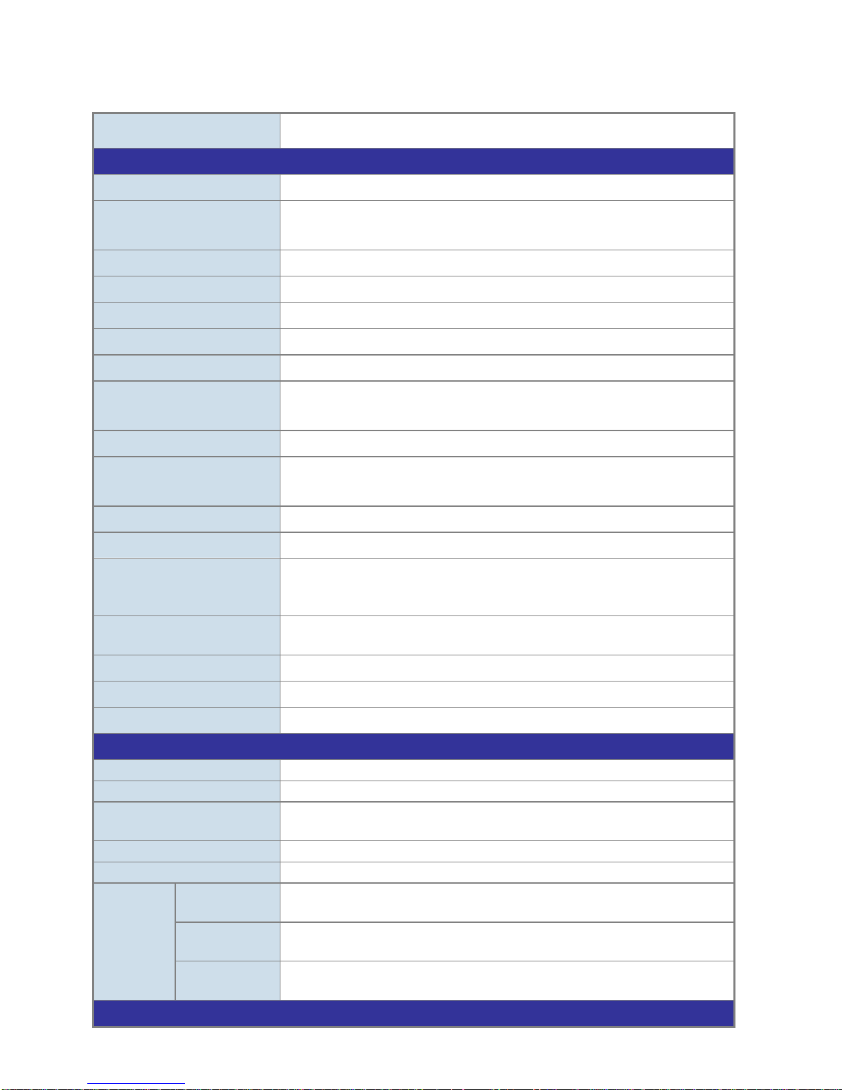
IFS NS3502-8P-2S User Manual
26
1.5 Product Specification
Product NS3502-8P-2S
Hardware Specification
Copper Ports 8 10/ 100/1000Base-T RJ-45 Auto-MDI/MDI-X ports
SFP/mini-GBIC Slots
2 1000Base-SX/LX/BX SFP interfaces (Port-9 and Port-10)
Compatible with 100Base-FX SFP
Console Port 1 x RS-232 DB9 serial port (115200, 8, N, 1)
Switch Architecture Store-and-Forward
Switch Fabric 20Gbps / non-blocking
Address Table 8K entries, automatic source address learning and ageing
Share data Buffer 1392 kilobytes
Flow Control
IEEE 802.3x Pause Frame for Full-Duplex
Back pressure for Half-Duplex
Jumbo Frame 9Kbytes
Reset Button
< 5 seconds: System reboot
> 10 seconds: Factory Default
Dimension (W x D x H) 330 x 155 x 43.5 mm, 1U high
Weight
1.8kg
LED
Power, FAN Alert,
Link/Act per Gigabit port,
PoE In-Use for port-1~ 8
Power Consumption
Max. 172.9 watts /
589.6 BTU
Power Requirement – AC
AC 100~240V, 50/60Hz
Operating Temperature
0 to 50®C (32 to 122®F)
Limited Warranty
3 Years
Power over Ethernet
PoE Standard
IEEE 802.3af / at PoE / PSE
PoE Power Supply Type
End-Span
PoE Power Output
Per Port 56V DC.
Max. 30.8 watts
Power Pin Assignment
1/2(+), 3/6(-)
PoE Power Budget
150 Watts
PoE Ability
Number of PD
@ 7Watts
8
Number of PD
@ 15.4Watts
8
Number of PD
@ 30.8Watts
4
Layer 2 Function
Page 27

IFS NS3502-8P-2S User Manual
27
Basic Management
Interfaces
Console, Telnet, Web Browser, SNMPv1, v2c
Secure Management
Interface
SSH, SSL, SNMP v3
Port configuration
Port disable/enable.
Auto-negotiation 10/100/1000Mbps full and half duplex mode
selection.
Flow Control disable / enable.
Bandwidth control on each port.
Power saving mode control
Port Status
Display each port’s speed duplex mode, link status, Flow control
status.
Auto negotiation status, trunk status.
Port Mirroring
TX / RX / Both
Many to 1 monitor
VLAN
802.1Q Tagged Based VLAN ,up to 256 VLAN groups
Q-in-Q tunneling
Private VLAN Edge (PVE)
MAC-based VLAN
Protocol-based VLAN
Voice VLAN
MVR (Multicast VLAN Registration)
Up to 256 VLAN groups, out of 4096 VLAN IDs
Link Aggregation
IEEE 802.3ad LACP / Static Trunk
Support 5 groups of 10-Port trunk support
QoS
Traffic classification based, Strict priority and WRR
8-level priority for switching
- Port Number
- 802.1p priority
- 802.1Q VLAN tag
- DSCP/TOS field in IP Packet
IGMP Snooping
IGMP (v1/v2/v3) Snooping, up to 255 multicast Groups
IGMP Querier mode support
MLD Snooping
MLD (v1/v2) Snooping, up to 255 multicast Groups
MLD Querier mode support
Access Control List
IP-Based ACL / MAC-Based ACL
Up to 123 entries
Bandwidth Control
Per port bandwidth control
Ingress: 500Kb~80Mbps
Egress: 64Kb~80Mbps
Page 28

IFS NS3502-8P-2S User Manual
28
SNMP MIBs
RFC-1213 MIB-II
IF-MIB
RFC-1493 Bridge MIB
RFC-1643 Ethernet MIB
RFC-2863 Interface MIB
RFC-2665 Ether-Like MIB
RFC-2737 Entity MIB
RFC-2618 RADIUS Client MIB
RFC-2933 IGMP-STD-MIB
RFC3411 SNMP-Frameworks-MIB
IEEE 802.1X PAE
LLDP
MAU-MIB
Standards Conformance
Regulation Compliance FCC Part 15 Class A, CE
Standards Compliance
IEEE 802.3 10Base-T
IEEE 802.3u 100Base-TX/100Base-FX
IEEE 802.3z Gigabit SX/LX
IEEE 802.3ab Gigabit 1000T
IEEE 802.3x Flow Control and Back pressure
IEEE 802.3ad Port trunk with LACP
IEEE 802.1d Spanning tree protocol
IEEE 802.1w Rapid spanning tree protocol
IEEE 802.1s Multiple spanning tree protocol
IEEE 802.1p Class of service
IEEE 802.1Q VLAN Tagging
IEEE 802.1x Port Authentication Network Control
IEEE 802.1ab LLDP
IEEE 802.3af Power over Ethernet
IEEE 802.3at Power over Ethernet PLUS
RFC 768 UDP
RFC 793 TFTP
RFC 791 IP
RFC 792 ICMP
RFC 2068 HTTP
RFC 1112 IGMP version 1
RFC 2236 IGMP version 2
RFC 3376 IGMP version 3
RFC 2710 MLD version 1
FRC 3810 MLD version 2
Page 29
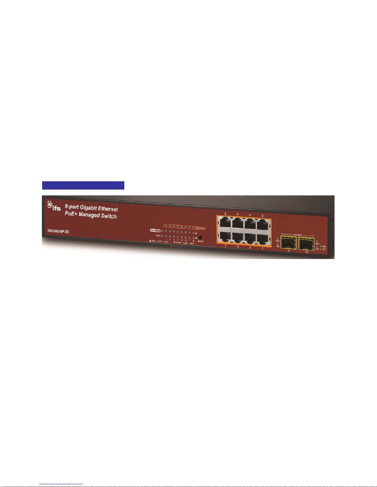
IFS NS3502-8P-2S User Manual
29
2. INSTALLATION
This section describes the hardware features and installation of the Managed Switch on the desktop
or rack mount. For easier management and control of the Managed Switch, familiarize yourself with
its display indicators, and ports. Front panel illustrations in this chapter display the unit LED
indicators. Before connecting any network device to the Managed Switch, please read this chapter
completely.
2.1 Hardware Description
2.1.1 Switch Front Panel
The unit front panel provides a simple interface monitoring the switch. Figure 2-1 shows the front
panel of the Managed Switch.
NS3502-8P-2S Front Panel
Figure 2-1: NS3502-8P-2S front panel.
■ Gigabit TP interface
10/100/1000Base-T Copper, RJ-45 Twist-Pair: Up to 100 meters.
■ SFP slots
100/1000Base-X mini-GBIC slot, SFP (Small Factor Pluggable) transceiver module: From 550
meters (Multi-mode fiber), up to 10/30/50/70/120 kilometers (Single-mode fiber).
■ Reset button
At the left of front panel, the reset button is designed for reboot the Managed Switch without
turn off and on the power. The following is the summary table of Reset button functions:
Page 30
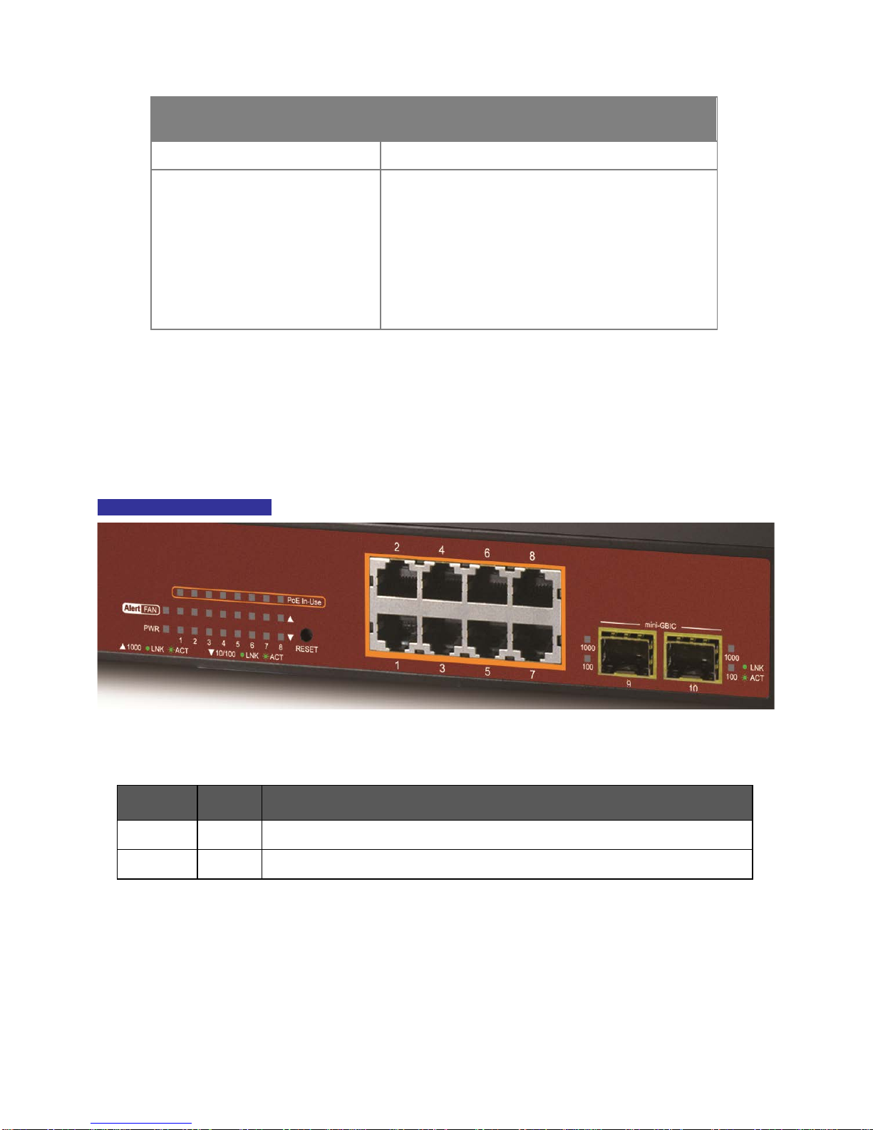
IFS NS3502-8P-2S User Manual
30
Reset Button Pressed and
Released
Function
< 5 sec: System reboot Reboot the Managed Switch
> 10 sec: Factory Default
Reset the Managed Switch to Factory Default
configuration. The Managed Switch will then
reboot and load the default settings as below:
。 Default Username: admin
。 Default Password: admin
。 Default IP address: 192.168.0.100
。 Subnet mask: 255.255.255.0
。
Default Gateway: 192.168.0.254
2.1.2 LED Indications
The front panel LEDs indicates instant status of port links, data activity and system power; helps
monitor and troubleshoot when needed. Figure 2-2 shows the LED indications of these Managed
Switches.
NS3502-8P-2S LED indication
Figure 2-2: NS3502-8P-2S LED panel
System
LED Color Function
FAN Alert Green
Lights to indicate that the fan is fail.
PWR Green
Lights to indicate that the Switch has power.
Page 31

IFS NS3502-8P-2S User Manual
31
Per 10/100/1000Mbps port
LED Color Function
PoE
In-Use
Orange
Lights to indicate the port is providing 52VDC in-line power
Off: indicate the connected device is not a PoE Powered Device (PD)
1000
LNK/ACT
Green
Lights to indicate the port is running in 1000Mbps speed and
successfully established.
Blink: indicate that the switch is actively sending or receiving data
over that port.
10/100
LNK/ACT
Green
Lights to indicate the port is running in 10/100Mbps speed and
successfully established.
Blink: indicate that the switch is actively sending or receiving data over
that port.
Per 100/1000Base-X SFP interfaces
LED Color Function
1000 Green
Lights to indicate the link through that port is successfully established.
Blink: indicate that the switch is actively sending or receiving data over
that port.
100 Green
Lights to indicate the link through that port is successfully established.
Blink: indicate that the switch is actively sending or receiving data over
that port.
2.1.3 Switch Rear Panel
The rear panel of the Managed Switch indicates an AC inlet power socket, which accepts input
power from 100 to 240V AC, 50-60Hz. Figure 2-3 shows the rear panel of these Managed Switches
NS3502-8P-2S Rear Panel
Figure 2-3: Rear panel of NS3502-8P-2S
■ AC Power Receptacle
For compatibility with electric service in most areas of the world, the Managed Switch’s power
supply automatically adjusts to line power in the range 100-240VAC and 50/60 Hz.
Plug the female end of the power cord firmly into the receptacle on the rear panel of the
Managed Switch. Plug the other end of the power cord into an electric service outlet then the
power will be ready.
Page 32

IFS NS3502-8P-2S User Manual
32
Power Notice:
The device is a power-required device, it means, it will not work till it is powered. If
your networks should active all the time, please consider using UPS (Uninterrupted
Power Supply) for your device. It will prevent you from network data loss or
network downtime.
In some area, installing a surge suppression device may also help to protect your
Managed Switch from being damaged by unregulated surge or current to the
Switch or the power adapter.
■ Console Port
The console port is a DB9, RS-232 male serial port connector. It is an interface for connecting a
terminal directly. Through the console port, it provides rich diagnostic information includes IP
Address setting, factory reset, port management, link status and system setting. Users can use
the attached RS-232 cable in the package and connect to the console port on the device. After
the connection, users can run any terminal emulation program (Hyper Terminal, ProComm
Plus, Telex, Winterm and so on) to enter the startup screen of the device.
Page 33

IFS NS3502-8P-2S User Manual
33
2.2 Install the Switch
This section describes how to install your Managed Switch and make connections to the Managed
Switch. Please read the following topics and perform the procedures in the order being presented.
To install your Managed Switch on a desktop or shelf, simply complete the following steps.
2.2.1 Desktop Installation
To install the Managed Switch on desktop or shelf, please follows these steps:
Step1: Attach the rubber feet to the recessed areas on the bottom of the Managed Switch.
Step2: Place the Managed Switch on the desktop or the shelf near an AC power source, as shown in
Figure 2-4.
Figure 2-4: Place the Managed Switch on the desktop
Step3: Keep enough ventilation space between the Managed Switch and the surrounding objects.
When choosing a location, please keep in mind the environmental restrictions
discussed in Chapter 1, Section 4, and Specification.
Step4: Connect the Managed Switch to network devices.
Connect one end of a standard network cable to the 10/100/1000 RJ-45 ports on the front of
the Managed Switch
Connect the other end of the cable to the network devices such as printer servers,
workstations or routers…etc.
Connection to the Managed Switch requires UTP Cate
gory 5 network cabling with
RJ-
45 tips. For more information, please see the Cabling Specification in Appendix
A.
Page 34

IFS NS3502-8P-2S User Manual
34
Step5: Supply power to the Managed Switch.
Connect one end of the power cable to the Managed Switch.
Connect the power plug of the power cable to a standard wall outlet.
When the Managed Switch receives power, the Power LED should remain solid Green.
2.2.2 Rack Mounting
To install the Managed Switch in a 19-inch standard rack, please follows the instructions described
below.
Step1: Place the Managed Switch on a hard flat surface, with the front panel positioned towards the
front side.
Step2: Attach the rack-mount bracket to each side of the Managed Switch with supplied screws
attached to the package.
Figure 2-5 shows how to attach brackets to one side of the Managed Switch.
Figure 2-5: Attach brackets to the Managed Switch.
You must use the screws supplied with the mounting brackets. Damage
caused to the parts by using incorrect screws would invalidate the warranty.
Step3: Secure the brackets tightly.
Step4: Follow the same steps to attach the second bracket to the opposite side.
Step5: After the brackets are attached to the Managed Switch, use suitable screws to securely
attach the brackets to the rack, as shown in Figure 2-6.
Page 35

IFS NS3502-8P-2S User Manual
35
Figure 2-6: Mounting NS3502-8P-2S in a Rack
Step6: Proceeds with the steps 4 and steps 5 of session 2.2.1 Desktop Installation to connect the
network cabling and supply power to the Managed Switch.
2.2.3 Installing the SFP transceiver
The sections describe how to insert an SFP transceiver into an SFP slot.
The SFP transceivers are hot-pluggable and hot-swappable. You can plug-in and out the transceiver
to/from any SFP port without having to power down the Managed Switch. As the Figure 2-7
appears.
Figure 2-7: Plug-in the SFP transceiver
Approved IFS SFP Transceivers
IFS Managed Switch supports both Single mode and Multi-mode SFP transceiver. The following list
of approved IFS SFP transceivers is correct at the time of publication:
Page 36

IFS NS3502-8P-2S User Manual
36
Gigabit SFP Transceiver modules
IFS Model
SFP Description
S30-1SLC/A-10 SFP, LC Connector, Single Mode, Gigabit, 1 fiber, 1310nm/1550nm, 10km , A
End
S30-1SLC/A-20 SFP, LC Connector, Single Mode, Gigabit, 1 fiber, 1310nm/1550nm, 20km, A
End
S30-1SLC/A-60 SFP, LC Connector, Single Mode, Gigabit, 1 fiber, 1310nm/1550nm, 60km, A
End
S30-1SLC/B-10 SFP, LC Connector, Single Mode, Gigabit, 1 fiber, 1550nm/1310nm, 10km , B
End
S30-1SLC/B-20 SFP, LC Connector, Single Mode, Gigabit, 1 fiber, 1550nm/1310nm, 20km, B
End
S30-1SLC/B-60 SFP, LC Connector, Single Mode, Gigabit, 1 fiber, 1550nm/1310nm, 60km, B
End
S30-2MLC SFP, LC Connector, Multi-Mode, Gigabit, 2 fiber,850nm/850nm, 550m
S30-2MLC-2 SFP, LC Connector, Multi-Mode, Gigabit, 2 fiber,1310nm/1310nm, 2km
S30-2SLC-10 SFP, LC Connector, Single Mode, Gigabit, 2 fiber,1310nm/1310nm, 10km
S30-2SLC-30 SFP, LC Connector, Single Mode, Gigabit, 2 fiber,1310nm/1310nm, 30km
S30-2SLC-70 SFP, LC Connector, Single Mode, Gigabit, 2 fiber,1550nm/1550nm, 70km
S30-RJ SFP, RJ-45, Gigabit, 100m
Fast Ethernet SFP Transceiver modules
S20-1SLC/A-20
SFP, LC Connector, Single Mode, 10/100 Fast Ethernet, 1 fiber, 1310nm/155
20km , A End
S20-1SLC/B-20
SFP, LC Connector, Single Mode, 10/100 Fast Ethernet, 1 fiber, 1310nm/1
55
20km , B End
S20-2MLC-2 SFP, LC Connector, Multi-Mode
, 10/100 Fast Ethernet, 2 fiber,1310nm/1310n
S20-2SLC-20
SFP, LC Connector, Single Mode, 10/100 Fast Ethernet, 2 fiber,1310nm/1310
20km
Page 37

IFS NS3502-8P-2S User Manual
37
It recommends using IFS SFPs on the Managed
Switch. If you insert a SFP
transceiver that is not supported, the Managed
Switch will not recognize
it.
Before connect the other Managed Switches, workstation or Media Converter.
1. Make sure both side of the SFP transceiver are with the same media type, for example:
1000Base-SX to 1000Base-SX, 1000Bas-LX to 1000Base-LX.
2. Check the fiber-optic cable type match the SFP transceiver model.
To connect to 1000Base-SX SFP transceiver, use the Multi-mode fiber cable- with one side
must be male duplex LC connector type.
To connect to 1000Base-LX SFP transceiver, use the Single-mode fiber cable-with one side
must be male duplex LC connector type.
Connect the fiber cable
1. Attach the duplex LC connector on the network cable into the SFP transceiver.
2. Connect the other end of the cable to a device – switches with SFP installed, fiber NIC on a
workstation or a Media Converter...
3. Check the LNK/ACT LED of the SFP slot on the front of the Managed Switch. Ensure that the SFP
transceiver is operating correctly.
4. Check the Link mode of the SFP port if the link failed. Co works with some fiber-NICs or Media
Converters, set the Link mode to “1000 Force” or “100 Force” is needed.
Remove the transceiver module
1. Make sure there is no network activity by consult or check with the network administrator. Or
through the management interface of the switch/converter (if available) to disable the port in
advance.
2. Remove the Fiber Optic Cable gently.
3. Turn the handle of the SFP module to horizontal.
4. Pull out the module gently through the handle.
Page 38

IFS NS3502-8P-2S User Manual
38
Figure 2-8: Pull out the SFP transceiver
Never pull out the module without pull the handle or the push bolts on
the module. Direct pull out the module with violent could damage the
module and SFP module slot of the Managed Switch.
Page 39

IFS NS3502-8P-2S User Manual
39
3. SWITCH MANAGEMENT
This chapter explains the methods that you can use to configure management access to the
Managed Switch. It describes the types of management applications and the communication and
management protocols that deliver data between your management device (workstation or
personal computer) and the system. It also contains information about port connection options.
This chapter covers the following topics:
Requirements
Management Access Overview
Administration Console Access
Web Management Access
SNMP Access
Standards, Protocols, and Related Reading
3.1 Requirements
Workstations of subscribers running Windows 2000/XP, 2003, Vista/7, 2008, MAC OS9 or
later, Linux, UNIX or other platform compatible with TCP/IP protocols.
Workstation installed with Ethernet NIC (Network Interface Card)
Serial Port connect (Terminal)
• Above PC with COM Port (DB9 / RS-232) or USB-to-RS-232 converter
Ethernet Port connect
• Network cables - Use standard network (UTP) cables with RJ45 connectors.
Above Workstation installed with WEB Browser and JAVA runtime environment Plug-in
It is recom
mended to use Internet Explorer 7.0 or above to access
Managed
Switch.
Page 40

IFS NS3502-8P-2S User Manual
40
3.2 Management Access Overview
The Managed Switch gives you the flexibility to access and manage it using any or all of the
following methods:
An administration console
Web browser interface
An external SNMP-based network management application
The administration console and Web browser interface support are embedded in the Managed
Switch software and are available for immediate use. Each of these management methods has their
own advantages. Table 3-1 compares the three management methods.
Method Advantages Disadvantages
Console
• No IP address or subnet needed
• Text-based
• Telnet functionality and
HyperTerminal built into
Windows
95/98/NT/2000/ME/XP
operating systems
• Secure
• Must be near switch or use dial-up
connection
• Not convenient for remote users
• Modem connection may prove to be
unreliable or slow
Web
Browser
• Ideal for configuring the switch
remotely
• Compatible with all popular
browsers
• Can be accessed from any
location
•
Most visually appealing
• Security can be compromised
(hackers need only know the IP
address and subnet mask)
• May encounter lag times on poor
connections
SNMP
Agent
• Communicates with switch
functions at the MIB level
• Based on open standards
• Requires SNMP manager software
• Least visually appealing of all three
methods
• Some settings require calculations
• Security can be compromised
(hackers need only know the
community name)
Table 3-1: Management Methods Comparison
Page 41

IFS NS3502-8P-2S User Manual
41
3.3 Administration Console
The administration console is an internal, character-oriented, and command line user interface for
performing system administration such as displaying statistics or changing option settings. Using this
method, you can view the administration console from a terminal, personal computer, Apple
Macintosh, or workstation connected to the switch's console (serial) port.
There are two ways to use this management method: via direct access or modem port access. The
following sections describe these methods. For more information about using the console, refer to
Chapter 5 Command Line Interface Console Management.
Figure 3-1: Console management
Direct Access
Direct access to the administration console is achieved by directly connecting a terminal or a PC
equipped with a terminal-emulation program (such as HyperTerminal) to the Managed Switch
console (serial) port.
When using this management method, a straight DB9 RS-232 cable is required to connect the
switch to the PC. After making this connection, configure the terminal-emulation program to use
the following parameters:
The default parameters are:
115200 bps
8 data bits
No parity
1 stop bit
Page 42

IFS NS3502-8P-2S User Manual
42
Figure 3-2: Terminal parameter settings
You can change these settings, if desired, after you log on. This management method is often
preferred because you can remain connected and monitor the system during system reboots. Also,
certain error messages are sent to the serial port, regardless of the interface through which the
associated action was initiated. A Macintosh or PC attachment can use any terminal-emulation
program for connecting to the terminal serial port. A workstation attachment under UNIX can use
an emulator such as TIP.
3.4 Web Management
The Managed Switch offers management features that allow users to manage the Managed Switch
from anywhere on the network through a standard browser such as Microsoft Internet Explorer.
After you set up your IP address for the switch, you can access the Managed Switch's Web interface
applications directly in your Web browser by entering the IP address of the Managed Switch.
Figure 3-3: Web management
Page 43

IFS NS3502-8P-2S User Manual
43
You can then use your Web browser to list and manage the Managed Switch configuration
parameters from one central location, just as if you were directly connected to the Managed
Switch's console port. Web Management requires either Microsoft Internet Explorer 7.0 or later,
Safari or Mozilla Firefox 1.5 or later.
Figure 3-4: Web main screen of Managed Switch
3.5 SNMP-Based Network Management
You can use an external SNMP-based application to configure and manage the Managed Switch,
such as SNMP Network Manager, HP Openview Network Node Management (NNM) or What’s Up
Gold. This management method requires the SNMP agent on the switch and the SNMP Network
Management Station to use the same community string. This management method, in fact, uses
two community strings: the get community string and the set community string. If the SNMP
Net-work management Station only knows the set community string, it can read and write to the
MIBs. However, if it only knows the get community string, it can only read MIBs. The default gets
and sets community strings for the Managed Switch are public.
Page 44

IFS NS3502-8P-2S User Manual
44
Figure 3-5: SNMP management
Page 45

IFS NS3502-8P-2S User Manual
45
4. WEB CONFIGURATION
This section introduces the configuration and functions of the Web-Based management.
About Web-based Management
The Managed Switch offers management features that allow users to manage the Managed Switch
from anywhere on the network through a standard browser such as Microsoft Internet Explorer.
The Web-Based Management supports Internet Explorer 7.0. It is based on Java Applets with an aim
to reduce network bandwidth consumption, enhance access speed and present an easy viewing
screen.
By default, IE7.0 or
later version does not allow Java Applets to open sockets.
The user has to explicitly modify the browser setting to enable Java Applets to
use network ports.
The Managed Switch can be configured through an Ethernet connection, make sure the manager PC
must be set on same the IP subnet address with the Managed Switch.
For example, the default IP address of the IFS Managed Switch is 192.168.0.100, then the manager
PC should be set at 192.168.0.x (where x is a number between 1 and 254, except 100), and the
default subnet mask is 255.255.255.0.
If you have changed the default IP address of the Managed Switch to 192.168.1.1 with subnet mask
255.255.255.0 via console, then the manager PC should be set at 192.168.1.x (where x is a number
between 2 and 254) to do the relative configuration on manager PC.
Figure 4-1-1: Web Management
Page 46

IFS NS3502-8P-2S User Manual
46
Logging on the switch
1. Use Internet Explorer 7.0 or above Web browser. Enter the factory-default IP address to access
the Web interface. The factory-default IP Address as following:
http://192.168.0.100
2. When the following login screen appears, please enter the default username "admin" with
password “admin” (or the username/password you have changed via console) to login the main
screen of Managed Switch. The login screen in Figure 4-1-2 appears.
Figure 4-1-2: Login screen
Default User name: admin
Default Password: admin
After entering the username and password, the main screen appears as Figure 4-1-3.
Page 47

IFS NS3502-8P-2S User Manual
47
Figure 4-1-3: Default main page
Now, you can use the Web management interface to continue the switch management or manage the
Managed Switch by Web interface. The Switch Menu on the left of the web page let you access all the
commands and statistics the Managed Switch provides.
1. It is recommended to use Internet Explorer 7.0 or above to access
Managed Switch.
2. The changed IP address take effect immediately after click on the Save
button, you need to use the new IP address to access the Web interface.
3. For security reason, please change and memorize the new password after
this first setup.
4. Only accept command in lowercase letter under web interface.
Page 48

IFS NS3502-8P-2S User Manual
48
4.1 Main Web Page
The IFS Managed Switch provides a Web-based browser interface for configuring and managing it. This
interface allows you to access the Managed Switch using the Web browser of your choice. This chapter
describes how to use the Managed Switch’s Web browser interface to configure and manage it.
Figure 4-1-4: Main Page
Panel Display
The web agent displays an image of the Managed Switch’s ports. The Mode can be set to display
different information for the ports, including Link up or Link down. Clicking on the image of a port
opens the Port Statistics page.
The port states are illustrated as follows:
State Disabled Down Link
RJ-45 Ports
SFP Ports
Main Menu
Using the onboard web agent, you can define system parameters, manage and control the Managed
Switch, and all its ports, or monitor network conditions. Via the Web-Management, the administrator
Main Functions
SFP Port Link Status Copper Port Link
Page 49

IFS NS3502-8P-2S User Manual
49
can setup the Managed Switch by select the functions those listed in the Main Function. The screen in
Figure 4-1-5 appears.
Figure 4-1-5: Managed Switch Main Functions Menu
Page 50

IFS NS3502-8P-2S User Manual
50
4.2 System
Use the System menu items to display and configure basic administrative details of the Managed
Switch. Under System the following topics are provided to configure and view the system information:
This section has the following items:
■ System Information The switch system information is provided here.
■ IP Configuration Configure the switch-managed IP information on this page.
■ IPv6 Configuration Configure the switch-managed IPv6 information on this page.
■ Users Configuration
This page provides an ove
rview of the current users. Currently
the only way to login as another user on the web server is to
close and reopen the browser.
■ Privilege Levels
This page provides an overview of the privilege levels.
■ NTP Configuration Configure NTP on this page.
■ UPnP Configure UPnP on this page.
■ DHCP Relay Configure DHCP Relay on this page.
■ DHCP Relay Statistics This page provides statistics for DHCP relay.
■ CPU Load This page displays the CPU load, using a SVG graph.
■ System Log The switch system log information is provided here.
■ Detailed Log The switch system detailed log information is provided here.
■ Remote Syslog Configure remote syslog on this page.
■ LED Power Reduction Configuration LED power reduction on this page.
■ EEE Power Reduction
Configuration energy efficient ethernet power reduction on
this page
■ Thermal Protection Configure thermal protection on this page.
■ Web Firmware
Upgrade
This page facilitates an update of the firmware cont
rolling the
switch.
■ TFTP Firmware
Upgrade
Upgrade the firmware via TFTP server
■ Configuration Backup
You can save the switch configuration. The configuration file
is in XML format with a hierarchy of tags.
■
Configuration Upload
You can load the switch configuration. The configuration file
is in XML format with a hierarchy of tags.
■ Image Select
Configuration active or alternate firmware on this page.
■ Factory Default
You can reset the configuration of the stack switch on this
page. Only the IP configuration is retained.
■ System Reboot
You can restart the stack switch on this page. After restart,
the stack switch will boot normally.
Page 51

IFS NS3502-8P-2S User Manual
51
4.2.1 System Information
The System Info page provides information for the current device information. System Info page helps
a switch administrator to identify the hardware MAC address, software version and system uptime. The
screen in Figure 4-2-1 appears.
Figure 4-2-1: System Information page screenshot
The page includes
the following
fields: Object
Description
• Contact
The system contact configured in Configuration | System | Information
| System Contact.
• Name
The system name configured in Configuration | System | Information |
System Name.
• Location
The system location configured in Configuration | System | Information
| System Location.
• MAC Address
The MAC Address of this switch.
• System Date
The current (GMT) system time and date. The system time is obtained
through the configured SNTP Server, if any.
• System Uptime
The period of time the device has been operational.
• Software
Version
The software version of the switch.
• Software Date
The date when the switch software was produced.
Page 52

IFS NS3502-8P-2S User Manual
52
Buttons
Auto-refresh : Check this box to enable an automatic refresh of the page at regular intervals.
: Click to refresh the page; any changes made locally will be undone.
4.2.2 IP Configuration
The IP Configuration includes the IP Address, Subnet Mask and Gateway. The Configured column is
used to view or change the IP configuration. Fill up the IP Address, Subnet Mask and Gateway for the
device. The screen in Figure 4-2-2 appears.
Figure 4-2-2: IP Configuration page screenshot
The Current column is used to show the active IP configuration.
Object Description
• DHCP Client
Enable the DHCP client by checking this box. If DHCP fails and the
configured IP address is zero, DHCP will retry. If DHCP fails and the
configured IP address is non-zero, DHCP will stop and the configured IP
settings will be used. The DHCP client will announce the configured
System Name as hostname to provide DNS lookup.
• IP Address
Provide the IP address of this switch in dotted decimal notation.
• IP Mask
Provide the IP mask of this switch dotted decimal notation.
• IP Router
Provide the IP address of the router in dotted decimal notation.
• VLAN ID
Provide the managed VLAN ID. The allowed range is 1 through
4095
.
Page 53

IFS NS3502-8P-2S User Manual
53
• DNS Server
Provide the IP address of the DNS Server in dotted decimal notation.
• DNS Proxy
When DNS proxy is enabled, DUT will relay DNS requests to the current
configured DNS server on DUT, and reply as a DNS resolver to the client
device on the network.
Buttons
: Click to save changes.
: Click to undo any changes made locally and revert to previously saved values.
: Click to undo any changes made locally and revert to previously saved values.
4.2.3 IPv6 Configuration
Configure the switch-managed IPv6 information on this page.
The Configured column is used to view or change the IPv6 configuration. The Current column is used to
show the active IPv6 configuration. The screen in Figure 4-2-3 appears.
Figure 4-2-3: IPv6 Configuration page screenshot
The page includes the following fields:
Object Description
• Auto
• Configuration
Enable IPv6 auto-configuration by checking this box. If it fails, the
configured IPv6 address will be zero.
The router may delay responding to a router solicitation for a few seconds,
the total time needed to complete auto-configuration can be significantly
longer.
Page 54

IFS NS3502-8P-2S User Manual
54
• Address
Provide the IPv6 address of this switch. IPv6 address is in 128-bit records
represented as eight fields of up to four hexadecimal digits with a colon
separate each field (:). For example, ‘fae0::013:4fefe:dea4:34d4’
. The symbol '::' is a special syntax that can be used as a shorthand way of
representing multiple 16-bit groups of contiguous zeros; but it can only
appear once. It also used a following legally IPv4 address. For example, '::
192.1.2.34’.
• Prefix
Provide the IPv6 Prefix of this switch. The allowed range is 1 through 128.
• Router
Provide the IPv6 gateway address of this switch. IPv6 address is in 128-bit
records represented as eight fields of up to four hexadecimal digits with a
colon separate each field (:). For example, ‘fae0::013:4fefe:dea4:34d4’. The
symbol '::' is a special syntax that can be used as a shorthand way of
representing multiple 16-bit groups of contiguous zeros; but it can only
appear once. It also used a following legally IPv4 address. For example,
'::192.1.2.34'.
Provide the IPv6 SNTP Server address of this switch. IPv6 address is in
128-bit records represented as eight fields of up to four hexadecimal digits
with a colon separate each field (:). For example,
'fae0::013:4fefe:dea4:34d4’. The symbol '::' is a special syntax that can be
used as a shorthand way of representing multiple 16-bit groups of
contiguous zeros; but it can only appear once. It also used a following
legally IPv4 address. For example, '::192.1.2.34'.
• VLAN ID
Provide the managed VLAN ID. The allowed range is 1 through 4095
Buttons
: Click to save changes.
: Click to undo any changes made locally and revert to previously saved values.
4.2.4 Users Configuration
This page provides an overview of the current users. Currently the only way to login as another user on
the web server is to close and reopen the browser. After setup completed, please press “Save” button
to take effect. Please login web interface with new user name and password, the screen in Figure 4-2-4
appears.
Page 55

IFS NS3502-8P-2S User Manual
55
Figure 4-2-4: Users Configuration page screenshot
The page includes the following fields:
Object Description
• Username
The name identifying the user. This is also a link to Add/Edit User.
• Privilege Level
The privilege level for the user.
Buttons
: Click to add a new user.
Add / Edit User
This page configures a user – add, edit or delete user.
Figure 4-2-5: Add / Edit User Configuration page screenshot
The page includes the following fields:
Object Description
• Username
The name identifying the user.
• Password
The password of the user.
• Privilege Level
The privilege level for the user.
Buttons
: Click to save changes.
Page 56

IFS NS3502-8P-2S User Manual
56
: Click to undo any changes made locally and revert to previously saved values.
: Click to undo any changes made locally and return to the Users.
: Delete the current user. This button is not available for new configurations (Add new user)
Once the new user is added, the new user entry is shown in the Users Configuration page.
Figure 4-2-6: User Configuration page screenshot
After change the default password, if you forget the password. Please press
the “Reset” button in the front panel of the Managed Switch over 10 secon
ds
and then release
, the current setting includes VLAN, will be lost and the
Managed Switch will restore to the default mode.
Page 57

IFS NS3502-8P-2S User Manual
57
4.2.5 Privilege Levels
This page provides an overview of the privilege levels. After setup completed, please press “Save”
button to take effect. Please login web interface with new user name and password, the screen in
Figure 4-2-7 appears.
Figure 4-2-7: Privilege Levels Configuration page screenshot
Page 58

IFS NS3502-8P-2S User Manual
58
The page includes the following fields:
Object Description
• Group Name
The name identifying the privilege group. In most cases, a
privilege level group consists of a single module (e.g. LACP, RSTP
or QoS), but a few of them contains more than one. The following
description defines these privilege level groups in details:
System: Contact, Name, Location, Timezone, Log.
Security: Authentication, System Access Management, Port
(contains Dot1x port, MAC based and the MAC Address Limit),
ACL, HTTPS, SSH, ARP Inspection and IP source guard.
IP: Everything except 'ping'.
Port: Everything except 'VeriPHY'.
Diagnostics: 'ping' and 'VeriPHY'.
Maintenance: CLI- System Reboot, System Restore Default,
System Password, Configuration Save, Configuration Load and
Firmware Load. Web- Users, Privilege Levels and everything in
Maintenance.
Debug: Only present in CLI.
• Privilege Level
Every privilege level group has an authorization level for the
following sub groups: configuration read-only,
configuration/execute read-write, status/statistics read-only, and
status/statistics read-write (e.g. for clearing of statistics).
Buttons
: Click to save changes.
: Click to undo any changes made locally and revert to previously saved values.
Page 59

IFS NS3502-8P-2S User Manual
59
4.2.6 NTP Configuration
Configure NTP on this page.
NTP is an acronym for Network Time Protocol, a network protocol for synchronizing the clocks of
computer systems. NTP uses UDP (data grams) as transport layer. You can specify NTP Servers and set
GMT Time zone. The NTP Configuration screen in Figure 4-2-8 appears.
Figure 4-2-8: NTP Configuration page screenshot
The page includes the following fields:
Object Description
• Mode
Indicates the NTP mode operation. Possible modes are:
Enabled: Enable NTP mode operation. When enable NTP mode
operation, the agent forward and to transfer NTP messages
between the clients and the server when they are not on the
same subnet domain.
Disabled: Disable NTP mode operation.
• Timezone
Allow select the time zone according to current location of
switch.
• Server #
Provide the NTP IPv4 or IPv6 address of this switch. IPv6 address
is in 128-bit records represented as eight fields of up to four
hexadecimal digits with a colon separate each field (:). For
example, ‘fae0::013:4fefe:dea4:34d4’. The symbol '::' is a special
syntax that can be used as a shorthand way of representing
multiple 16-bit groups of contiguous zeros; but it can only appear
once. It also used a following legally IPv4 address. For example,
'::192.1.2.34'.
Page 60

IFS NS3502-8P-2S User Manual
60
Buttons
: Click to save changes.
: Click to undo any changes made locally and revert to previously saved values.
4.2.7 UPnP
Configure UPnP on this page.
UPnP is an acronym for Universal Plug and Play. The goals of UPnP are to allow devices to connect
seamlessly and to simplify the implementation of networks in the home (data sharing,
communications, and entertainment) and in corporate environments for simplified installation of
computer components. The UPnP Configuration screen in Figure 4-2-9 appears.
Figure 4-2-9: UPnP Configuration page screenshot
Page 61

IFS NS3502-8P-2S User Manual
61
The page includes the following fields:
Object Description
• Mode
Indicates the UPnP operation mode. Possible modes are:
Enabled: Enable UPnP mode operation.
Disabled: Disable UPnP mode operation.
When the mode is enabled, two ACEs are added automatically to
trap UPNP related packets to CPU. The ACEs are automatically
removed when the mode is disabled.
• TTL
The TTL value is used by UPnP to send SSDP advertisement
messages. Valid values are in the range 1 to 255.
• Advertising
Duration
The duration, carried in SSDP packets, is used to inform a control
point or control points how often it or they should receive a SSDP
advertisement message from this switch. If a control point does
not receive any message within the duration, it will think that the
switch no longer exists. Due to the unreliable nature of UDP, in
the standard it is recommended that such refreshing of
advertisements to be done at less than one-half of the
advertising duration. In the implementation, the switch sends
SSDP messages periodically at the interval one-half of the
advertising duration minus 30 seconds. Valid values are in the
range 100 to 86400.
Page 62

IFS NS3502-8P-2S User Manual
62
Buttons
: Click to save changes.
: Click to undo any changes made locally and revert to previously saved values.
Figure 4-2-10: UPnP devices shows on Windows My Network Places
4.2.8 DHCP Relay
Configure DHCP Relay on this page. DHCP Relay is used to forward and to transfer DHCP messages
between the clients and the server when they are not on the same subnet domain.
The DHCP option 82 enables a DHCP relay agent to insert specific information into a DHCP request
packets when forwarding client DHCP packets to a DHCP server and remove the specific information
from a DHCP reply packets when forwarding server DHCP packets to a DHCP client. The DHCP server
can use this information to implement IP address or other assignment policies. Specifically the option
works by setting two sub-options:
Circuit ID (option 1)
Remote ID (option2).
Page 63

IFS NS3502-8P-2S User Manual
63
The Circuit ID sub-option is supposed to include information specific to which circuit the request came
in on.
The Remote ID sub-option was designed to carry information relating to the remote host end of the
circuit.
The definition of Circuit ID in the switch is 4 bytes in length and the format is "vlan_id" "module_id"
"port_no". The parameter of "vlan_id" is the first two bytes represent the VLAN ID. The parameter of
"module_id" is the third byte for the module ID (in standalone switch it always equal 0, in stackable
switch it means switch ID). The parameter of "port_no" is the fourth byte and it means the port
number.
The Remote ID is 6 bytes in length, and the value is equal the DHCP relay agent’s MAC address. The
DHCP Relay Configuration screen in Figure 4-2-11 appears.
Figure 4-2-11: DHCP Relay Configuration page screenshot
The page includes the following fields:
Object Description
• Relay Mode
Indicates the DHCP relay mode operation. Possible modes are:
Enabled: Enable DHCP relay mode operation. When enable DHCP
relay mode operation, the agent forward and to transfer DHCP
messages between the clients and the server when they are not
on the same subnet domain. And the DHCP broadcast message
won't flood for security considered.
Disabled: Disable DHCP relay mode operation.
• Relay Server
Indicates the DHCP relay server IP address. A DHCP relay agent is
used to forward and to transfer DHCP messages between the
clients and the server when they are not on the same subnet
domain.
• Relay Information
Mode
Indicates the DHCP relay information mode option operation.
Possible modes are:
Enabled: Enable DHCP relay information mode operation. When
enable DHCP relay information mode operation, the agent insert
Page 64

IFS NS3502-8P-2S User Manual
64
specific information (option82) into a DHCP message when
forwarding to DHCP server and remove it from a DHCP message
when transferring to DHCP client. It only works under DHCP relay
operation mode enabled.
Disabled: Disable DHCP relay information mode operation.
• Relay Information
Policy
Indicates the DHCP relay information option policy. When enable
DHCP relay information mode operation, if agent receives a DHCP
message that already contains relay agent information. It will
enforce the policy. And it only works under DHCP relay
information operation mode enabled. Possible policies are:
Replace: Replace the original relay information when receive a
DHCP message that already contains it.
Keep: Keep the original relay information when receive a DHCP
message that already contains it.
Drop: Drop the package when receive a DHCP message that
already contains relay information.
Buttons
: Click to save changes.
: Click to undo any changes made locally and revert to previously saved values.
4.2.9 DHCP Relay Statistics
This page provides statistics for DHCP relay. The DHCP Relay Statistics screen in Figure 4-2-12 appears.
Figure 4-2-12: DHCP Relay Statistics page screenshot
The page includes the following fields:
Server Statistics
Object Description
Page 65

IFS NS3502-8P-2S User Manual
65
• Transmit to Server
The packets number that relayed from client to server.
• Transmit Error
The packets number has errors sending packets to clients.
• Receive form
Server
The packets number that received packets from server.
• Receive Missing
Agent Option
The packets number that received packets without agent
information options.
• Receive Missing
Circuit ID
The packets number that received packets which the Circuit ID
option was missing.
• Receive Missing
Remote ID
The packets number that received packets which Remote ID
option was missing.
• Receive Bad Circuit
ID
The packets number that the Circuit ID option did not match
known circuit ID.
• Receive Bad
Remote ID
The packets number that the Remote ID option did not match
known Remote ID.
Client Statistics
Object Description
• Transmit to Client
The packets number that relayed packets from server to client.
• Transmit Error
The packets number that error sending packets to servers.
• Receive form Client
The packets number that received packets from server.
• Receive Agent
Option
The packets number that received packets with relay agent
information option.
• Replace Agent
Option
The packets number that replaced received packets with relay
agent information option.
• Keep Agent Option
The packets number that keep received packets with relay agent
information option.
• Drop Agent Option
The packets number that dropped received packets with relay
agent information option.
Buttons
Auto-refresh : Check this box to enable an automatic refresh of the page at regular intervals.
: Click to refresh the page; any changes made locally will be undone.
: Clear all statistics.
Page 66

IFS NS3502-8P-2S User Manual
66
4.2.10 CPU Load
This page displays the CPU load, using a SVG graph.
The load is measured as averaged over the last 100ms, 1sec and 10 seconds intervals. The last 120
samples are graphed, and the last numbers are displayed as text as well.
In order to display the SVG graph, your browser must support the SVG format. Consult the SVG Wiki for
more information on browser support. Specifically, at the time of writing, Microsoft Internet Explorer
will need to have a plugin installed to support SVG. The CPU Load screen in Figure 4-2-13 appears.
Figure 4-2-13: CPU Load page screenshot
Buttons
Auto-refresh : Check this box to enable an automatic refresh of the page at regular intervals.
If your browser cannot display anything
in this page, please download Adobe
SVG tool and install it in your computer.
Page 67

IFS NS3502-8P-2S User Manual
67
4.2.11 System Log
The switch system log information is provided here. The System Log screen in Figure 4-2-14 appears.
Figure 4-2-14: System Log page screenshot
The page includes the following fields:
Object Description
• ID
The ID (>= 1) of the system log entry.
• Level
The level of the system log entry. The following level types are
supported:
Info: Information level of the system log.
Warning: Warning level of the system log.
Error: Error level of the system log.
All: All levels.
• Time
The time of the system log entry.
• Message
The message of the system log entry.
Buttons
Auto-refresh : Check this box to enable an automatic refresh of the page at regular intervals.
: Click to refresh the page; any changes made locally will be undone.
: Clear all statistics.
: Updates the system log entries, starting from the first available entry ID.
Page 68

IFS NS3502-8P-2S User Manual
68
: Updates the system log entries, ending at the last entry currently displayed.
: Updates the system log entries, starting from the last entry currently displayed.
: Updates the system log entries, ending at the last available entry ID.
4.2.12 Detailed Log
The switch system detailed log information is provided here. The Detailed Log screen in Figure 4-2-15
appears.
Figure 4-2-15: Detailed Log page screenshot
The page includes the following fields:
Object Description
• ID
The ID (>= 1) of the system log entry.
• Message
The message of the system log entry.
Buttons
: Click to refresh the page; any changes made locally will be undone.
: Updates the system log entries, starting from the first available entry ID.
: Updates the system log entries, ending at the last entry currently displayed.
: Updates the system log entries, starting from the last entry currently displayed.
: Updates the system log entries, ending at the last available entry ID.
Page 69

IFS NS3502-8P-2S User Manual
69
4.2.13 Remote Syslog
Configure remote syslog on this page. The Remote Syslog screen in Figure 4-2-16 appears.
Figure 4-2-16: Remote Syslog page screenshot
The page includes the following fields:
Object Description
• Mode
Indicates the server mode operation. When the mode operation
is enabled, the syslog message will send out to syslog server. The
syslog protocol is based on UDP communication and received on
UDP port 514 and the syslog server will not send
acknowledgments back sender since UDP is a connectionless
protocol and it does not provide acknowledgments. The syslog
packet will always send out even if the syslog server does not
exist. Possible modes are:
Enabled: Enable remote syslog mode operation.
Disabled: Disable remote syslog mode operation.
• Syslog Server IP
Indicates the IPv4 host address of syslog server. If the switch
provide DNS feature, it also can be a host name.
• Syslog Level
Indicates what kind of message will send to syslog server.
Possible modes are:
Info: Send information, warnings and errors.
Warning: Send warnings and errors.
Error: Send errors.
Buttons
: Click to save changes.
: Click to undo any changes made locally and revert to previously saved values.
Page 70

IFS NS3502-8P-2S User Manual
70
4.2.14 SMTP Configuration
Configure SMTP Configuration on this page. The SMTP Configuration screen in Figure 4-2-17 appears.
Figure 4-2-17: SMTP Configuration Page Screenshot
The page includes the following fields:
Object
Description
• SMTP Mode
Enabled
It is for you to enable SMTP mode function. This mode offers you
to configure SMTP server and SMTP account information, system
will refer it to send an E-mail for alarm noticing
• SMTP Server
It is for you to set up a specify SMTP server DNS name or IP
address. If it is inputted a DNS name, please remember to input
DNS server IP address at IP configuration page.
• SMTP Port
It is for you to input the SMTP server port number. As default is
"25".
• SMTP
Authentication
Enabled
As usual SMTP server is denied to relay a mail from a different
domain, so you have to enable this option and input your mail
account and password for SMTP sever authorizing to forward a
mail from different domain. For example, you want a SMTP
server which located on mail.123.com send a mail to
mail.456.net.com.
If you want to send the mail to a SMTP server which located on
the same domain or the same SMTP server, you don't have to
enable SMTP authentication.
• Authentication
User Name
It is for you to input your mail account name.
• Authentication
Password
It is for you to input your mail account password.
Page 71

IFS NS3502-8P-2S User Manual
71
• E-mail From
It is for you to input who send this mail.
• E-mail Subject
It is for you to input mail subject.
• E-mail 1 To
It is for you to input recipient mail address.
• E-mail 2 To
It is for you to input secondary recipient mail address.
Buttons
: Click to test SMTP server address.
: Click to save changes.
: Click to undo any changes made locally and revert to previously saved values.
4.2.15 LED Power Reduction
The LEDs power consumption can be reduced by lowering the LEDs intensity. LEDs intensity could for
example be lowered during night time, or they could be turn completely off. It is possible to configure
24 different hours of the day, at where the LEDs intensity should be set. The LED Power Reduction
screen in Figure 4-2-18 appears.
Figure 4-2-18: LED Power Reduction page screenshot
Page 72

IFS NS3502-8P-2S User Manual
72
The page includes the following fields:
Object Description
• Time
The time at which the LEDs intensity shall be set.
• Intensity
The LEDs intensity (100% = Full power, 0% = LED off).
• Maintenance Time
When a network administrator does maintenance of the switch
(e.g. adding or moving users) he might want to have full LED
intensity during the maintenance period. Therefore it is possible
to specify that the LEDs shall use full intensity a specific period of
time. Maintenance Time is the number of seconds that the LEDs
will have full intensity after either a port has changed link state,
or the LED pushbutton has been pushed.
Buttons
: Click to add time.
: Click to save changes.
: Click to undo any changes made locally and revert to previously saved values.
4.2.16 EEE Power Reduction
This page allows the user to inspect and configure the current EEE port settings.
EEE is a power saving option that reduces the power usage when there is very low traffic utilization (or
no traffic).
EEE works by powering down circuits when there is no traffic. When a port gets data to be transmitted
all circuits are powered up. The time it takes to power up the circuits is named wakeup time. The
default wakeup time is 17 us for 1Gbit links and 30 us for other link speeds. EEE devices must agree
upon the value of the wakeup time in order to make sure that both the receiving and transmitting
device has all circuits powered up when traffic is transmitted. The devices can exchange information
about the devices wakeup time using the LLDP protocol.
For maximizing the power saving, the circuit isn't started at once transmit data are ready for a port, but
is instead queued until 3000 bytes of data are ready to be transmitted. For not introducing a large
delay in case that data less than 3000 bytes shall be transmitted, data are always transmitted after 48
us, giving a maximum latency of 48 us + the wakeup time.
If desired it is possible to minimize the latency for specific frames, by mapping the frames to a specific
queue (done with QOS), and then mark the queue as an urgent queue. When an urgent queue gets
data to be transmitted, the circuits will be powered up at once and the latency will be reduced to the
wakeup time.
Page 73

IFS NS3502-8P-2S User Manual
73
The EEE Power Reduction screen in Figure 4-2-19 appears.
Figure 4-2-19: EEE Configuration page screenshot
The page includes the following fields:
Object Description
• Port
The switch port number of the logical EEE port.
• EEE Enable
Controls whether EEE is enabled for this switch port.
• EEE Urgent Queues
Queues set will activate transmission of frames as soon as any
data is available. Otherwise the queue will postpone the
transmission until 3000 bytes are ready to be transmitted.
Buttons
: Click to save changes.
: Click to undo any changes made locally and revert to previously saved values.
4.2.17 Thermal Protection
This page allows the user to inspect and configure the current setting for controlling thermal
protection. Thermal protection is used to protect the chip from getting overheated.
When the temperature exceeds the configured thermal protection temperature, ports will be turned
off in order to decrease the power consumption. It is possible to arrange the ports with different
priorities. Each priority can be given a temperature at which the corresponding ports shall be turned
off. The Thermal Protection screen in Figure 4-2-20 appears.
Page 74

IFS NS3502-8P-2S User Manual
74
Figure 4-2-20: Thermal Protection Configuration page screenshot
The page includes the following fields:
Object Description
• Temperature
settings for priority
groups
The temperature at which the ports with the corresponding
priority will be turned off. Temperatures between 0 and 255 C
are supported.
• Port priorities
The priority the port belongs to. 4 priorities are supported.
Buttons
: Click to save changes.
: Click to undo any changes made locally and revert to previously saved values.
Page 75

IFS NS3502-8P-2S User Manual
75
4.2.18 Web Firmware Upgrade
This page facilitates an update of the firmware controlling the switch. The Web Firmware Upgrade
screen in Figure 4-2-21 appears.
Figure 4-2-21: Web Firmware Upgrade page screenshot
To open Firmware Upgrade screen perform the folling:
1. Click System -> Web Firmware Upgrade.
2. The Firmware Upgrade screen is displayed as in Figure 4-2-21.
3. Click the “ “button of the main page, the system would pop up the file selection menu to
choose firmware.
4. Select on the firmware then click “ ”, the Software Upload Progress would show the file
upload status.
5. Once the software is loaded to the system successfully. The following screen appears. The system
will load the new software after reboot.
Figure 4-2-22: Software successfully loaded notice screen
DO NOT Power OFF the Managed Switch until the update progress is
complete.
Do not quit the Firmware Upgrade page without press the “OK” button -
after the image is loaded. Or the system won’t apply the new firmware.
User has to repeat the firmware upgrade processes again.
Page 76

IFS NS3502-8P-2S User Manual
76
4.2.19 TFTP Firmware Upgrade
The Firmware Upgrade page provides the functions to allow a user to update the Managed Switch
firmware from the TFTP server in the network. Before updating, make sure you have your TFTP server
ready and the firmware image is on the TFTP server. The TFTP Firmware Upgrade screen in Figure
4-2-23 appears.
Figure 4-2-23: TFTP Firmware Update page screenshot
The page includes the following fields:
Object Description
• TFTP Server IP
Fill in your TFTP server IP address.
• Firmware File
Name
The name of firmware image.
(Maximum length : 24 characters)
Buttons
: Click to upgrade firmware.
DO NOT Power OFF the Managed Switch until the update progress is
complete.
Do not quit the Firmware Upgrade page without press the “OK” button -
after the image is loaded. Or the system won’t apply the new firmware.
User has to repeat the firmware upgrade processes again.
4.2.20 Configuration Backup
This function allows backup and reload the current configuration of the Managed Switch to the local
management station. The Configuration Backup screen in Figure 4-2-24 appears.
Page 77

IFS NS3502-8P-2S User Manual
77
Figure 4-2-24: Configuration Save page screenshot
You can save/view or load the switch configuration. The configuration file is in XML format with a
hierarchy of tags:
Header tags:
<?xml version="1.0"?> and <configuration>. These tags are mandatory and must be present
at the beginning of the file.
Section tags: <pla
tform>, <global> an d <switch>. T he platfo rm se ction must be t he fir st se ction tag and t his
section must include the correct platform ID and version. The global section is optional and
includes configuration which is not related to specific switch ports. The switch section is
optional and includes configuration w hich is relate d to specif i c switch port s.
Module tags: <ip>, <mac>, <port> etc. These tags identify a module controlling specific parts of the
configuration.
Group tags: <port_table>, <vlan_table> etc. These tags identify a group of parameters, typically a table.
Parameter tags: <mode>, <entry> etc. These tags identify parameters for the specific section, module and
group. The <entry> tag is used for table entries.
Configuration parameters are represented as attribute values. When saving the configuration from the
switch, the entire configuration including syntax descriptions is included in the file. The file may then
be modified using an editor and loaded to a switch.
The examples below shows a small configuration file only including configuration of the MAC address
age time and the learning mode per port. When loading this file, only the included parameters will be
changed. This means that the age time will be set to 200 and the learn mode will be set to automatic.
Save Configuration
1. Press the “Save Configuration” button to save the current configuration in manager workstation.
The following screens in Figure 4-2-25 & 4-2-26 appear
Page 78

IFS NS3502-8P-2S User Manual
78
Figure 4-2-25: File Download screen
2. Chose the file save path in management workstation.
Figure 4-2-26: File save screen
Page 79

IFS NS3502-8P-2S User Manual
79
4.2.21 Configuration Upload
This function allows backup and reload the current configuration of the Managed Switch to the local
management station. The Configuration Upload screen in Figure 4-2-27 appears.
Figure 4-2-27: Configuration Upload page screenshot
Configuration Upload
1. Click the “ ” button of the main page, the system would pop up the file selection menu to
choose saved configuration.
Figure 4-2-28: Windows file selection menu popup
2. Select on the configuration file then click “ ”, the bottom of the browser shows the upload
status.
3. After down, the main screen appears “Transfer Completed”.
Page 80

IFS NS3502-8P-2S User Manual
80
4.2.22 Factory Default
You can reset the configuration of the stack switch on this page. Only the IP configuration is retained.
The new configuration is available immediately, which means that no restart is necessary. The Factory
Default screen in Figure 4-2-29 appears.
Figure 4-2-29: Factory Default page screenshot
Buttons
: Click to reset the configuration to Factory Defaults.
: Click to return to the Port State page without resetting the configuration.
After the “Factory” button be pressed and rebooted, the system will load the default IP settings as
following:
。 Default IP address: 192.168.0.100
。 Subnet mask: 255.255.255.0
。 Default Gateway: 192.168.0.254
。 The other setting value is back to disable or none.
To reset the Managed Switch to the Factory default setting, you can
also press the
hardware reset button at the front panel about 10 seconds. After the device be
rebooted. You can login the management WEB interface within the same subnet of
192.168.0.xx.
Hardware Reset
Page 81

IFS NS3502-8P-2S User Manual
81
4.2.23 System Reboot
The Reboot page enables the device to be rebooted from a remote location. Once the Reboot button is
pressed, user have to re-login the WEB interface about 60 seconds later, the System Reboot screen in
Figure 4-2-30 appears.
Figure 4-2-30: System Reboot page screenshot
Buttons
: Click to reboot the system.
: Click to return to the Port State page without reboot the system.
Page 82

IFS NS3502-8P-2S User Manual
82
4.3 Simple Network Management Protocol
4.3.1 SNMP Overview
The Simple Network Management Protocol (SNMP) is an application layer protocol that facilitates the
exchange of management information between network devices. It is part of the Transmission Control
Protocol/Internet Protocol (TCP/IP) protocol suite. SNMP enables network administrators to manage
network performance, find and solve network problems, and plan for network growth.
An SNMP-managed network consists of three key components: Network management stations (NMSs),
SNMP agents, Management information base (MIB) and network-management protocol:
。 Network management stations (NMSs):Sometimes called consoles, these devices execute
management applications that monitor and control network elements. Physically, NMSs are
usually engineering workstation-caliber computers with fast CPUs, megapixel color displays,
substantial memory, and abundant disk space. At least one NMS must be present in each
managed environment.
。 Agents: Are software modules that reside in network elements. They collect and store
management information such as the number of error packets received by a network element.
。 Management information base (MIB) :A MIB is a collection of managed objects residing in a
virtual information store. Collections of related managed objects are defined in specific MIB
modules.
。 network-management protocol:A management protocol is used to convey management
information between agents and NMSs. SNMP is the Internet community's de facto standard
management protocol.
SNMP Operations
SNMP itself is a simple request/response protocol. NMSs can send multiple requests without receiving
a response.
。 Get -- Allows the NMS to retrieve an object instance from the agent.
。 Set -- Allows the NMS to set values for object instances within an agent.
。 Trap -- Used by the agent to asynchronously inform the NMS of some event. The SNMPv2 trap
message is designed to replace the SNMPv1 trap message.
SNMP community
An SNMP community is the group that devices and management stations running SNMP belong to. It
helps define where information is sent. The community name is used to identify the group. A SNMP
device or agent may belong to more than one SNMP community. It will not respond to requests from
management stations that do not belong to one of its communities. SNMP default communities are:
。 Write = private
。 Read = public
Page 83

IFS NS3502-8P-2S User Manual
83
Use the SNMP Menu to display or configure the Managed Switch's SNMP function. This section has the
following items:
System Configuration Configure SNMP on this page.
System Information The system information is provides here.
SNMPv3 Communities
Configure SNMPv3 communities table on
this page.
SNMPv3 Users Configure SNMPv3 users table on this page.
SNMPv3 Groups
Configure SNMPv3 groups table on this
page.
SNMPv3 Views
Configure SNMPv3 views table on this
page.
SNMPv3 Accesses
Configure SNMPv3 accesses table on this
page.
4.3.2 SNMP System Configuration
Configure SNMP on this page. The SNMP System Configuration screen in Figure 4-3-1 appears.
Figure 4-3-1: SNMP System Configuration page screenshot
The page includes the following fields:
Object Description
• Mode
Indicates the SNMP mode operation. Possible modes are:
Enabled: Enable SNMP mode operation.
Disabled: Disable SNMP mode operation.
• Version
Indicates the SNMP supported version. Possible versions are:
SNMP v1: Set SNMP supported version 1.
SNMP v2c: Set SNMP supported version 2c.
SNMP v3: Set SNMP supported version 3.
• Read Community
Indicates the community read access string to permit access to
SNMP agent. The allowed string length is 0 to 255, and the
Page 84

IFS NS3502-8P-2S User Manual
84
allowed content is the ASCII characters from 33 to 126. The field
only suits to SNMPv1 and SNMPv2c. SNMPv3 is using USM for
authentication and privacy and the community string will
associated with SNMPv3 communities table.
• Write Community
Indicates the community write access string to permit access to
SNMP agent. The allowed string length is 0 to 255, and the
allowed content is the ASCII characters from 33 to 126. The field
only suits to SNMPv1 and SNMPv2c. SNMPv3 is using USM for
authentication and privacy and the community string will
associated with SNMPv3 communities table.
• Engine ID
Indicates the SNMPv3 engine ID. The string must contain an even
number between 10 and 64 hexadecimal digits, but all-zeros and
all-'F's are not allowed. Change of the Engine ID will clear all
original local users.
Configure SNMP trap on this page. The SNMP Trap Configuration screen in Figure 4-3-2 appears.
Figure 4-3-2: SNMP Trap Configuration page screenshot
The page includes the following fields:
Object Description
• Trap Mode
Indicates the SNMP trap mode operation. Possible modes are:
Enabled: Enable SNMP trap mode operation.
Disabled: Disable SNMP trap mode operation.
• Trap Version
Indicates the
SNMP trap supported version. Possible versions are:
SNMP v1: Set SNMP trap supported version 1.
Page 85

IFS NS3502-8P-2S User Manual
85
SNMP v2c: Set SNMP trap supported version 2c.
SNMP v3: Set SNMP trap supported version 3.
• Trap Community
Indicates the community access string when send SNMP trap
packet. The allowed string length is 0 to 255, and the allowed
content is the ASCII characters from 33 to 126.
• Trap Destination
Address
Indicates the SNMP trap destination address.
• Trap Destination
IPv6 Address
Provide the trap destination IPv6 address of this switch. IPv6
address is in 128-bit records represented as eight fields of up to
four hexadecimal digits with a colon separate each field (:). For
example, ‘fae0::013:4fefe:dea4:34d4’. The symbol '::' is a special
syntax that can be used as a shorthand way of representing
multiple 16-bit groups of contiguous zeros; but it can only appear
once. It also used a following legally IPv4 address. For example,
'::192.1.2.34'.
• Trap
Authentication
Failure
Indicates the SNMP entity is permitted to generate
authentication failure traps. Possible modes are:
Enabled: Enable SNMP trap authentication failure.
Disabled: Disable SNMP trap authentication failure.
• Trap Link-up and
Link-down
Indicates the SNMP trap link-up and link-down mode operation.
Possible modes are:
Enabled: Enable SNMP trap link-up and link-down mode
operation.
Disabled: Disable SNMP trap link-up and link-down mode
operation.
• Trap Inform Mode
Indicates the SNMP trap inform mode operation. Possible modes
are:
Enabled: Enable SNMP trap inform mode operation.
Disabled: Disable SNMP trap inform mode operation.
• Trap Inform
Timeout (seconds)
Indicates the SNMP trap inform timeout. The allowed range is 0
to 2147.
• Trap Inform Retry
Times
Indicates the SNMP trap informs retry times. The allowed range is
0 to 255.
Buttons
: Click to save changes.
: Click to undo any changes made locally and revert to previously saved values.
Page 86

IFS NS3502-8P-2S User Manual
86
4.3.3 SNMP System Information
The switch system information is provided here. The SNMP System Information screen in Figure 4-3-3
appears.
Figure 4-3-3: System Information Configuration page screenshot
The page includes the following fields:
Object Description
• System Contact
The textual identification of the contact person for this managed
node, together with information on how to contact this person.
The allowed string length is 0 to 255, and the allowed content is
the ASCII characters from 32 to 126.
• System Name
An administratively assigned name for this managed node. By
convention, this is the node's fully-qualified domain name. A
domain name is a text string drawn from the alphabet (A-Za-z),
digits (0-9), minus sign (-). No space characters are permitted as
part of a name. The first character must be an alpha character.
And the first or last character must not be a minus sign. The
allowed string length is 0 to 255.
• System Location
The physical location of this node (e.g., telephone closet, 3rd
floor). The allowed string length is 0 to 255, and the allowed
content is the ASCII characters from 32 to 126.
Buttons
: Click to save changes.
: Click to undo any changes made locally and revert to previously saved values.
Page 87

IFS NS3502-8P-2S User Manual
87
4.3.4 SNMPv3 Configuration
4.3.4.1 SNMPv3 Communities
Configure SNMPv3 communities table on this page. The entry index key is Community. The SNMPv3
Communities screen in Figure 4-3-4 appears.
Figure 4-3-4: SNMPv3 Communities Configuration page screenshot
The page includes the following fields:
Object Description
• Delete
Check to delete the entry. It will be deleted during the next save.
• Community
Indicates the community access string to permit access to
SNMPv3 agent. The allowed string length is 1 to 32, and the
allowed content is the ASCII characters from 33 to 126.
• Source IP
Indicates the SNMP access source address.
• Source Mask
Indicates the SNMP access source address mask.
Buttons
: Click to add a new community entry.
: Click to save changes.
: Click to undo any changes made locally and revert to previously saved values.
Page 88

IFS NS3502-8P-2S User Manual
88
4.3.4.2 SNMPv3 Users
Configure SNMPv3 users table on this page. The entry index keys are Engine ID and User Name. The
SNMPv3 Users screen in Figure 4-3-5 appears.
Figure 4-3-5: SNMPv3 Users Configuration page screenshot
The page includes the following fields:
Object Description
• Delete
Check to delete the entry. It will be deleted during the next save.
• Engine ID
An octet string identifying the engine ID that this entry should
belong to. The string must contain an even number between 10
and 64 hexadecimal digits, but all-zeros and all-'F's are not
allowed.
• User Name
A string identifying the user name that this entry should belong
to. The allowed string length is 1 to 32, and the allowed content
is the ASCII characters from 33 to 126.
• Security Level
Indicates the security model that this entry should belong to.
Possible security models are:
NoAuth, NoPriv: None authentication and none privacy.
Auth, NoPriv: Authentication and none privacy.
Auth, Priv: Authentication and privacy.
The value of security level cannot be modified if entry already
exists. That means must first ensure that the value is set
correctly.
• Authentication
Protocol
Indicates the authentication protocol that this entry should
belong to. Possible authentication protocol are:
None: None authentication protocol.
MD5: An optional flag to indicate that this user using MD5
authentication protocol.
SHA: An optional flag to indicate that this user using SHA
authentication protocol.
The value of security level cannot be modified if entry already
exists. That means must first ensure that the value is set
correctly.
Page 89

IFS NS3502-8P-2S User Manual
89
• Authentication
Password
A string identifying the authentication pass phrase. For MD5
authentication protocol, the allowed string length is 8 to 32. For
SHA authentication protocol, the allowed string length is 8 to 40.
The allowed content is the ASCII characters from 33 to 126.
• Privacy Protocol
Indicates the privacy protocol that this entry should belong to.
Possible privacy protocol are:
None: None privacy protocol.
DES: An optional flag to indicate that this user using DES
authentication protocol.
• Privacy Password
A string identifying the privacy pass phrase. The allowed string
length is 8 to 32, and the allowed content is the ASCII characters
from 33 to 126.
Buttons
: Click to add a new user entry.
: Click to save changes.
: Click to undo any changes made locally and revert to previously saved values.
Page 90

IFS NS3502-8P-2S User Manual
90
4.3.4.3 SNMPv3 Groups
Configure SNMPv3 groups table on this page. The entry index keys are Security Model and Security
Name. The SNMPv3 Groups screen in Figure 4-3-6 appears.
Figure 4-3-6: SNMPv3 Groups Configuration page screenshot
The page includes the following fields:
Object Description
• Delete
Check to delete the entry. It will be deleted during the next save.
• Security Model
Indicates the security model that this entry should belong to.
Possible security models are:
v1: Reserved for SNMPv1.
v2c: Reserved for SNMPv2c.
usm: User-based Security Model (USM).
• Security Name
A string identifying the security name that this entry should
belong to.
The allowed string length is 1 to 32, and the allowed content is
the ASCII characters from 33 to 126.
• Group Name
A string identifying the group name that this entry should belong
to.
The allowed string length is 1 to 32, and the allowed content is
the ASCII characters from 33 to 126.
Buttons
: Click to add a new group entry.
: Click to save changes.
: Click to undo any changes made locally and revert to previously saved values.
Page 91

IFS NS3502-8P-2S User Manual
91
4.3.4.4 SNMPv3 Views
Configure SNMPv3 views table on this page. The entry index keys are View Name and OID Subtree. The
SNMPv3 Views screen in Figure 4-3-7 appears.
Figure 4-3-7: SNMPv3 Views Configuration page screenshot
The page includes the following fields:
Object Description
• Delete
Check to delete the entry. It will be deleted during the next save.
• View Name
A string identifying the view name that this entry should belong
to. The allowed string length is 1 to 32, and the allowed content
is the ASCII characters from 33 to 126.
• View Type
Indicates the view type that this entry should belong to. Possible
view type are:
included: An optional flag to indicate that this view subtree
should be included.
excluded: An optional flag to indicate that this view subtree
should be excluded.
General, if a view
entry's view type is 'excluded', it should be exist
another view entry which view type is 'included' and it's OID
subtree overstep the 'excluded' view entry.
• OID Subtree
The OID defining the root of the subtree to add to the named
view. The allowed OID length is 1 to 128. The allowed string
content is digital number or asterisk (*).
Buttons
: Click to add a new view entry.
: Click to save changes.
: Click to undo any changes made locally and revert to previously saved values.
Page 92

IFS NS3502-8P-2S User Manual
92
4.3.4.5 SNMPv3 Access
Configure SNMPv3 accesses table on this page. The entry index keys are Group Name, Security Model
and Security Level.
The SNMPv3 Access screen in Figure 4-3-8 appears.
Figure 4-3-8: SNMPv3 Accesses Configuration page screenshot
The page includes the following fields:
Object Description
• Delete
Check to delete the entry. It will be deleted during the next save.
• Group Name
A string identifying the group name that this entry should belong
to. The allowed string length is 1 to 32, and the allowed content
is the ASCII characters from 33 to 126.
• Security Model
Indicates the security model that this entry should belong to.
Possible security models are:
any: Accepted any security model (v1|v2c|usm).
v1: Reserved for SNMPv1.
v2c: Reserved for SNMPv2c.
usm: User-based Security Model (USM)
• Security Level
Indicates the security model that this entry should belong to.
Possible security models are:
NoAuth, NoPriv: None authentication and none privacy.
Auth, NoPriv: Authentication and none privacy.
Auth, Priv: Authentication and privacy.
• Read View Name
The names of the MIB view defining the MIB objects for which
this request may request the current values. The allowed string
length is 1 to 32, and the allowed content is the ASCII characters
from 33 to 126.
• Write View Name
The names of the MIB view defining the MIB objects for which
this request may potentially SET new values. The allowed string
length is 1 to 32, and the allowed content is the ASCII characters
from 33 to 126.
Page 93

IFS NS3502-8P-2S User Manual
93
Buttons
: Click to add a new access entry.
: Click to save changes.
: Click to undo any changes made locally and revert to previously saved values.
Page 94

IFS NS3502-8P-2S User Manual
94
4.4 Port Management
Use the Port Menu to display or configure the Managed Switch's ports. This section has the following
items:
Port Configuration Configures port connection settings
Port Statistics
Overview
Lists Ethernet and RMON port statistics
Port Thermal
Protection Status
Display thermal protection status
Port Statistics Detail Lists Ethernet and RMON port statistics
SFP Module
Information
Display SFP information
Port Mirror
Sets the source and target ports for
mirroring
4.4.1 Port Configuration
This page displays current port configurations. Ports can also be configured here. The Port
Configuration screen in Figure 4-4-1 appears.
Figure 4-4-1: Port Configuration page screenshot
The page includes the following fields:
Object Description
• Port
This is the logical port number for this row.
• Link
The current link state is displayed graphically. Green indicates the
link is up and red that it is down.
• Current Link Speed
Provides the current link speed of the port.
Page 95

IFS NS3502-8P-2S User Manual
95
• Configured Link
Speed
Select any available link speed for the given switch port. Draw the
menu bar to select the mode.
Auto Speed - Setup Auto negotiation.
10 Half - Force sets 10Mbps/Half-Duplex mode.
10 Full - Force sets 10Mbps/Full-Duplex mode.
100 Half - Force sets 100Mbps/Half-Duplex mode.
100 Full - Force sets 100Mbps/Full-Duplex mode.
1000 Full - Force sets 10000Mbps/Full-Duplex mode.
Disable - Shutdown the port manually.
• Flow Control
When Auto Speed is selected on a port, this section indicates the
flow control capability that is advertised to the link partner.
When a fixed-speed setting is selected, that is what is used. The
Current Rx column indicates whether pause frames on the port
are obeyed, and the Current Tx column indicates whether pause
frames on the port are transmitted. The Rx and Tx settings are
determined by the result of the last Auto-Negotiation.
Check the configured column to use flow control. This setting is
related to the setting for Configured Link Speed.
• Maximum Frame
Size
Enter the maximum frame size allowed for the switch port,
including FCS. The allowed range is 1518 bytes to 9600 bytes.
• Excessive Collision
Mode
Configure port transmit collision behavior.
Discard: Discard frame after 16 collisions (default).
Restart: Restart back off algorithm after 16 collisions.
• Power Control
The Usage column shows the current percentage of the power
consumption per port. The Configured column allows for
changing the power savings mode parameters per port.
Disabled: All power savings mechanisms disabled.
ActiPHY: Link down power savings enabled.
Dynamic: Link up power savings enabled.
Enabled: Link up and link down power savings enabled.
When set each port to run at 100M Full, 100M Half, 10M Full, and 10M
Half-speed modes. The Auto-MDIX function will disable.
Buttons
: Click to save changes.
: Click to undo any changes made locally and revert to previously saved values.
Page 96

IFS NS3502-8P-2S User Manual
96
: Click to refresh the page. Any changes made locally will be undone.
4.4.2 Port Statistics Overview
This page provides an overview of general traffic statistics for all switch ports. The Port Statistics
Overview screen in Figure 4-4-2 appears.
Figure 4-4-2: Port Statistics Overview page screenshot
The displayed counters are:
Object Description
• Port
The logical port for the settings contained in the same row.
• Packets
The number of received and transmitted packets per port.
• Bytes
The number of received and transmitted bytes per port.
• Errors
The number of frames received in error and the number of
incomplete transmissions per port.
• Drops
The number of frames discarded due to ingress or egress
congestion.
• Filtered
The number of received frames filtered by the forwarding
process.
Buttons
: Click to refresh the page immediately.
: Clears the counters for all ports.
Auto-refresh : Check this box to enable an automatic refresh of the page at regular intervals.
Page 97

IFS NS3502-8P-2S User Manual
97
4.4.3 Port Thermal Protection Status
This page allows the user to inspect status information related to thermal protection. The Port Thermal
Protection Status screen in Figure 4-4-3 appears.
Figure 4-4-3: Thermal Protection Status page screenshot
The displayed counters are:
Object Description
• Port
The logical port for the settings contained in the same row.
• Temperature
The current temperature for logical port
Buttons
: Click to refresh the page immediately.
Auto-refresh : Check this box to enable an automatic refresh of the page at regular intervals.
4.4.4 Port Statistics Detail
This page provides detailed traffic statistics for a specific switch port. Use the port select box to select
which switch port details to display. The selected port belongs to the currently selected stack unit, as
reflected by the page header. The displayed counters are the totals for receive and transmit, the size
counters for receive and transmit, and the error counters for receive and transmit. The Port Statistics
Detail screen in Figure 4-4-4 appears.
Page 98

IFS NS3502-8P-2S User Manual
98
Figure 4-4-4: Detailed Port Statistics Port 1 page screenshot
The page includes the following fields:
Receive Total and Transmit Total
Object Description
• Rx and Tx Packets
The number of received and transmitted (good and bad) packets
• Rx and Tx Octets
The number of received and transmitted (good and bad) bytes.
Includes FCS, but excludes framing bits.
• Rx and Tx Unicast
The number of received and transmitted (good and bad) unicast
packets.
• Rx and Tx Multicast
The number of received and transmitted (good and bad)
multicast packets.
• Rx and Tx
Broadcast
The number of received and transmitted (good and bad)
broadcast packets.
• Rx and Tx Pause
A count of the MAC Control frames received or transmitted on
this port that have an opcode indicating a PAUSE operation.
Receive and Transmit Size Counters
The number of received and transmitted (good and bad) packets split into categories based on
their respective frame sizes.
Page 99

IFS NS3502-8P-2S User Manual
99
Receive and Transmit Queue Counters
The number of received and transmitted packets per input and output queue.
Receive Error Counters
Object Description
• Rx Drops
The number of frames dropped due to lack of receive buffers or
egress congestion.
• Rx CRC/Alignment
The number of frames received with CRC or alignment errors.
• Rx Undersize
The number of short 1 frames received with valid CRC.
• Rx Oversize
The number of long 2 frames received with valid CRC.
• Rx Fragments
The number of short 1 frames received with invalid CRC.
• Rx Jabber
The number of long 2 frames received with invalid CRC.
• Rx Filtered
The number of received frames filtered by the forwarding
process.
Short frames are frames that are smaller than 64 bytes.
Long frames are frames that are longer than the configured maximum frame
length for this port.
1 Short frame are frames that are smaller than 64 bytes.
2 Long frames are frames that are longer than the configured maximum frame
length for this port.
Transmit Error Counters
Object Description
• Tx Drops
The number of frames dropped due to output buffer congestion.
• Tx Late/Exc. Coll.
The number of frames dropped due to excessive or late collisions.
Buttons
: Click to refresh the page immediately.
: Clears the counters for all ports.
Auto-refresh : Check this box to enable an automatic refresh of the page at regular intervals.
Page 100

IFS NS3502-8P-2S User Manual
100
4.4.5 SFP Information
You can check the physical or operational status of an SFP module via the SFP Module Information
page. This page shows the operational status, such as the transceiver type, speed, and wavelength and
supports distance of SFP module on a specific interface. You can also use the hyperlink of port no. to
check the statistics on a specific interface. The SFP Module Information screen in Figure 4-4-5 appears.
Figure 4-4-5: SFP Module Information for Switch page screenshot
The page includes the following fields:
Object Description
• Type
Display the type of current SFP module, the possible types are:
1000Base-SX
1000Base-LX
100Base-FX
• Speed
Display the speed of current SFP module, the speed value or
description is get from the SFP module. Different vendors SFP
modules might shows different speed information.
• Wave Length(nm)
Display the wavelength of current SFP module, the wavelength
value is get from the SFP module. Use this column to check if the
wavelength values of two nodes are the matched while the fiber
connection is failed.
• Distance(m)
Display the supports distance of current SFP module, the distance
value is get from the SFP module.
Buttons
Auto-refresh : Check this box to enable an automatic refresh of the page at regular intervals.
: Click to refresh the page immediately.
 Loading...