

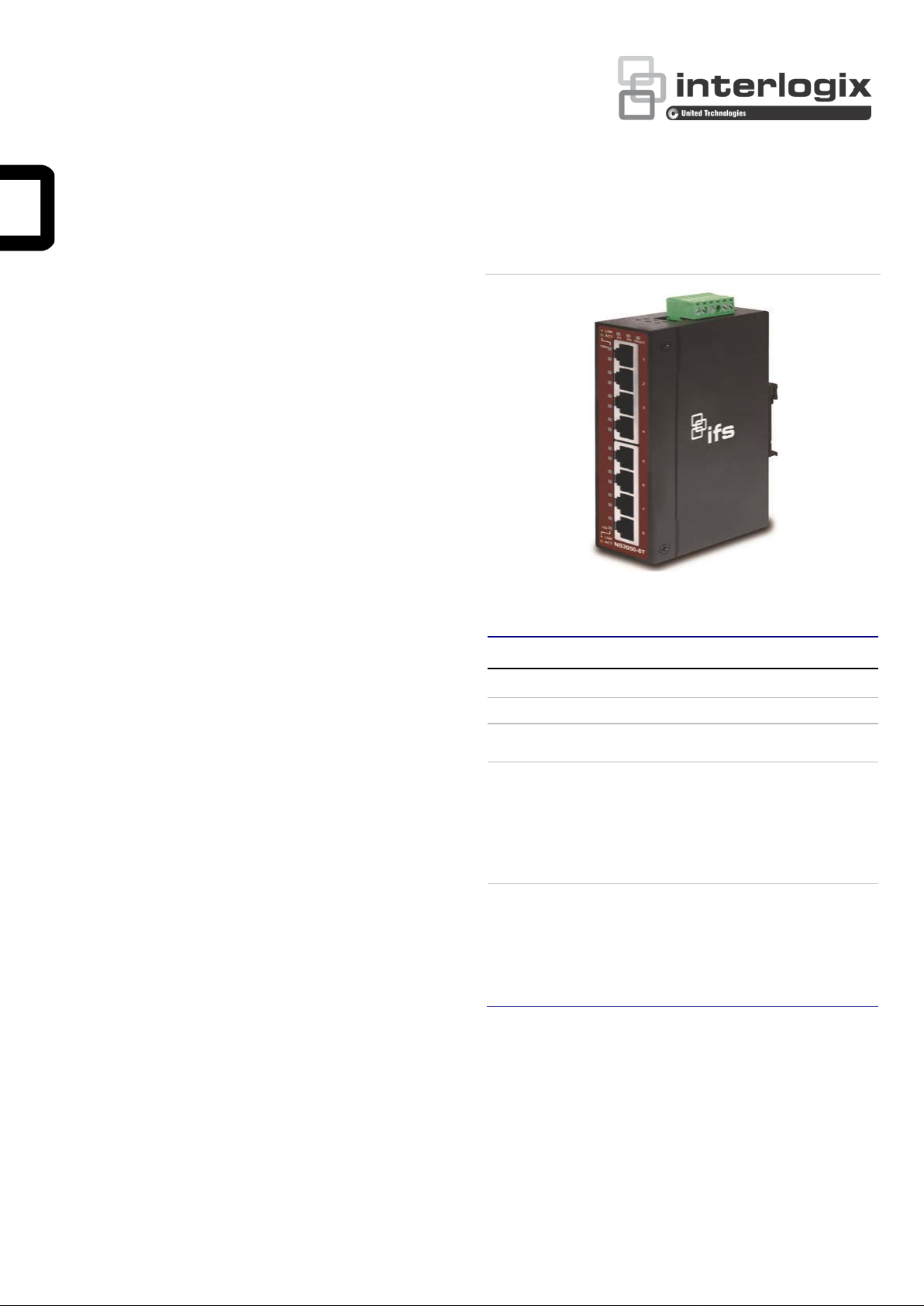
IFS NS3050-8T User Manual
Figure 1: NS3050-8T front panel
Package contents
Thank you for purchasing the NS3050-8T IFS 8-Port
10/100/1000T Industrial Gigabit Ethernet Switch.
Unless specified, the term “industrial gigabit Ethernet
switch” mentioned in this user manual refers to the NS30508T.
Open the box of the industrial gigabit Ethernet switch and
carefully unpack it. The box should contain the following items:
• Industrial gigabit ethernet switch × 1
• CD with user manual × 1
• DIN rail kit × 1
• Wall-mount kit × 1
If any of these are missing or damaged, please contact your
dealer immediately. If possible, retain the carton including the
original packing material, and use them again to repack the
product in case there is a need to return it to us for repair.
Hardware introduction
Physical dimensions
NS3050-8T dimensions (W × D × H): 135 × 87 × 32 mm
See Figure 4 on page 6.
Switch fro n t p anel
The front panel of the industrial gigabit Ethernet switch
consists of five or eight auto-sensing 10/100/1000Mbps
Ethernet RJ45 ports. The LED indicators are also located on
the RJ45 ports of the industrial gigabit Ethernet switch.
LED indicators
LED Color Function
P1 Green Lit: indicates power 1 has power.
P2 Green Lit: indicates power 2 has power.
FAULT Red
1000 Green
100 Orange
Lit: indicates either power 1 or power 2 has
no power.
Lit: indicates the port is successfully
connecting to the network at 1000Mbps.
Off: indicates that the port is successfully
connecting to the network at 10Mbps or
100Mbps.
Blinking: indicates that the port is actively
sending or receiving data.
Lit: indicates the port is successfully
connecting to the network at 100Mbps or
10Mbps.
Off: indicates that the port is successfully
connecting to the network at 1000Mbps.
Blinking: indicates that the port is actively
sending or receiving data.
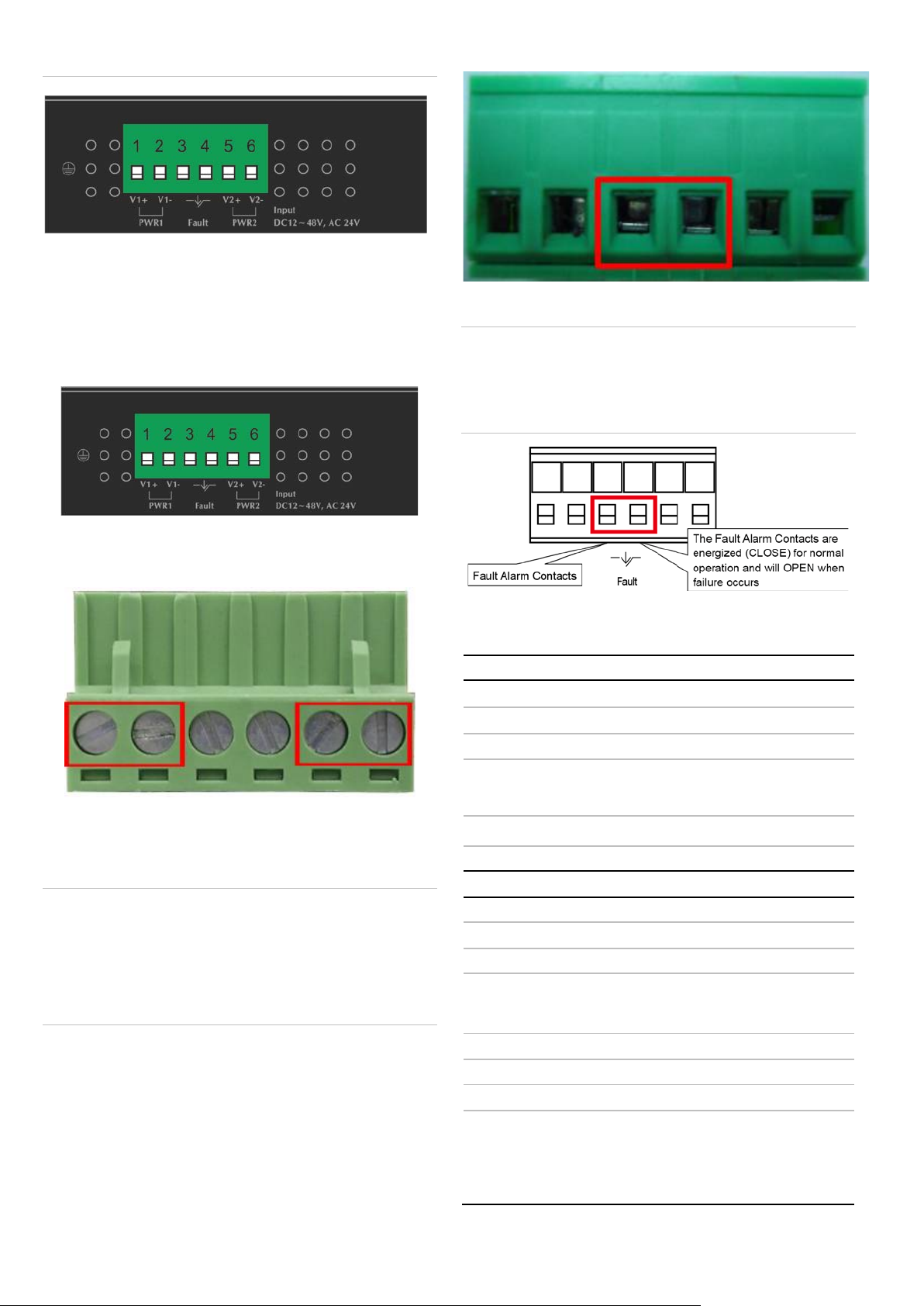
Switch uppe r panel
The upper panel of the industrial gigabit Ethernet switch
consists of one terminal blo ck conn ect or w ithin two DC power
inputs.
Figure 2 on page 2 shows the upper panel of the industrial
gigabit Ethernet switch.
© 2019 United Technologies Corporation. P/N 1073226-EN • REV C • ISS 25JAN19
Interlogix is part of UTC Climate, Controls & Security, a unit of United Technologi es Corporat i on. Al l rights reserved.
1 2 3 4 5
6
Power 1
Fault
Power 2
+ - +
-
1 2 3 4 5
6
8
135
461
12
polarity reverse protection function,
24
n
48
DIN rail kit and wall
Store
4K
1.5
Back pressure for half duplex
IEEE 802.3x
duplex
16
Throughput (packet per second)
11.9
9K
1
Cat3, 4, 5
max.)
EIA/TIA
max.)
Figure 2: Industrial gigabit Etherne t s witch upper panel
Wiring the power inputs
The six-contact terminal bloc k connect or on the top panel of
industrial gigabit Ethernet switch is used for two DC redundant
power inputs. Follow the steps below to insert the power wire.
1. Insert positive and negative DC power wires into contacts
1 and 2 for Power 1 or 5, and 6 for Power 2.
Insert the wires into the fault alarm contacts.
Note:
1. The wire gauge for the terminal block should be in the
range between 12 to 24 AWG.
2. Alarm relay circuit accepts up to 30 V, max. 3 A currents.
V1+ V1 - V2 + V2 -
2. Tighten the wire-clamp screws for preventing the wires
from loosening.
Product specifications
Hardware specifications
10/100/1000BASE-T Ports
Dimensions (W × D × H)
Weight
Note:
1. The wire gauge for the terminal block should be in the
range between 12 and 24 AWG.
Power requirements
Power consumption/ dissipatio
Installation
Switch specifications
Switch processing scheme
Address table
Buffer
2. The device must be grounded.
3. The DC power input range is 12 to 48 VDC.
Flow control
Switch fabric
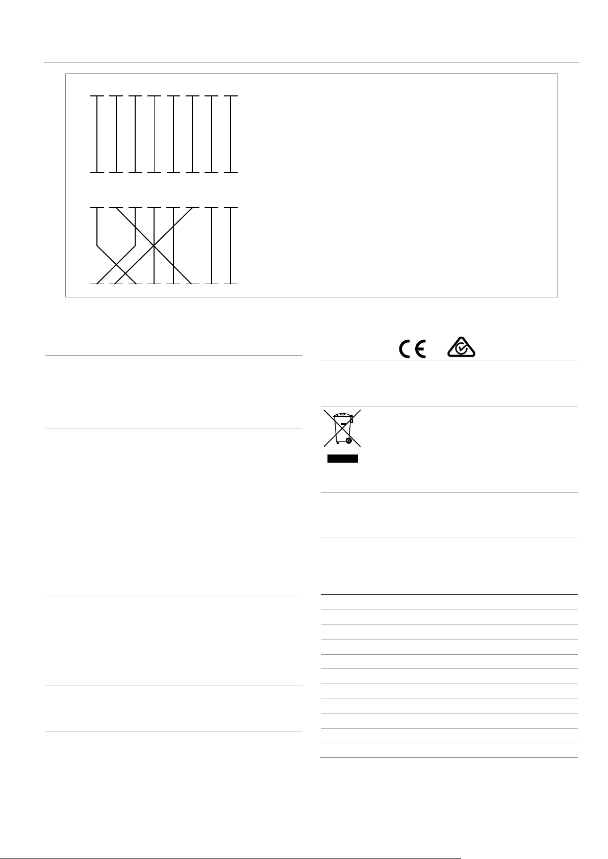
Wiring the fault alarm contact
The fault alarm contacts are in the middle of the terminal block
connector. Upon inserting the w ir es, the industrial gigabit
Ethernet switch detects the fault status of the power failure and
then forms an open circuit. The following illustration shows an
application example for wiring the fault alarm contacts.
2 / 6 P/N 1073226-EN • REV C • ISS 25JAN19
Jumbo frame
Network cables
× 87 × 32 mm
g
to 48 VDC, redundant power with
VAC power support
VDC @ 140 mA 6.72 W / 23 BTU
-mount ear
-and-Forward
Mbits SRAM packet buffer
pause frame for full
Gbps
Mpps
0/100/1000BASE-T:
, 5e, 6 UTP cable (100 m,
-568 100-ohm STP (100 m,

Standards conformance
IEEE 802.3 Ethernet
Standards Compliance
Temperature
Humidity
Regulatory compliance FCC Part 15 Class A, CE
IEEE 802.3u Fast Ethernet
IEEE 802.3ab Gigabit Ethernet
IEEE 802.3x Full-Duplex Flow Control
Operating: -40 to +75°C
Storage: -40 to 75°C
Operating: 5% to 95%, Storage: 5%
to 95% (non-condensing)
Mounting
Note: Ensure that the industrial managed switch is mounted
vertically with the power connectors on the top and a minimum
of three inches above and below the switch to allow for proper
air flow. This device uses a convection flow of hot air which
rises and brings cold air in from the bottom and out of the top
of the device. Do not mount the switch horizontally as this does
not allow air to flow up into the device and will result in damage
to the switch. Do not tie DC1 to DC2. DC2 is for secondary
power redundancy. Do not plug DC power into the device while
the AC power cord is plugged in. This is not a hot-swappable
switch. Hot-swapping this device will result in damage.
3. Ensure that the DIN-rail is secured to the track.
DIN-rail mounting installation
To replace the wall-mount application with DIN-rail application
on industrial gigabit Ethernet switch, refer to the following
figures to screw the DIN-rail on the industrial gigabit Etherne t
switch.
To hang the industrial gigabit Ethernet switch, follow the steps
below:
1. Screw the DIN-rail on the industrial gigabit Ethernet
switch.
2. Place the bottom of DIN-rail lightly into the track.
To remove the industrial gigabit Ethernet switch from the track,
carefully pull out the bottom of the DIN-rail to remove it from
the track.
Wall-mount plate mounting
To install the industrial gigabit Ethernet switch on the wall,
follow the steps below.
1. Remove the DIN-rail from the industrial gigabit Ethernet
switch. Loosen the screws to remove the DIN-rail.
2. Place the wall-mount plate on the rear panel of the
industrial gigabit Ethernet switch.
P/N 1073226-EN • REV C • ISS 25JAN19 3 / 6

Interface
Interface -Cross
3. Use the screws to screw the wall-mount plate on the
industrial gigabit Ethernet switch.
4. Use the hook holes at the corners of the wall-mount plate
to hang the industrial gigabit Ethernet switch on the wall.
5. To remove the wall-mount plate, reverse the steps above.
Troubleshooting
This section contains issue-solving information. If the industrial
gigabit Ethernet switch is not functioning properly, ensure that
the industrial gigabit Ethernet switch was set up according to
instructions in this manual.
Issue Solution
The per port LED does not
illuminate.
Performance is poor
Theper port LED illuminates,
but the traffic is irregular.
The industrial gigabit
Ethernet switch doesn’t
connect to the network
Check the cable connection and
try swapping out a cable.
Check the speed duplex mode of
the partner device. The industrial
gigabit Ethernet switch is run in
auto-negotiation mode and if the
partner is set to half duplex, then
the performance will be poor.
Ensure that the attached device
is not set t o dedicated full duplex.
Some devices use a physical or
software switch to change duplex
modes. Auto-negotiation may not
recognize this type of full-duplex
setting.
Check the per port LED and/or try
another port on the industrial
gigabit Ethernet switch. Ensure
that the cable is installed properly
and is the correct type. Turn off
the power and then, after a while,
turn on the power again.
Appendix: Networking connection
RJ45 pin assignments
1000Mbps, 1000BASE-T
Contact MDI MDI-X
1 BI_DA+ BI_DB+
2 BI_DA- BI_DB3 BI_DB+ BI_DA+
4 BI_DC+ BI_DD+
5 BI_DC- BI_DD6 BI_DB- BI_DA7 BI_DD+ BI_DC+
8 BI_DD- BI_DC-
10/100Mbps, 10/100BASE-TX
MDI
Contact
1 Tx + (transmit) Rx + (receive)
2 Tx - (transmit) Rx - (receive)
3 Rx + (receive) Tx + (transmit)
4, 5 Not used
6 Rx - (receive) Tx - (transmit)
7, 8 Not used
Media Dependent
RJ45 cable pin assignments
The standard RJ45 receptacle/connector
There are eight wires on a standard UTP/STP cable and each
wire is color-coded. Figure 3 on page 5shows the pin allocation
and color of straight-through cable and cro ssover cab le
connection:
MDI-X
Media Dependent
4 / 6 P/N 1073226-EN • REV C • ISS 25JAN19
Straight-through cable
SIDE 1
SIDE 2
SIDE 1
1 = White / Orange
1 = White / Orange
SIDE 2
Crossover cable
SIDE 1
SIDE 2
SIDE 1
1 = White / Orange
1 = White / Green
SIDE 2
Manufacturer
FCC complian ce
generates, uses, and can radiate radio frequency
communications. Operation of this equipment in a
FCC conditions
ACMA compliance
Canada
CAN
Certification
European Union
directives
unsorted municipal waste in the European Union.
Trademarks and
patents
North America
T
E
W
Latin America
T
E
Europe, Middle East, and Africa
W
Australia
E
1 2 3 4 5 6 7 8
1 2 3 4 5 6 7 8
1 2 3 4 5 6 7 8
1 2 3 4 5 6 7 8
Figure 3: Straight-through and crossover cable
2 = Orange
3 = White / Green
4 = Blue
5 = White / Blue
6 = Green
7 = White / Brown
8 = Brown
2 = Orange
3 = White / Green
4 = Blue
5 = White / Blue
6 = Green
7 = White / Brown
8 = Brown
Ensure that the connected cables have the same pin assignment and color as described above.
Regulatory information
Interlogix.
2955 Red Hill Avenue, Costa Mesa, CA 92626
5923, USA
Authorized EU manufacturing representative:
UTC Fire & Security B.V.
Kelvinstraat 7, 6003 DH Weert, The Netherlands
Class A: This equipment has been tested and
found to comply with the limits for a Class A
digital device, pursuant to part 15 of the FCC
Rules. These limits are designed to provide
reasonable protection against harmful
interference when the equipment is operated in a
commercial environment. This equipment
energy and, if not installed and used in
accordance with the instruction manual, may
cause harmful interference to radio
This product complies with the applicable
harmonized European standards listed under the
EMC Directive 2014/30/EU, the RoHS Directive
2011/65/EU.
2012/19/EU (WEEE directive): Products marked
with this symbol cannot be disposed of as
For proper recycling, return this product to your
local supplier upon the purchase of equivalent
new equipment, or dispose of it at designated
collection points. For more information see:
www.recyclethis.info.
The trade names used in this document may be
trademarks or registered trademarks of the
manufacturers or vendors of the respective
products.
2 = Orange
3 = White / Green
4 = Blue
5 = White / Blue
6 = Green
7 = White / Brown
8 = Brown
2 = Green
3 = White / Orange
4 = Blue
5 = White / Blue
6 = Orange
7 = White / Brown
8 = Brown
residential area is likely to cause harmful
interference in which case the user will be
required to correct the interference at his own
expense.
This device complies with Part 15 of the FCC
Rules. Operation is subject to the following two
conditions:
(1) This device may not cause harmful
interference.
(2) This Device must accept any interference
received, including interference that may cause
undesired operation.
P/N 1073226-EN • REV C • ISS 25JAN19 5 / 6
Notice! This is a Class A product. In a domestic
environment this product may cause radio
interference in which case the user may be
required to take adequate measures.
This Class A digital apparatus complies with
ICES-003 (A)/NMB-3 (A).
Cet appareil numérique de la classe A est
conforme à la norme CAN ICES-003 (A)/NMB-3
(A).
Contact information
+1 855.286.8889
techsupport@interlogix.com
www.interlogix.com/support
+1 561-998-6114
latam@interlogix.com
Select Contact Us at www.utcfssecurityproducts.eu
security.tech.support@interlogix.com.au

Physical dimensions
Figure 4: NS3050-8T dimensions (W × D × H): 135 × 87 × 32 mm
6 / 6 P/N 1073226-EN • REV C • ISS 25JAN19
 Loading...