

Page 1

IFS MC252-4P-1S and NS2052-4P-1T User
Manual
Package contents
Unless specified, the term “industrial PoE+ switch”
mentioned in this user manual refers to the MC252-4P-1S and
the NS2052-4P-1T.
Open the box of the industrial PoE+ switch and carefully
unpack it. The box should contain the following items:
• Industrial PoE+ switch × 1
• Dust cap × 4
• Wall-mount kit × 1
If any of these are missing or damaged, please contact your
dealer immediately. If possible, retain the carton including the
original packing material, and use them again to repack the
product in case there is a need to return it to us for repair.
Product features
Physical port
Model Name
NS2052-4P-1T 5 - 4
MC252-4P-1S 4 1 4
10/100 Mbps
RJ45 Ports
100FX SFP
Slots
PoE Ports
Power over Ethernet
• Complies with IEEE 802.3at Power over Ethernet Plus,
end-span PSE
• Backward compatible with IEEE 802.3af Power over
Ethernet
• Up to four ports of IEEE 802.3af/at devices powered
• Up to 120 W PoE budget
• Supports PoE power up to 36 W for each PoE port
• Each port supports 54 VDC power to PoE powered device
• Auto detects powered device (PD)
• Circuit protection prevents power interference between
ports
• Remote power feeding up to 100 m in standard mode with
250 m in extend mode (switch selectable)
Switching
• Hardware-based 10/100 Mbps (half/full duplex), autonegotiation, and auto MDI/MDI-X
• Features Store-and-Forward mode with wire-speed
filtering and forwarding rates
• IEEE 802.3x flow control for full duplex operation and back
pressure for half duplex operation
• 2K MAC address table size
Interface
• NS2052-4P-1T: Four 10/100BASE-TX Fast Ethernet IEEE
802.3at PoE+ RJ45 copper ports (Port-1 to Port-4)
• MC252-4P-1S: Four 10/100BASE-TX Fast Ethernet RJ45
copper ports with IEEE 802.3at PoE+ Injector (Port-1 to
Port-4)
• NS2052-4P-1T:One 10/100BASE-TX Fast Ethernet nonPoE RJ45 copper port.
• MC252-4P-1S: One 100BASE-FX SFP interface
• One terminal block for master and slave power input
(Power Range: 12~48 VDC redundant power).
• Hardware DIP switch for Standard, VLAN, and Extend
mode selection; the Extend mode features a 25 W PoE
transmission distance of 250 m at a speed of 10 Mbps
(Port-1 to Port-4 only).
© 2019 United Technologies Corporation. P/N 1073625-EN • REV A • ISS 17APR19
Interlogix is part of UTC Climate, Controls & Security, a unit of United Technologies Corporation. All rights reserved. All trademarks are the property
of their respective owners. Information in this document is subject to change without notice.
• 10K jumbo frame
• IEEE 802.1Q VLAN transparency
• Automatic address learning and address aging
• Supports CSMA/CD protocol
Industrial case and installation
• IP40 metal case
• DIN-rail, wall-mount design
• 12~48 VDC redundant power with polarity reverse protect
function
• Fault alarm for power input failed
• Supports 5 KV DC Ethernet ESD protection
• -40 to 75°C operating temperature
• Four real-time PoE power usage indicators
Page 2
DIP Switch Mode
the
,
Product description
Cost-effective full PoE+ power solution ideal for hardened
environment
Featuring Plug and Play designed to be installed in heavy
industrial demanding environments, the industrial PoE+
switches are industrial-grade, DIN-rail type unmanaged Fast
Ethernet PoE+ switches with four 10/100BASE-TX PoE+ ports,
with one additional Fast Ethernet (NS2052-4P-1T) or
100BASE-FX fiber optic (MC252-4P-1S) interface for video
uplink. The industrial PoE+ switches are designed with a
redundant power system and operate reliably, stably, and
quietly in any hardened environment without affecting
performance. It comes with a total power budget of up to 120
W for different kinds of PoE applications and an operating
temperature ranging from -40 to 75°C in a rugged IP40 metal
housing.
Extension of ethernet data transmission distance
The industrial PoE+ switch has a built-in solid DIP switch
providing Standard, VLAN, and Extend operation modes. By
default, the industrial PoE+ switch operates as a normal IEEE
802.3af/at PoE+ switch in the “Standard” operation mode.
The "VLAN" operation mode features with port-based VLAN
function helps to prevent the IP camera’s multicast or
broadcast storm from influencing each other.
In the “Extend” operation mode, the industrial PoE+ switch
operates on a per-port basis at 10 Mbps full duplex operation
and can support 25 W PoE power output over a distance of up
to 250 meters, overcoming the 100-meter limit on Ethernet
UTP cable.
Convenient and reliable power system
To facilitate the 802.3at PoE+ usage with commonly used
12~48V DC power input for transportation and industrial-lev el
applications, the industrial PoE+ switch adopts 12~48 VDC to
54V power boost technology to solve power source issues but
does not require special power supplies. The industrial PoE+
switch provides an integrated power solution with a wide range
of voltages (12~48 VDC) for worldwide operability. It also
provides dual-redundant, reversible polarity 12~48 VDC power
supply inputs for high availability applications.
Environmentally hardened design
With the IP40 metal industrial case, the industrial PoE+ switch
provides a high level of immunity against electromagnetic
interference and heavy electrical surges which are usually
found on plant floors or in curb-side traffic control cabinets
without air conditioning. It features a ventilated construction in
which a cooling fan is not necessary, thereby making its
operation noiseless. Being able to operate under the
temperature range from -40 to 75°C, the industrial PoE+ switch
can be placed in almost any difficult environment.
Robust protection
The industrial PoE+ switch provides contact discharge of ±5
KV DC and air discharge of ±5 KV DC for Ethernet ESD
protection. It also supports ±5 KV surge immunity to improve
product stability and protects users’ networks from devastating
ESD attacks, making sure the flow of operation does not
fluctuate.
Hardware introduction
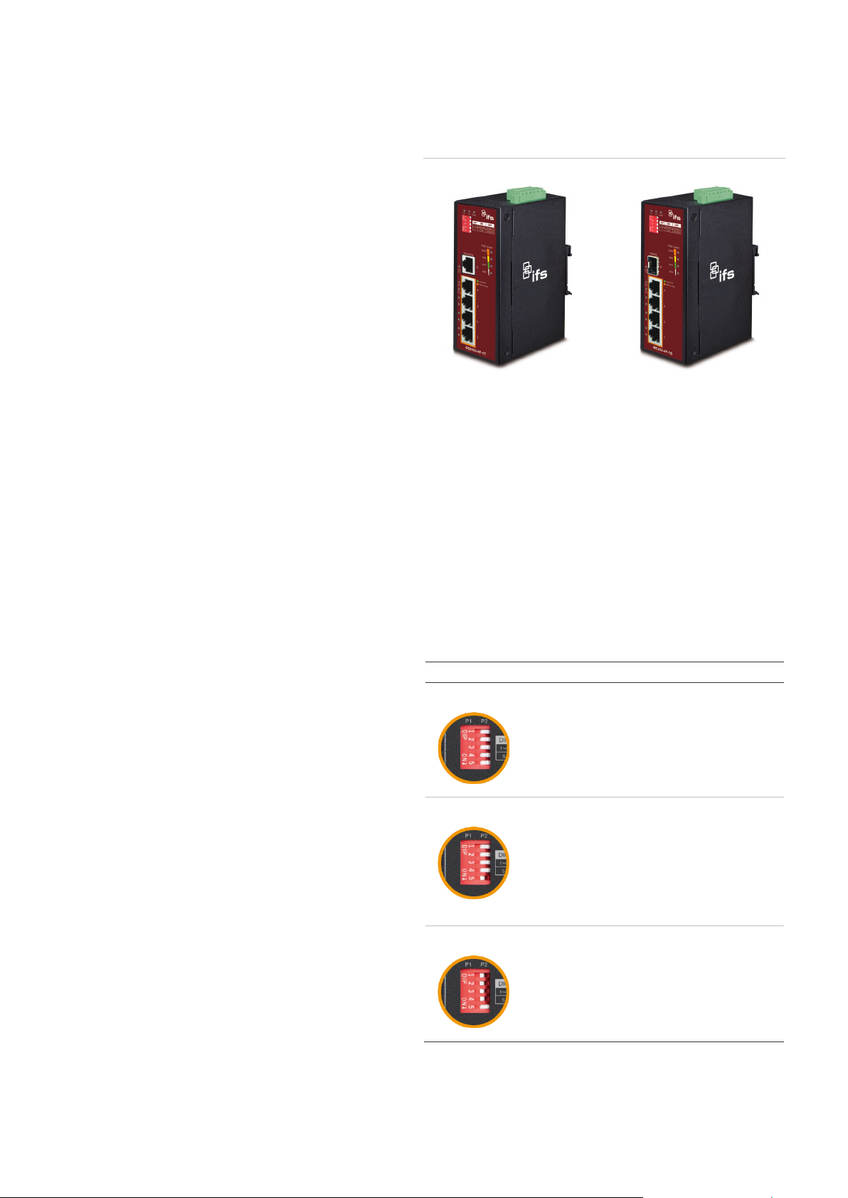
Switch front panel
Figure 1: Industrial PoE+ switch front panels
NS2052-4P-1T
Fast Ethernet TP interfaces
10/100BASE-TX copper, RJ45 twisted-pair: Up to 100 meters.
100BASE-FX SFP slot (MC252-4P-1S)
100BASE-FX mini-GBIC slot, SFP (Small Factor Pluggable)
transceiver module: From 2 kilometers (multi-mode fiber) to
20/40/60 kilometers (single-mode fiber).
DIP switch
The industrial PoE+ switch provides one DIP switch for
Standard, VLAN, and Extended mode selections. The detailed
descriptions are shown in the following table.
Function
Standard
In this mode, the industrial PoE+ switch operates
as a general switch and all PoE ports operate at
10/100Mbps auto-negotiation.
VL AN
Extended
In this mode, the industrial PoE+ switch operates
as a VLAN isolation switch and
1. Port 1 to port 4 will isolate respectively.
2. Port 1 to port 4 can only communicate with
port 5.
Note: After adjusting the VLAN DIP switch,
reboot the industrial PoE+ switch to effectuate
change.
In this mode, the industrial PoE+ switch operates
on a per-port basis at 10 Mbps full duplex
operation but can support IEEE 802.3af PoE
power output over a distance of up to 250 meters
overcoming the 100 m limit on a Ethernet UTP
cable.
MC252-4P-1S
2 / 9 P/N 1073625-EN • REV A • ISS 17APR19
Page 3
1 2 3 4 5
6
Power 1
Fault
Power 2
+ - +
-
LED indicators
System
LED Color Function
P1 Green Lit: indicates power 1 has power.
P2 Green Lit: indicates power 2 has power.
FAULT Red
30W Orange
60W Orange
90W Orange
120W Orange
Lit: indicates either power 1 or power 2 has
no power.
Off: indicates the PoE usage is less than 14
W.
Blinking: indicates that the PoE usage is
around 15 to 29 W.
Lights: indicates the PoE usage is
around/over 30 W.
Blinking: indicates that the PoE usage is
around 45 to 59 W.
Lit: indicates the PoE usage is around/over
60 W.
Blinking: indicates that the PoE usage is
around 75 to 89 W.
Lit: indicates the PoE usage is around/over
90 W.
Blinking: indicates that the PoE usage is
around 100 to 119 W.
Lit: indicates the PoE usage is at the
maximum.
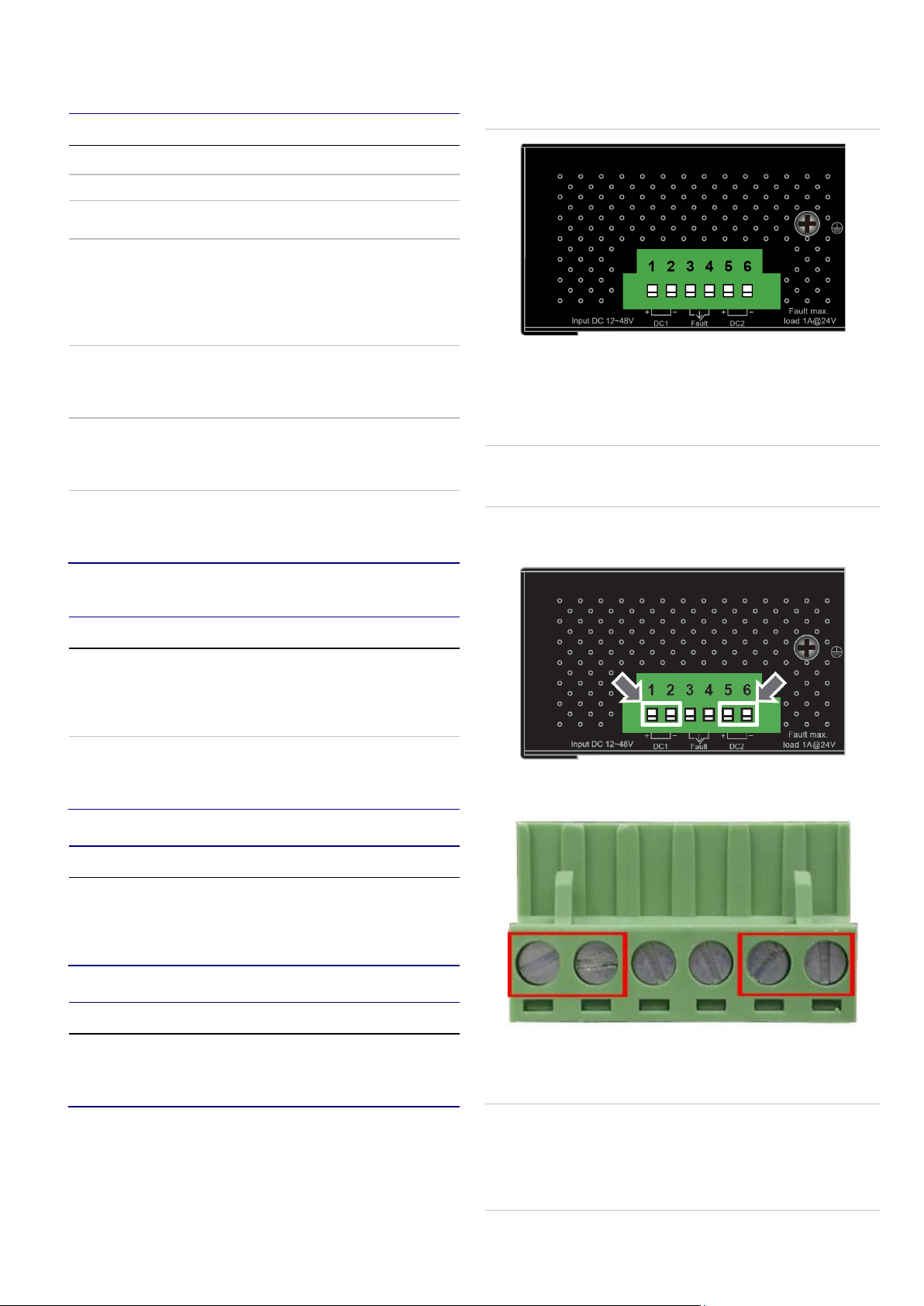
Figure 2 below shows the upper panel of the industrial PoE+
switch.
Figure 2: Industrial PoE+ switch upper panel
Wiring the power inputs
The six-contact terminal block connector on the top panel of
industrial PoE+ switch is used for two DC redundant power
inputs. Follow the steps below to insert the power wire.
Caution: When performing procedures like inserting the wires
or tightening the wire-clamp screws, ensure that the power is
OFF to prevent electrical shock.
1. Insert positive and negative DC power wires into contacts
1 and 2 for Power 1 or 5, and 6 for Power 2.
Per 802.3at PoE+ 10/100BASE-TX Interface (Port 1 to Port
4)
LED Color Function
Link/ACT Green
PoE in
Use
Orange
Lit: indicates the port is successfully
connecting to the network at 10 Mbps or
100 Mbps.
Blinking: indicates that the port is actively
sending or receiving data.
Lit: indicates the port is providing DC in-line
power.
Off: indicates the connected device is not a
PoE powered device (PD).
Per 10/100BASE-TX Interface (Port 5 of NS2052-4P-1T)
LED Color Function
Link/ACT Green
Lit: indicates the port is successfully
connecting to the network at 10 or 100
Mbps.
Blinking: indicates that the port is actively
sending or receiving data.
Per 100FX SFP Slot (Port 5 of MC252-4P-1S)
LED Color Function
Link/ACT Green
Lit: indicates the port is successfully
connecting to the network at 100 Mbps.
Blinking: indicates that the port is actively
sending or receiving data.
2. Tighten the wire-clamp screws for preventing the wires
from loosening.
Notes:
Switch upper panel
The upper panel of the industrial PoE+ switch consists of one
terminal block connector within two DC power inputs.
P/N 1073625-EN • REV A • ISS 17APR19 3 / 9
1. The wire gauge for the terminal block should be in the
range between 12 and 24 AWG.
2. The DC power input range is 12 to 48 VDC.
Page 4

1 2 3 4 5
6
3. When the DC power input range is 12 V, the PoE budget is
60 W;
When the DC power input range is 24 V, the PoE budget is
90 W;
When the DC power input range is 48 V, the PoE budget is
120 W.
To avoid damage, use the industrial PoE+ switch under its
specification.
Wiring the fault alarm contact
The fault alarm contacts are in the middle of the terminal block
connector. Upon inserting the wires, the industrial PoE+ switch
detects the fault status of the power failure and then forms an
open circuit. The following illustration shows an application
example for wiring the fault alarm contacts.
DIN-rail mounting installation
To replace the wall-mount application with DIN-rail application
on the industrial PoE+ switch, refer to the following figures to
screw the DIN-rail on the industrial PoE+ switch.
To hang the industrial PoE+ switch, follow the steps below:
1. Screw the DIN-rail on the industrial PoE+ switch.
2. Place the bottom of DIN-rail lightly into the track.
Insert the wires into the fault alarm contacts.
Note:
1. The wire gauge for the terminal block should be in the
range between 12 to 24 AWG.
2. Alarm relay circuit accepts up to 24 V, max. 1 A currents.
Mounting
Note: Ensure that the industrial PoE+ switch is mounted
vertically with the power connectors on the top and a minimum
of three inches above and below the switch to allow for proper
air flow. This device uses a convection flow of hot air which
rises and brings cold air in from the bottom and out of the top
of the device. Do not mount the switch horizontally as this does
not allow air to flow up into the device and will result in damage
to the switch. Do not tie DC1 to DC2. DC2 is for secondary
power redundancy. Do not plug DC power into the device while
the AC power cord is plugged in. This is not a hot-swappable
switch. Hot-swapping this device will result in damage.
3. Ensure that the DIN-rail is secured to the track.
To remove the industrial PoE+ switch from the track, carefully
pull out the bottom of the DIN-rail to remove it from the track.
4 / 9 P/N 1073625-EN • REV A • ISS 17APR19
Page 5

X ports
based VLAN Protection" where
Extend mode: 25 W PoE transmission distance of
Wall-mount plate mounting
To install the industrial PoE+ switch on the wall, follow the
steps below.
1. Remove the DIN-rail from the industrial PoE+ switch.
Loosen the screws to remove the DIN-rail.
2. Place the wall-mount plates on the rear panel of the
industrial PoE+ switch as shown below.
3. Use the screws to screw the wall-mount plates on the
industrial PoE+ switch.
4. Use the hook holes at the corners of the wall-mount plates
to hang the industrial PoE+ switch on the wall.
5. To remove the wall-mount plates, reverse the steps
above.
Installation Steps
This section describes the functionalities of the Industrial PoE+
components and guides how to install it on the desktop. Basic
knowledge of networking is assumed. Please read this chapter
completely before installation.
1. Unpack the industrial PoE+ switch.
Please refer to the LED indicators section for LED
definitions.
8. When all connections are set up and the LEDs illuminate,
the installation is complete.
Troubleshooting
This section contains issue-solving information. If the industrial
PoE+ switch is not functioning properly, ensure that the
industrial PoE+ switch was set up according to instructions in
this manual.
Issue Solution
The per port LED does
not illuminate.
Performance is poor
The per port LED
illuminates, but the
traffic is irregular.
The industrial PoE+
switch doesn’t
connect to the network
Check the cable connection and try
swapping out a cable.
Check the speed duplex mode of the
partner device. The industrial PoE+
switch is run in auto-negotiation mode
and if the partner is set to half duplex,
then the performance will be poor.
Ensure that the attached device is not
set to dedicated full duplex. Some
devices use a physical or software
switch to change duplex modes. Autonegotiation may not recognize this type
of full-duplex setting.
Check the per port LED and/or try
another port on the industrial PoE+
switch. Ensure that the cable is installed
properly and is the correct type. Turn off
the power and then, after a while, turn
on the power again.
Product specifications
2. Check the DIN-Rail that is pre-installed on the industrial
PoE+ switch. (Please refer to DIN-Rail Mounting section
for DIN-Rail installation. If you want to wall mount the
industrial PoE+ switch, then please refer to Wall Mount
Plate Mounting section for specific instructions.
3. To hang the industrial PoE+ switch on the DIN-Rail track
or wall, please refer to the Mounting section.
4. Power on the industrial PoE+ switch. (Please refer to the
Wiring the Power Inputs section for power input) The
power LED on the industrial PoE+ switch illuminates.
Please refer to the LED indicators section for LED
definitions.
5. Prepare the twisted-pair, straight through Category 5 cable
for Ethernet connection.
6. Insert one side of Category 5 cables into the industrial
PoE+ switch Ethernet port (RJ-45 port) and the other side
to the network device Ethernet port (RJ-45 port), ex:
Switch, PC, or Server. The UTP port (RJ-45) LED on the
industrial PoE+ switch illuminates when the cable is
connected to the network device. Please refer to the LED
indicators section for LED definitions.
7. Insert the fiber cable from the industrial PoE+ switch to the
fiber network. TX, RX must be paired at both ends. The
optical port LED on the MC252-4P-1S illuminates when
the connection is established with a network device.
MC252-4P-1S
Hardware specifications
Fast Ethernet
Copper Ports
PoE Injector Port
SFP Port One 100BASE-FX SFP port
Switch Architecture Store-and-Forward
Switch Fabric 1 Gbps/non-blocking
Switch
Throughput@64
bytes
MAC Address
Table
Flow Control
Jumbo Frame 10 Kbytes
DIP Switch (Port-1
to Port-4)
Four 10/100BASE-TX RJ45 auto-MDI/MDI-
Four ports with 802.3af/at PoE+ injector function
(Port-1 to Port-4)
0.74 Mpps @64 bytes
2K entries
IEEE 802.3x pause frame for full-duplex
Back pressure for half-duplex
Standard mode: 30 W PoE transmission distance
of 100 m at speed of 10/100 Mbps.
VLAN mode: "Port-
ports can be isolated from each other via one DIP
switch. Only Port-5 can visit other ports.
P/N 1073625-EN • REV A • ISS 17APR19 5 / 9
Page 6

250 m at a speed of 10 Mbps (switch selectable).
D
IEEE 802.3at Power over Ethernet Plus
X ports
based VLAN Protection" where
D
Removable 6-pin terminal block:
Connector
Alarm
Power
requirements
Power
Consumption/
Dissipation
Dimensions (W ×
× H)
Weight 598 g
ESD protection 5 KV DC
Enclosure IP40 metal case
Installation DIN rail kit and wall-mount ear
Power over Ethernet
PoE Standard IEEE 802.3at Power over Ethernet Plus / PSE
PoE Power Supply
Type
Power Pin
Assignment
PoE Power Output 54 VDC Per Port, Max. 36 W
PoE Power Budget
(max.)
Max. Number of
Class 2 PDs
Max. Number of
Class 3 PDs
Max. Number of
Class 4 PDs
Standards conformance
Regulatory
compliance
Stability testing
Standards
Compliance
Pin 1/2 for Power 1
Pin 3/4 for power fault alarm
Pin 5/6 for Power 2
One relay output for power failure.
Alarm relay current carry ability: 1 A @ 24 VAC
12 to 48 VDC, 7 A (max.)
4.3 W, 14.6 BTU (Standby without PoE function)
at DC 12 V power input
72.5 W, 247.4 BTU (Full loading with PoE
function) at DC 12 V power input
5 W, 17 BTU (Standby without PoE function) at
DC 24 V power input
103.9 W, 354.5 BTU (Full loading with PoE
function) at DC 24 V power input
5.3 W, 18.1 BTU (Standby without PoE function)
at DC 48V power input
135.8 W, 463.4 BTU (Full loading with PoE
function) at DC 48 V power input
50 × 85.1 × 135 mm
End-Span
1/2(+), 3/6(-)
60 W @ 12 VDC input
90 W @ 24 VDC input
120 W @ 48 VDC input
4
4
4
FCC Part 15 Class A, CE
IEC60068-2-32 (Free Fall)
IEC60068-2-27 (Shock)
IEC60068-2-6 (Vibration)
IEEE 802.3 10BASE-T
IEEE 802.3u 100BASE-TX
IEEE 802.3ab Gigabit 1000BASE-T
IEEE 802.3z Gigabit SX/LX
IEEE 802.3x Flow Control and Back Pressure
IEEE 802.3af Power over Ethernet
Environment
Temperature
Humidity 5% to 95% (non-condensing)
Operating: -40 to +75°C
Storage: -40 to 85°C
NS2052-4P-1T
Hardware specifications
Fast Ethernet
Copper Ports
PoE Injector Port
Switch Architecture Store-and-Forward
Switch Fabric 1 Gbps/non-blocking
Switch
Throughput@64
bytes
MAC Address
Table
Flow Control
Jumbo Frame 10 Kbytes
DIP Switch (Port-1
to Port-4)
Connector
Alarm
Power
requirements
Power
Consumption/
Dissipation
Dimensions (W ×
× H)
Weight 596 g
ESD protection 5 KV DC
Enclosure IP40 metal case
Installation DIN rail kit and wall-mount ear
Five 10/100BASE-TX RJ45 auto-MDI/MDI(Port-1 to Port-5)
Four ports with 802.3af/at PoE+ injector function
(Port-1 to Port-4)
0.74 Mpps @64 bytes
2K entries
IEEE 802.3x pause frame for full-duplex
Back pressure for half-duplex
Standard mode: 30 W PoE transmission distance
of 100 m at speed of 10/100 Mbps.
VLAN mode: "Port-
ports can be isolated from each other via one DIP
switch. Only Port-5 can visit other ports.
Extend mode: 25 W PoE transmission distance of
250 m at a speed of 10 Mbps (switch selectable).
Removable 6-pin terminal block:
Pin 1/2 for Power 1
Pin 3/4 for power fault alarm
Pin 5/6 for Power 2
One relay output for power failure.
Alarm relay current carry ability: 1 A @ 24 VAC
12 to 48 VDC, 7 A (max.)
3.7 W, 12.6 BTU (Standby without PoE function)
at DC 12 V power input
70 W, 238.8 BTU (Full loading with PoE function)
at DC 12 V power input
4.6 W, 15.7 BTU (Standby without PoE function)
at DC 24 V power input
105.1 W, 358.6 BTU (Full loading with PoE
function) at DC 24 V power input
4.8 W, 16.4 BTU (Standby without PoE function)
at DC 48V power input
136.8 W, 466.8 BTU (Full loading with PoE
function) at DC 48 V power input
50 × 85.1 × 135 mm
6 / 9 P/N 1073625-EN • REV A • ISS 17APR19
Page 7

Power over Ethernet
PoE Standard IEEE 802.3at Power over Ethernet Plus / PSE
PoE Power Supply
Type
Power Pin
Assignment
PoE Power Output 54 VDC Per Port, Max. 36 W
PoE Power Budget
(max.)
Max. Number of
Class 2 PDs
Max. Number of
Class 3 PDs
Max. Number of
Class 4 PDs
Standards conformance
Regulatory
compliance
Stability testing
Standards
Compliance
Environment
Temperature
Humidity 5% to 95% (non-condensing)
End-Span
1/2(+), 3/6(-)
60 W @ 12 VDC input
90 W @ 24 VDC input
120 W @ 48 VDC input
4
4
4
FCC Part 15 Class A, CE
IEC60068-2-32 (Free Fall)
IEC60068-2-27 (Shock)
IEC60068-2-6 (Vibration)
IEEE 802.3 10BASE-T
IEEE 802.3u 100BASE-TX
IEEE 802.3ab Gigabit 1000BASE-T
IEEE 802.3x Flow Control and Back Pressure
IEEE 802.3af Power over Ethernet
IEEE 802.3at Power over Ethernet Plus
Operating: -40 to +75°C
Storage: -40 to 85°C
Appendix: Networking connection
RJ45 pin assignments
1000Mbps, 1000BASE-T
Contact MDI MDI-X
1 BI_DA+ BI_DB+
2 BI_DA- BI_DB-
3 BI_DB+ BI_DA+
4 BI_DC+ BI_DD+
5 BI_DC- BI_DD-
6 BI_DB- BI_DA-
7 BI_DD+ BI_DC+
8 BI_DD- BI_DC-
10/100Mbps, 10/100BASE-TX
MDI
Contact
1 Tx + (transmit) Rx + (receive)
2 Tx - (transmit) Rx - (receive)
3 Rx + (receive) Tx + (transmit)
4, 5 Not used
6 Rx - (receive) Tx - (transmit)
7, 8 Not used
Media Dependent
Interface
RJ45 cable pin assignments
MDI-X
Media Dependent
Interface-Cross
The standard RJ45 receptacle/connector
There are eight wires on a standard UTP/STP cable and each
wire is color-coded. Figure 3 on page 8 shows the pin
allocation and color of straight-through cable and crossover
cable connection:
P/N 1073625-EN • REV A • ISS 17APR19 7 / 9
Page 8

Straight-through cable
SIDE 1
SIDE 2
SIDE 1
1 = White / Orange
1 = White / Orange
SIDE 2
Crossover cable
SIDE 1
SIDE 2
SIDE 1
1 = White / Orange
1 = White / Green
SIDE 2
Disclaimer
Trademarks and
patents
may be
Product warnings
and disclaimers
rs and
C
information and
manuals/
firmware
are, go to the web
Manufacturer
FCC compliance
communications. Operation of this equipment in a
FCC conditions
ACMA compliance
1 2 3 4 5 6 7 8
1 2 3 4 5 6 7 8
1 2 3 4 5 6 7 8
1 2 3 4 5 6 7 8
Figure 3: Straight-through and crossover cable
2 = Orange
3 = White / Green
4 = Blue
5 = White / Blue
6 = Green
7 = White / Brown
8 = Brown
2 = Orange
3 = White / Green
4 = Blue
5 = White / Blue
6 = Green
7 = White / Brown
8 = Brown
2 = Orange
3 = White / Green
4 = Blue
5 = White / Blue
6 = Green
7 = White / Brown
8 = Brown
2 = Green
3 = White / Orange
4 = Blue
5 = White / Blue
6 = Orange
7 = White / Brown
8 = Brown
Ensure that the connected cables have the same pin assignment and color as described above.
Regulatory information
8 / 9 P/N 1073625-EN • REV A • ISS 17APR19
Information in this document is subject to change
without notice. No part of this document may be
reproduced or transmitted in any form or by any
means, electronic or mechanical, for any
purpose, without the express written permission
of UTC Fire & Security Americas Corporation, Inc
The TruVision Navigator name and logo are
trademarks of United Technologies.
Other trade names used in this document
trademarks or registered trademarks of the
manufacturers or vendors of the respective
products.
THESE PRODUCTS ARE INTENDED FOR
SALE TO AND INSTALLATION BY QUALIFIED
PROFESSIONALS. UTC FIRE & SECURITY
CANNOT PROVIDE ANY ASSURANCE THAT
ANY PERSON OR ENTITY BUYING ITS
PRODUCTS, INCLUDING ANY “AUTHORIZED
DEALER” OR “AUTHORIZED RESELLER”, IS
PROPERLY TRAINED OR EXPERIENCED TO
CORRECTLY INSTALL FIRE AND SECURITY
RELATED PRODUCTS.
For more information on warranty disclaime
product safety information, please check
www.firesecurityproducts.com/policy/product-
warning/ or scan the following code:
ontact
tools/
For contact information and to download the
latest manuals, tools, and firmw
site of your region.
Americas: www.interlogix.com
EMEA: www.firesecurityproducts.com
Manuals are available in several languages.
Australia/New Zealand: www.utcfs.com.au
Interlogix.
2955 Red Hill Avenue, Costa Mesa, CA 92626
5923, USA
Authorized EU manufacturing representative:
UTC Fire & Security B.V.
Kelvinstraat 7, 6003 DH Weert, The Netherlands
Class A: This equipment has been tested and
found to comply with the limits for a Class A
digital device, pursuant to part 15 of the FCC
Rules. These limits are designed to provide
reasonable protection against harmful
interference when the equipment is operated in a
commercial environment. This equipment
generates, uses, and can radiate radio frequency
energy and, if not installed and used in
accordance with the instruction manual, may
cause harmful interference to radio
residential area is likely to cause harmful
interference in which case the user will be
required to correct the interference at his own
expense.
This device complies with Part 15 of the FCC
Rules. Operation is subject to the following two
conditions:
(1) This device may not cause harmful
interference.
(2) This Device must accept any interference
received, including interference that may cause
undesired operation.
Notice! This is a Class A product. In a domestic
environment this product may cause radio
interference in which case the user may be
required to take adequate measures.
Page 9

Canada
This Class A digital apparatus complies with CAN
Certification
European Union
directives
.
North America
T
E
W
Latin America
T
E
Europe, Middle East, and Africa
W
Australia
E
ICES-003 (A)/NMB-3 (A).
Cet appareil numérique de la classe A est
conforme à la norme CAN ICES-003 (A)/NMB-3
(A).
This product complies with the applicable
harmonized European standards listed under the
EMC Directive 2014/30/EU, the RoHS Directive
2011/65/EU.
2012/19/EU (WEEE directive): Products marked
with this symbol cannot be disposed of as
unsorted municipal waste in the European Union
For proper recycling, return this product to your
local supplier upon the purchase of equivalent
new equipment, or dispose of it at designated
collection points. For more information see:
www.recyclethis.info.
Contact information
+1 855.286.8889
techsupport@interlogix.com
www.interlogix.com/support
+1 561-998-6114
latam@interlogix.com
Select Contact Us at www.firesecurityproducts.com
security.tech.support@interlogix.com.au
P/N 1073625-EN • REV A • ISS 17APR19 9 / 9
 Loading...