

Page 1
Wireless Rate-of-Rise Heat Sensor Installation Instructions
Introduction
The Interlogix HDX series wireless heat sensors use
electronic processing to detect both heat and freeze
conditions using a learn mode wireless transmitter all in one
unit. The micro-processor trips the transmitter when the
temperature at the sensor location reaches a fixed
temperature of 135°F (57°C), 200°F (94°C), 41°F (5°C),
depending on the model installed, or senses a rate of rise at
12°F to 15ºF (6.7 to 8.3ºC)
Figure 1
Models
HDX-135 Wireless 135°F (57°C) Rate-of-Rise Heat
Sensor
HDX-200 Wireless 200°F (93°C) Rate-of-Rise Heat
Sensor
HDX-135Z * Wireless 135°F (57°C) Rate-of-Rise Heat &
Freeze Sensor
* The HDX-135Z sensor has two independent ID #’s for heat and
freeze, the sensor will alarm at a fixed 135°F (57°C) temperature
or a 12° to 15ºF (6.7 to 8.3ºC) rate of rise, or when the sensor
reaches 41°F (5°C), the sensor will restore at 50°F (10ºC).
Installation
Use the following installation guidelines:
• Heat sensors should be installed to provide property
protection. Reliance should not be placed on heat
sensors for life safety. Where life safety is involved,
smoke sensors must also be installed.
• The sensors allow for normal temperature fluctuations,
however, ceiling temperatures should not exceed 100°F
(38°C)
• Mount the sensor in a central location of the area to be
protected, either on the ceiling or on a wall.
• If mounting on a ceiling, the sensor must be at least 4 in.
(10 cm) away from any walls.
• The UL maximum spacing allowance of the sensor is 50
x 50 ft. (15 x 15 m). Refer to the NFPA Standard 72 for
application requirements.
• Do not mount the sensor close to devices that change
temperature rapidly, such as ovens, heat vents,
furnaces, or boilers.
Enrolling
The panel must learn (program) the sensor ID codes in order to
respond to sensor signals. For complete programming information,
refer to the specific control panel documentation.
Note: The HDX-135Z sensor has two ID numbers, one for heat the
other for freeze. Each number is programmed separately.
To add the sensor to panel memory:
1. Place the panel in program mode.
2. Proceed to the Learn Sensors menu. When the panel
prompts you for a sensor group number, with Simon
XT/XTi, Concord, and Advisor panels program the zone
to use sensor group 26. With NetworX and Ultrasync
panels program the zone to use sensor group 8.
3. Select the desired sensor number. When the panel
prompts you to trip the sensor, remove and reinsert the
battery (or remove battery pull tab) until the panel
beeps, indicating successful programming.
4. When programming for the HDX-135Z model for freeze
detection remain in program mode.
Simon XT/XTi, Concord, and Advisor panels
select sensor group 29.
NetworX panels program the zone to use sensor
group 22.
Ultrasync panels program sensor type to “24-
Hour Audible” and sensor option to “Low Temp”.
Also check box for “Disable Internal Reed”.
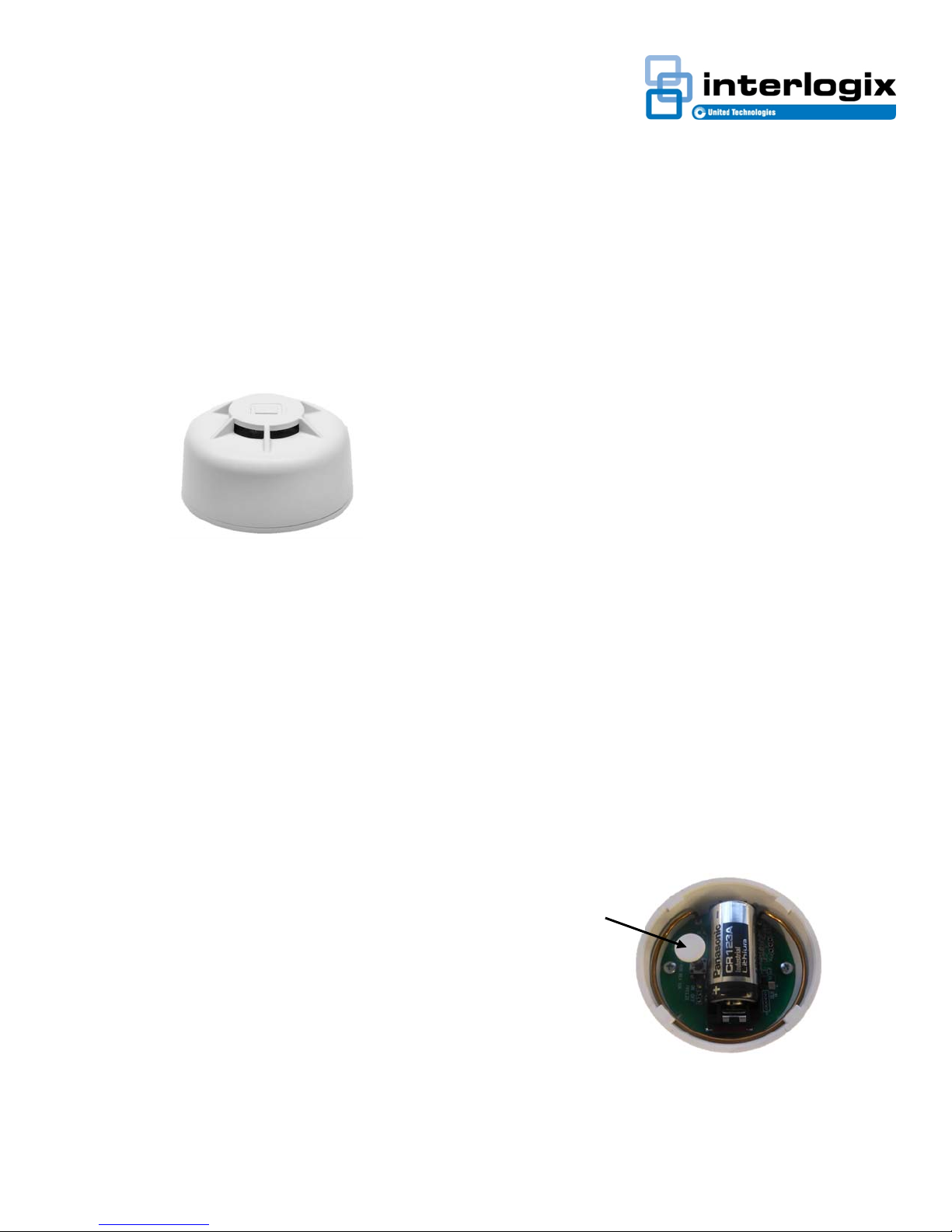
5. Hold down the tamper switch (Figure 2), then remove
and reinsert the battery to learn in the freeze portion of
the sensor.
Tamper
• If mounting on a wall, the top of the sensor must be
within 4 to 6 in. (10 to 15 cm) of the ceiling.
466-5244 • REV A • 25MAY16 1
6. Exit Program Mode
Figure 2: Tamper
Page 2
Mounting the Sensor
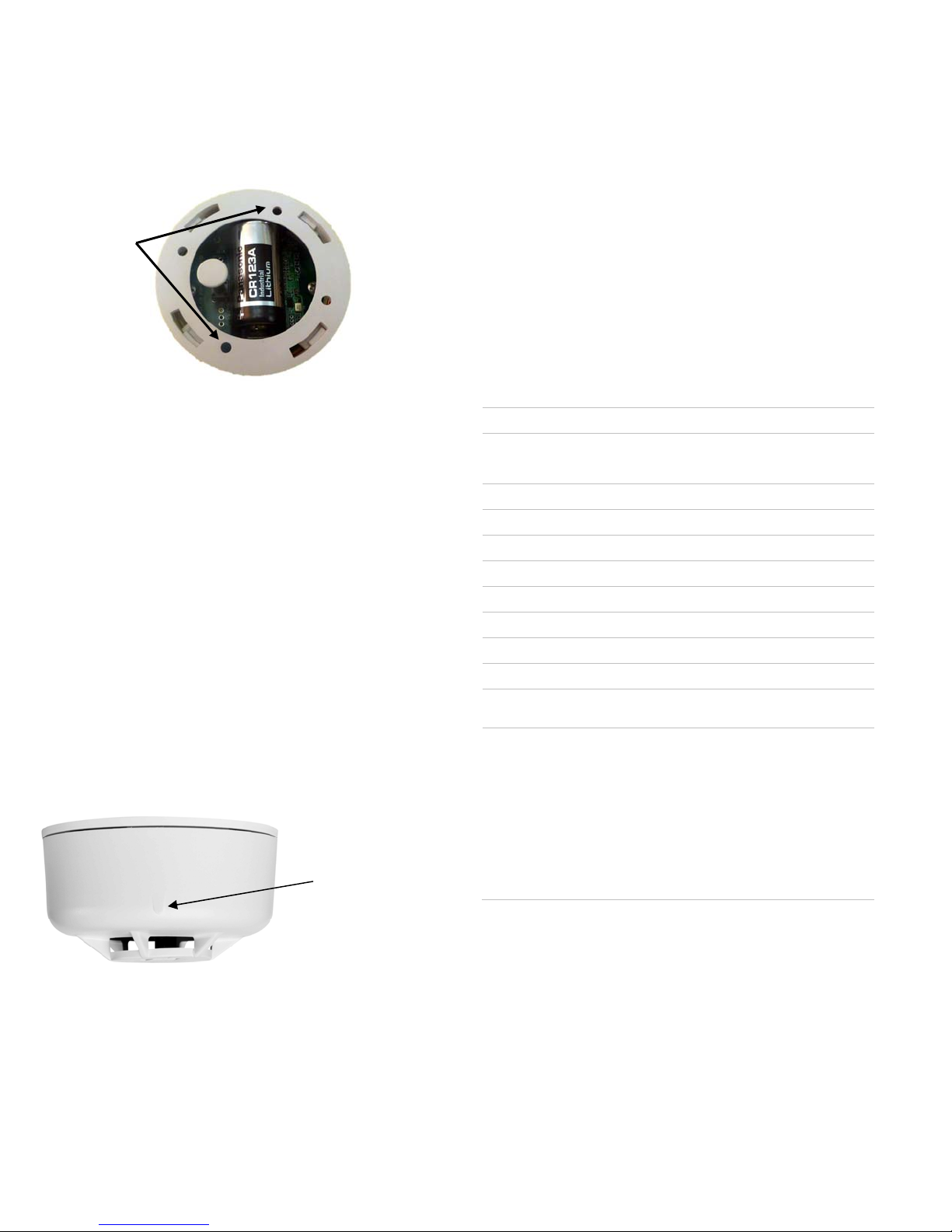
1. Locate the base mounting holes and mount the base to
the wall or ceiling with the appropriate hardware (Figure
3)
2. Attach the sensor to the mounting base
Mounting
Holes
Figure 3: Mounting Holes
Testing
1. Before permanently securing the sensor to the wall or
ceiling, test the sensor from the installation location
using one of the following methods.
2. Place the panel in sensor test mode.
3. Plug in a portable hair dryer.
4. Hold the hair dryer about 12 to 18 in. away from the
sensor, aiming it at the side of the sensor.
5. Listen for the appropriate number of beeps from interior
sirens and speakers (refer to the specific panel
documentation).
6. To test the freeze sensor, use either freeze spray or
place an ice cube in a plastic bag and hold against the
sensor until the device trips.
7. Listen for the appropriate number of beeps from interior
sirens and speakers
Magnet Test
Note: Notify central station before any live testing to avoid fire
response. The magnet test allows the sensor to send an actual
alarm signal to the control panel, if a magnet is held against the
housing for 15 seconds.
Magnet Mark
and Location
Figure 4: Magnet Mark
1. With the sensor permanently mounted, place a magnet
against the mark located on the sensor body. (Figure 4)
2. Hold the magnet in place for about 15 seconds
3. The control panel should respond by sounding the fire
alarm (Heat and Freeze Alarm)
4. Disarm control panel to silence alarm
Replacing the Batteries
Battery life depends on how often the sensor transmits
signals, but is more dependent on the temperature of the
installation environment. When the battery voltage gets low,
the sensor transmits a low battery signal to the panel. The
panel then activates trouble beeps to notify the customer
that the sensor battery must be replaced. Pressing the
Status button identifies the sensor with the low battery.
Replace the battery immediately when this condition occurs,
using the following battery: Panasonic CR123A 3V
Battery Disposal
The batteries used in this sensor are lithium batteries and
are not reusable. Be sure to properly dispose of used lithium
batteries according to your local hazardous waste disposal
laws.
Specifications
Minimum Rate of Rise rating 12° to 15ºF (6.7° to 8.3C)
Operating temperature
UL max. Ambient ceiling 100°F/150°F (37.8ºC / 65.6ºC)
Storage Temperature -30 to 167°F (-34 to 75°C)
Relative Humidity 0 to 95% noncondensing
Detection range up to 2500 sq. ft.
Frequency 319.5 MHz (crystal-controlled)
Expected Battery Life 10 years
Standby Current Less than 0.9 µA
Supervision Interval 62-68 minutes
Enclosure Dimensions
Regulatory
135°F (57°C): 32 - 100°F (0 - 37°C)
200°F (94°C): 32 - 150°F (0 - 66°C)
Diameter: 2.29" (58.25mm)
Height: 1.28" (32.4mm)
UL 521 Heat Detectors for Fire
Protective Signaling Systems
UL 985 Household Fire Warning
System Units
CAN/ULC-S530 Heat Actuated Fire
Detectors for Fire Alarm Systems
CSFM Category 7270
FCC: 15.109 Class B, 15.231
Industry Canada: ICES-003, RSS210
Contact Information
Visit us online at www.interlogix.com.
For technical support, see www.interlogix.com/support
Product Ordering
Model
HDX-135 Wireless 135°F (57°C) Rate-of-Rise Heat
Sensor
HDX-200 Wireless 200°F (93°C) Rate-of-Rise Heat
Sensor
HDX-135Z Wireless 135°F (57°C) Rate-of-Rise Heat &
Freeze Sensor
2 466-5244 • REV A • 25MAY16
Page 3

FCC / IC Statement
This equipment has been tested and found to comply with the limits
for a Class B digital device, pursuant to Part 15 of the FCC Rules.
These limits are designed to provide reasonable protection against
harmful interference in a residential installation.
This equipment generates, uses and can radiate radio frequency
energy and, if not installed and used in accordance with the
instructions, may cause harmful interference to radio
communications. However, there is no guarantee that interference
will not occur in a particular installation.
If this equipment does cause harmful interference to radio or
television reception, which can be determined by turning the
equipment off and on, the user is encouraged to try to correct the
interference by one or more of the following measures:
• Reorient or relocate the receiving antenna.
• Increase the separation between the equipment and receiver.
• Connect the equipment into an outlet on a circuit different from
that to which the receiver is connected.
• Consult the dealer or an experienced radio/TV technician for
help.
Changes or modifications not expressly approved by UTC Fire and
Security could void the user’s authority to operate the equipment.
This device complies with Industry Canada licence-exempt RSS
standard(s). Operation is subject to the following two conditions: (1)
this device may not cause interference, and (2) this device must
accept any interference, including interference that may cause
undesired operation of the device.
Cet appareil est conforme avec Industrie Canada exempts de
licence standard RSS (s). Son fonctionnement est soumis aux deux
conditions suivantes: (1) cet appareil ne doit pas provoquer
d'interférences et (2) cet appareil doit accepter toute interférence, y
compris celles pouvant causer un mauvais fonctionnement de
l'appareil.
In accordance with FCC requirements of human exposure to radio
frequency fields, the radiating element shall be installed such that a
minimum separation distance of 20 cm is maintained from the
general population.
FCC: Place ID number here
IC: Place ID number here
This Class B digital apparatus complies with Canadian ICES-3B.
Cet appareil numérique de la classe B est conforme à la norme
NMB-003 du Canada.
Copyright
Copyright © 2016 United Technologies Corporation.
All rights reserved.
Trademarks
Interlogix is a registered trademark of United Technologies
Corporation. Interlogix is part of UTC Climate, Controls & Security, a
unit of United Technologies Corporation.
MANUFACTURER HEREBY DISCLAIMS ALL WARRANTIES AND
REPRESENTATIONS, WHETHER EXPRESS, IMPLIED,
STATUTORY OR OTHERWISE INCLUDING (BUT NOT LIMITED
TO) ANY WARRANTIES OF MERCHANTABILITY OR FITNESS
FOR A PARTICULAR PURPOSE WITH RESPECT TO THESE
PRODUCTS AND ANY RELATED SOFTWARE.
MANUFACTURER FURTHER DISCLAIMS ANY OTHER IMPLIED
WARRANTY UNDER THE UNIFORM COMPUTER
INFORMATION TRANSACTIONS ACT OR SIMILAR LAW AS
ENACTED BY ANY STATE.
(USA only) SOME STATES DO NOT ALLOW THE EXCLUSION
OF IMPLIED WARRANTIES, SO THE ABOVE EXCLUSION MAY
NOT APPLY TO YOU. THIS WARRANTY GIVES YOU SPECIFIC
LEGAL RIGHTS AND YOU MAY ALSO HAVE OTHER LEGAL
RIGHTS THAT VARY FROM STATE TO STATE.
MANUFACTURER MAKES NO REPRESENTATION,
WARRANTY, COVENANT OR PROMISE THAT ITS ALARM
PRODUCTS AND/OR RELATED SOFTWARE (I) WILL NOT BE
HACKED, COMPROMISED AND/OR CIRCUMVENTED; (II)
WILL PREVENT, OR PROVIDE ADEQUATE WARNING OR
PROTECTION FROM, BREAK-INS, BURGLARY, ROBBERY,
FIRE; OR (III) WILL WORK PROPERLY IN ALL
ENVIRONMENTS AND APPLICATIONS.
466-5244 • REV A • 25MAY16 3
 Loading...