

Page 1
Tamper
HDX-135-345 Wireless Rate-of-Rise Heat Sensor Installation Instructions
Introduction
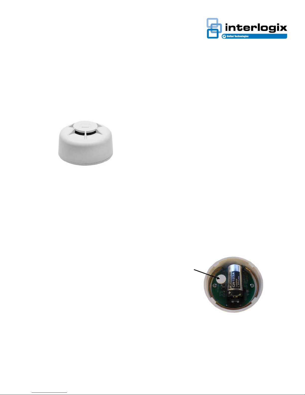
The Interlogix HDX series wireless heat detectors use
electronic processing to detect temperature Rate-of-Rise
and fixed heat set point conditions plus a learn mode
wireless transmitter in one unit. The micro-processor trips
the transmitter when the temperature at the detector location
reaches a fixed temperature of 135°F (57°C) or senses a
rate of rise at 12°F to 15ºF (6.7 to 8.3ºC)
Figure 1
Model
HDX-135-345 Wireless 135ºF (57ºC) Rate-of-Rise Heat
Sensor, 345 MHz Wireless, Compatible with
Honeywell and 2GIG Wireless Receivers
Installation
Use the following installation guidelines:
• Heat detectors should be installed to provide property
protection. Reliance should not be placed on heat
sensors for life safety. Where life safety is involved,
smoke sensors must also be installed.
• The detectors allow for normal temperature fluctuations,
however, ceiling temperatures should not exceed 100°F
(38°C)
• Mount the detector in a central location of the area to be
protected, either on the ceiling or on a wall.
• If mounting on a ceiling, the detect or must be at least 4
in. (10 cm) away from any walls.
• If mounting on a wall, the top of the detector must be
within 4 to 6 in. (10 to 15 cm) of the ceiling.
• The UL maximum spacing allowance of the detector is
50 x 50 ft. (15 x 15 m). Refer to the NFPA Standard 72
for application requirements.
• Do not mount the detector close to devices that change
temperature rapidly, such as ovens, heat vents,
furnaces, or boilers.
Enrolling
The HDX-135-345 is compatible with Honeywell and 2GIG
wireless receivers. These panels must learn (program) the
detector ID codes in order to respond to detector signals. For
complete programming instructions refer to the specific
control panel instruction guides.
To add the sensor to panel memory:
Honeywell™
The HDX-135-345 must be enrolled in the control panel
before it can operate in the system . The heat protect ion zone
must be enrolled as Loop 1 and “Input Type” 3 (supervised
RF). Tamper is transmitted as Loop 4, but does not require
programming.
1. Place the panel in program mode.
2. Enter the zone number to be programmed.
3. Enter the zone type when prompted. Program as a Fire
zone type [9]
4. When prompted, enter Input Type [03] (3 on some
panels) – Supervised RF Transmitter
5. Remove pull tab from sensor battery
6. When prompted for the serial number, transmit from the
detector by activating (press and release) the tamper
switch (Figure 2).
7. When serial number is displayed, transmit from sensor
again by activating tamper switch again. The current
loop number will begin to flash (4).
8. Manually change the loop number to loop number [1].
Note: The fire protection zone enrolled must always be
Loop 1. Otherwise, fire annunciations will not be
reported by the control
9. Exit programming when complete. Test the sensor after
enrolling into the system. Refer to the Testing section in
this guide.
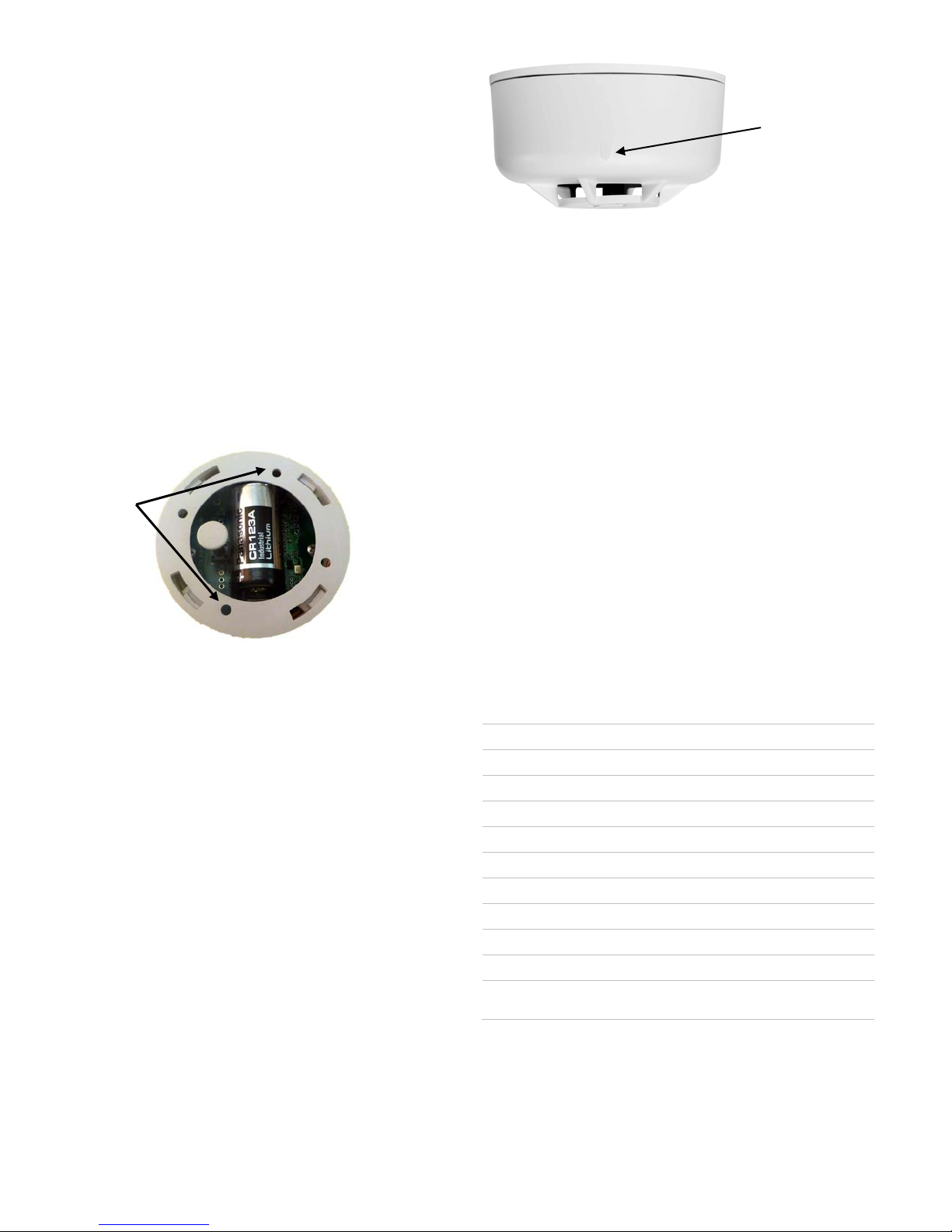
Figure 2: Tamper
2GIG®
The following procedure describes how to learn-in the HDX135-345 heat sensor into the 2GIG control panel.
1. Select RF sensor #(01 to 48)
2. Select RF sensor type [09] Smoke/Heat
3. Select RF sensor equipment code. Enter code 0895
466-5304 • REV A • 20January17 1
Page 2
4. With panel in learn-in mode (press Shift then Learn)
Rate of Rise rating
Operating temperature
UL max. Ambient ceiling
Storage
Relative H
Maximum UL Spacing
Frequency
E
S
Supervision I
Enclosure D
Magnet Mark
and Location
Mounting
Holes
cause a tamper by pressing and then release tamper
switch (Figure 2). The correct TX ID should appear.
Accept by pressing OK.
5. Select RF sensor equipment age [0] New
6. Select RF sensor loop number [1]
7. Select dialer delay (enable/disable)
8. Select voice descriptors (see panel manual)
9. Select sensor reports (enable/disable)
10. Select sensor chime
11. To exit programming, click skip
12. Click end and exit. The panel takes a few seconds to
reset.
Mounting the Detector
1. Locate the base mounting holes and mount the base to
the wall or ceiling with the appropriate hardware (Figure
3)
2. Attach the detector to the mounting bas e
Figure 4: Magnet Mark
1. With the sensor permanently mounted, place a magnet
against the mark located on the sensor body. (Figure 4)
2. Hold the magnet in place for about 15 seconds
3. The control panel should respond by sounding the fire
alarm
4. Disarm control panel to silence alarm
Replacing the Batteries
Battery life depends on how often the detector transmits
signals, but is more dependent on the temperature of the
installation environment. When the battery voltage gets low,
the detector transmits a low battery signal to the panel. The
panel then activates trouble beeps to notify the customer
that the detector battery must be replaced. Pressing the
status button identifies the sensor with the low battery.
Figure 3: Mounting Holes
Testing
1. Before permanently securing the detector to the wall or
ceiling, test the detector from the installation location
using one of the following methods.
2. Place the panel in sensor test mode.
3. Plug in a portable hair dryer.
4. Hold the hair dryer about 12 to 18 in. away from the
sensor, aiming it at the side of the sensor.
5. Listen for the appropriate number of beeps from interior
sirens and speakers (refer to the specific panel
6. Listen for the appropriate number of beeps from interior
sirens and speakers
Magnet Test
Note: Notify central station before any live testing to avoid fire
response. The magnet test allows the sensor to send an actual
alarm signal to the control panel, if a magnet is held against the
housing for 15 seconds.
Replace the battery immediately when this condition occurs,
using the following battery: Panasonic CR123A 3V
Battery Disposal
The batteries used in this sensor are lithium batteries and
are not reusable. Be sure to properly dispose of used lithium
batteries according to your local hazardous waste disposal
laws.
Specifications
12° to 15ºF (6.7° to 8.3C)
135°F (57°C): 32 - 100°F (0 - 37°C)
100°F (37.8ºC )
Temperature -30 to 167°F (-34 to 75°C)
umidity 0 to 95% noncondensing
50ft (15.2m) x 50ft (15.2m)
345 MHz (crystal-controlled)
xpected Battery Life 10 years
tandby Current Less than 0.9 µA
nterval 62-68 minutes
imensions
Diameter: 2.29" (58.25mm)
Height: 1.28" (32.4mm)
2 466-5304 • REV A • 20January17
Page 3

Regulatory
210
UL 521 Heat Detectors for Fire
Protective Signaling Systems
UL 985 Household Fire Warning
System Units
CAN/ULC-S530 Heat Actuated Fire
Detectors for Fire Alarm Systems
CSFM Category 7270
FCC: 15.109 Class B, 15.231
Industry Canada: ICES-003, RSS-
Contact Information
Visit us online at www.interlogix.com.
For technical support, see www.interlogix .com/support
Product Ordering
Model
HDX-135-345 Wireless 135ºF (57ºC) Rate-of-Rise Heat
Sensor, 345 MHz Wireless, Compatible with
Honeywell and 2GIG Wireless Receivers
Recommendation to Installer
Annual inspection and testing by a qualified technician of the
rate-of-rise heat sensor is recommended to maintain
satisfactory functionality of the sensor. Visual inspection of
the unit should occur onc e per week to ensure proper
operation.
FCC / IC Statement
This equipment has been tested and found to comply with the limits
for a Class B digital device, pursuant to Part 15 of the FCC Rules.
These limits are designed to provide reasonable protection against
harmful interference in a residential installation.
This equipment generates uses and can radiate radio frequency
energy and, if not installed and used in accordance with the
instructions, may cause harmful interference to radio
communications. However, there is no guarantee that interference
will not occur in a particular installation.
If this equipment does cause harmful interference to radio or
television reception, which can be determined by turning the
equipment off and on, the user is encouraged to try to correct the
interference by one or more of the following measures:
• Reorient or relocate the receiving antenna.
• Increase the separation between the equipment and receiver.
• Connect the equipment into an outlet on a circuit different from
that to which the receiver is connected.
• Consult the dealer or an experienced radio/TV technician for
help.
Changes or modifications not expressly approved by UTC Fire and
Security could void the user’s authority to operate the equipment.
This device complies with Industry Canada licence-exempt RSS
standard(s). Operation is subject to the following two conditions: (1)
this device may not cause interference, and (2) this device must
accept any interference, including interference that may cause
undesired operation of the device.
Cet appareil est conforme avec Industrie Canada exempts de
licence standard RSS (s). Son fonctionnement est soumis aux deux
conditions suivantes: (1) cet appareil ne doit pas provoquer
d'interférences et (2) cet appareil doit accepter toute interférence, y
compris celles pouvant causer un mauvais fonctionnement de
l'appareil.
In accordance with FCC requirements of human exposure to radio
frequency fields, the radiating element shall be installed such that a
minimum separation distance of 20 cm is maintained from the
general population.
FCC: 2ABBZ-RF-ROR-345
IC: 11817A-RFROR345
This Class B digital apparatus complies with Canadian ICES-3B.
Cet appareil numérique de la classe B est conforme à la norme
NMB-003 du Canada.
Copyright
Copyright © 2016 United Technologies Corporation.
All rights reserved.
Trademarks
Interlogix is a registered trademark of United T echnologies
Corporation. Interlogix is part of UTC C limate, Contr ols & S ecurity , a
unit of United Technologies Corporation.
MANUFACTURER HEREBY DISCLAIMS ALL WARRANTIES AND
REPRESENTATIONS, WHETHER EXPRESS, IMPLIED,
STATUTORY OR OTHERWISE INCLUDING (BUT NOT LIMITED
TO) ANY WARRANTIES OF MERCHANTABILITY OR FITNESS
FOR A PARTICULAR PURPOSE WITH RESPECT TO THESE
PRODUCTS AND ANY RELATED SOFTWARE.
MANUFACTURER FURTHER DISCLAIMS ANY OTHER IMPL IED
WARRANTY UNDER THE UNIFORM COMPUTER
INFORMATION TRANSACTIONS ACT OR SIMILAR LAW AS
ENACTED BY ANY STATE.
(USA only) SOME STATES DO NOT ALLOW THE EXCLUSION
OF IMPLIED WARRANTIES, SO THE ABOVE EXCLUSION MAY
NOT APPLY TO YOU. THIS WARRANTY GIVES YOU SPECIFIC
LEGAL RIGHTS AND YOU MAY ALSO HAVE OTHER LEGAL
RIGHTS THAT VARY FROM STATE TO STATE.
MANUFACTURER MAKES NO REPRESENTATION,
WARRANTY, COVENANT OR PROMISE THAT ITS ALARM
PRODUCTS AND/OR RELATED SOFTWARE (I) WILL NOT BE
HACKED, COMPROMISED AND/OR CIRCUMVENTED; (II)
WILL PREVENT, OR PROVIDE ADEQUATE WARNING OR
PROTECTION FROM, BREAK-INS, BURGLARY, ROBBERY,
FIRE; OR (III) WILL WORK PROPERLY IN ALL
ENVIRONMENTS AND APPLICATIONS.
466-5304 • REV A • 23February17 3
 Loading...