

Page 1

IFS GE-DSH-73/82 and
82-POE Managed Switch
Installation Sheet
Package Contents
Thank you for purchasing the IFS 7/8-Port Fast Ethernet + 2/3-Port Gigabit
TP/SFP Combo Managed Switch. The following Managed Switch model
numbers are covered in this sheet:
• GE-DSH-73
• GE-DSH-82
• GE-DSH-82-PoE
Open the b
contain the following items:
• The Managed Switch x1
• User manual CD x1
• This Installation Sheet x1
• RJ-45 to RS-232 cable x1
If any item is found missing or damaged, please contact your local reseller
for replacement.
© 2010 UTC Fire & Security.
All rights reserved.
P/N 1069666-EN • REV 1.01 •
ISS 14JUL10 1 of 13
ox of the Managed Switch and carefully unpack it. The box should
Page 2

System Requirements
Your switch is designed to operate with a variety of platforms, operating
systems and network cards. Actual performance will depend on a
combination of these components. Differences in performance can occur
depending on the versions and types of platforms, operating system and
network cards used.
The minimum system requirements are:
• Clients running Windows 98/ME, NT4.0, 2000/XP, Vista, MAC OS9 or
later, Linux, UNIX or other platform compatible with TCP/IP protocols.
• Workstation installed with Ethernet NIC (Network interface Card)
• Serial Port connection (Terminal)
• Above PC with COM Port (DB-9)
• Ethernet Port connection
• Network cables - Use standard network (UTP) cables with RJ45
connectors
• Above PC installed with WEB Browser and JAVA runtime
environment Plug-in
Note: We recommend using Windows XP or Windows 7 with Internet
Explorer 6.0 or above for access to the switch management setup.
Wiring the Power Units
The 6-contact terminal block connector on the top panel of Managed
Industrial Switch is used for two DC redundant power inputs.
Note: This product is intended to be supplied by a UL Listed Direct Plug-In
Power Unit marked "Class 2" or "LPS" and output rated 48 VDC, 380 mA
minimum.
Please follow the steps below to insert the power wire.
1. Insert the positive/negative DC power wires into the contacts 1 and 2 for
POWER 2, or 5 and 6 for POWER 1.
2 of 13 P/N 1069666-EN • REV 1.01 • ISS 14JUL10
Page 3
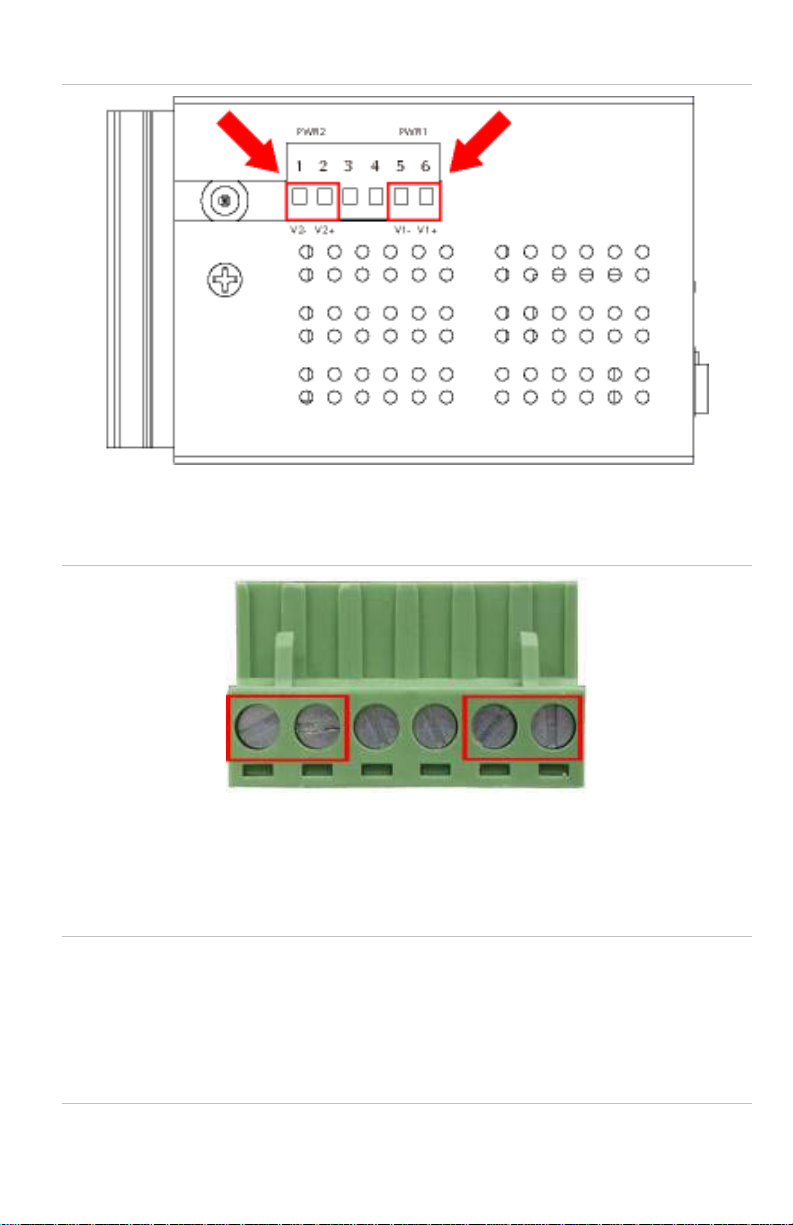
1: Terminal block connectors
Figure
2. Tighten the wire-clamp screws to prevent the wires from loosening.
Figure 2: Terminal block pinouts
1 2 3 4 5 6
Power 2 Power 2
- + - +
Note: The wire gauge for the terminal block should be in the range between
12 to 24 AWG.
For the GE-DSH-82-PoE, A 48VDC, 3A power input is required for full PoE
load on the PoE. Please connect an external power source to the terminal
block that can supply steady power at 48VDC.
P/N 1069666-EN • REV 1.01 • ISS 14JUL10 3 of 13
Page 4
Terminal Setup
There are three ways to access and setup your switch. They are:
• RS-232 console
• Telnet
• Web Browser
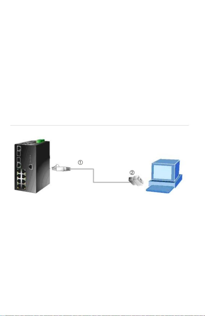
RS-232 console
To configure the system, connect a serial cable to a COM port on a PC or
notebook computer and to the serial (console) port of the GE-DSH-82
Managed Switch. The console port of the Managed Switch is DCE already so
that you can connect the console port directly through PC without the need of
a Null Modem.
Figure 3: Terminal setup diagram
Managed Industrial Switch
RJ-45 Type Serial Port 9600,8,n,1 PC / Workstation with Terminal emulation
1. RJ-45 to DB9 RS-232 cable
2. Serial port
software
A terminal program is required to make the software connection to the GEDSH-73, GE-DSH-82 and the GE-DSH-82-PoE Managed Switch. Window’s
Hyper Terminal program is a good choice. Hyper Terminal program can be
accessed from the Start menu.
1. Click START, then Programs/ Accessories and then Hyper Terminal.
2. When the following screen appears, make sure that the COM port is
configured as follows:
4 of 13 P/N 1069666-EN • REV 1.01 • ISS 14JUL10
Page 5

• Baud : 9600
• Parity : None
• Data bits : 8
• Stop bits : 1
• Flow Control : None
Figure 4: COM1 properties window
Logon to the Console
Once the terminal has connected to the device, power on the GE-DSH-73,
GE-DSH-82 and the GE-DSH-82-PoE Managed Switch. The terminal will
display that it is running testing procedures.
Then, the following message asks for the login user name and password.
The factory default password for the login screen is:
• Username: admin
• Password: admin
P/N 1069666-EN • REV 1.01 • ISS 14JUL10 5 of 13
Page 6

Figure 5: GE-DS
H-73, GE-DSH-82 and the GE-DSH-82-PoE Login screen
Note: For security reasons, please change and memorize the new password
after this first setup. Passwords must be entered in lowercase letters in the
console interface.
Configure IP Address
The Managed Industrial Switch is shipped with default IP address as follows:
IP Address: 192.168.0.100
Subnet Mask: 255.255.255.0
To check the current IP address or modify a new IP address for the Managed
Industrial Switch, please use the procedures as follows:
Show the current IP address
1. On the "Switch>" prompt, enter "enable" to enter Privileged EXEC mode.
2. On the "Switch #" prompt, enter "show ip".
3. The screen displays the current IP address, Subnet Mask and Gateway.
As shown in Figure 6.
6 of 13 P/N 1069666-EN • REV 1.01 • ISS 14JUL10
Page 7

6: IP information screen
Figure
Configure IP address
1. On the "Switch# " prompt, type "configure" to enter the configuration
mode.
2. On the "Switch(config)# " prompt, enter the following command and
press <Enter>. As show in Figure 7.
Switch(config)# ip address 192.168.1.100 255.255.255.0 192.168.1.1
The previous command will apply the follow settings for the Managed
Industrial Switch.
• IP: 192.168.1.100
• Subnet Mask: 255.255.255.0
• Gateway: 192.168.1.1
P/N 1069666-EN • REV 1.01 • ISS 14JUL10 7 of 13
Page 8

Figure 7:
Set IP address screen
3. Repeat Step 2 to check if the IP address is changed.
If the IP is successfully configured, the Managed Industrial Switch will apply
the new IP address setting immediately. You can access the Web interface
of Managed Industrial Switch through the new IP address.
Note: If you are not familiar with console command or the related parameter,
enter "?" anytime in console to get the help description.
Telnet Setup
1. Connect an RJ-45 cable from the PC to a Switch port on the Managed
Switch.
8 of 13 P/N 1069666-EN • REV 1.01 • ISS 14JUL10
Page 9

Figure 8:
PC/Workstation with IE Browser Managed Industrial Switch
RJ-45 connection diagram
IP Address: 192.168.0.x IP Address: 192.168.0.100
1. RJ645 /UTP Cable
2. Enable the Hyper Terminal program. A terminal program is required
to make the software connection to the Managed Switch. Windows'
Hyper Terminal program is a good choice. Hyper Terminal can be
accessed from the Start menu. Click START, then Programs,
Accessories and then Hyper Terminal.
3. The following screen will appear. Enter a new connection name. You
should use something like the model name of your switch.
Figure 9: New
Connection
dialog window
4. Change the Connect using drop-down menu to TCP/IP (Winsock) then
input Host address. The Managed Switches default IP address is
P/N 1069666-EN • REV 1.01 • ISS 14JUL10 9 of 13
Page 10

192.168.0.100 and the default telnet port number is 23. Then press the
OK button.
Figure 10: The Connect to dialog window
Log on to the Console
Make sure the device has finished booting. Once the telnet has connected to
the device, the hyper terminal will display the login request.
Then, the following message asks the login user name and password. The
factory default password and the login screen are as follows:
User name: admin
Password: admin
10 of 13 P/N 1069666-EN • REV 1.01 • ISS 14JUL10
Page 11
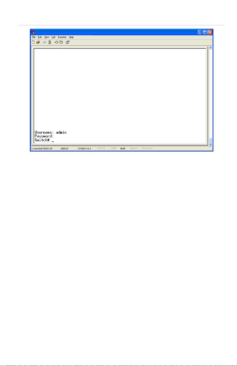
Figure 11: Lo
gin request window
Now you can configure the Switch by Telnet.
Web Browser Setup
Start Web Management
The following shows how to start up the Web Management of the GE-DSH73, GE-DSH-82 and the GE-DSH-82-PoE Managed Switch. Please note that
the Managed Switch is configured through an Ethernet connection. Make
sure the manager PC is set on the same IP subnet address.
For example, the default IP address of the GE-DS-82 Managed Switch is
192.168.0.100, then the manager PC should be set at 192.168.0.x (where x
is a number between 1 and 254, except 100), and the default subnet mask is
255.255.255.0.
P/N 1069666-EN • REV 1.01 • ISS 14JUL10 11 of 13
Page 12
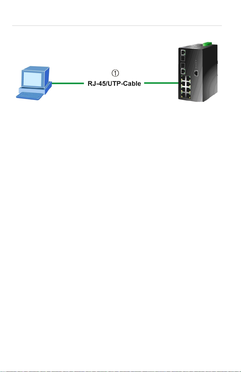
Figure 12:
PC/Workstation with IE Browser Managed Industrial Switch
IP management diagram
IP Address: 192.168.0.x IP Address: 192.168.0.100
1. RJ645 /UTP Cable
Login to the Managed Switch
1. Use Internet Explorer 6.0 or above Web browser. Enter the IP address
http://192.168.0.100 (the factory-default IP address or that you have just
changed in the console) to access the Web interface.
2. When the following dialog box appears, please enter the default
password "admin" (or the password you have changed via console). The
login screen in Figure 13 appears.
• Default IP Address: 192.168.0.100
• Default Username: admin
• Default Password: admin
12 of 13 P/N 1069666-EN • REV 1.01 • ISS 14JUL10
Page 13
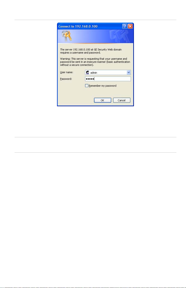
Figure 13: Lo
gin screen
3. After entering the username and password, the main screen appears.
4. Now you can use the Web management interface to continue the Switch
management. Please refer to the user manual for more information.
Note: For security reasons, please change and memorize the new password
after this first setup.
Contact information
Thank you for purchasing an IFS product. You can browse our online FAQ
resource at the Interlogix website first to check if it could solve your issue. If
you need more support information, please contact our Interlogix support
team.
888.437.3287 Toll-free in the US, Puerto Rico, and Canada.
503.885.5700 outside of the toll-free area.
For contact information, see our Web site: www.interlogix.com.
Copyright © 2011 UTC Fire & Security.
Contents subject to change without prior notice.
Interlogix is a registered trademark of UTC Fire & Security. All other trademarks belong to their
respective owners.
P/N 1069666-EN • REV 1.01 • ISS 14JUL10 13 of 13
 Loading...