

Interlogix FP 2000 Series, FP 1200 Series, FR 1100 Series, FR 1200Series Installation And Commissioning Manual
Page 1

FP/FR1100/1200/
2000 Series
Analogue addressable fire panels,
repeaters and emulators
Installation and
Commissioning Manual
Revision 6.2: February 2003
Page 2

www.aritech.com
ARCNET is a registered trademark of Datapoint Corporation.
Aritech is an Interlogix company.
COPYRIGHT
© 2001 Interlogix B.V.. All rights reserved. Interlogix B.V. grants the right to reprint this manual for internal use only. Interlogix B.V.
reserves the right to change information without notice.
Page 3

CONTENTS
NTRODUCTION
1 I
ENERAL INFORMATION
2 G
2.1 Product codes ..................................................................................................................................... 5
2.2 Design specifications........................................................................................................................... 7
ECHNICAL SPECIFICATIONS
3 T
3.1 General specifications......................................................................................................................... 9
3.2 Panel specifications........................................................................................................................... 11
3.2.1 Standard Outputs ................................................................................................................. 11
3.2.2 Standard Inputs .................................................................................................................... 12
3.2.3 Power Supply Characteristics............................................................................................... 12
3.2.4 Panel Operation.................................................................................................................... 14
3.2.5 Environmental....................................................................................................................... 15
OUNTING INSTRUCTIONS
4 M
4.1 FP/FR12xx ........................................................................................................................................ 15
4.1.1 Panel dimensions ................................................................................................................. 15
4.1.2 Mounting instructions............................................................................................................ 16
4.1.3 Panel & repeater layout ........................................................................................................ 17
4.2 FP2xxx .............................................................................................................................................. 18
4.2.1 Panel dimensions ................................................................................................................. 18
4.2.2 Mounting instructions............................................................................................................ 19
4.2.3 Panel layout.......................................................................................................................... 21
4.2.4 Repeater layout .................................................................................................................... 22
OOP DESIGN
5 L
5.1 Typical configuration ......................................................................................................................... 23
5.2 Suitable cable types .......................................................................................................................... 25
IELD CONNECTIONS
6 F
6.1 Loop, output and input connections .................................................................................................. 26
6.1.1 FP12xx ................................................................................................................................. 26
6.1.2 FP2xxx.................................................................................................................................. 27
6.2 Connections ...................................................................................................................................... 28
6.2.1 Loop connections ................................................................................................................. 28
6.2.2 Programmable relay ............................................................................................................. 30
6.2.3 Supervised outputs A ........................................................................................................... 31
6.2.4 Relay outputs B .................................................................................................................... 31
6.2.5 Supervised inputs IN5 - IN8.................................................................................................. 33
6.2.6 Auxiliary inputs (FEP2000 only)............................................................................................ 34
6.2.7 Connection of dual tone siren AS263/AS264....................................................................... 35
6.3 Communication port connections (all models) .................................................................................. 36
6.3.1 Current loop.......................................................................................................................... 36
6.3.2 RS232 ports.......................................................................................................................... 37
6.4 Power supply connections................................................................................................................. 38
6.4.1 24 V version FR2xxx models................................................................................................ 38
6.4.2 230 V version (FP/FR1xxx/FR2000 models – except FP1216EN & FP1264) ..................... 39
6.4.3 FP1216EN & FP1264 Power supply connections ................................................................ 42
6.4.4 230 V version (FP2xxx models) ........................................................................................... 43
6.5 Installing a modem ............................................................................................................................ 45
6.6 Network connections......................................................................................................................... 47
6.6.1 NC2011/NC2051 ARCNET network cards........................................................................... 47
6.6.2 NE2011/NE2051 ARCNET network extension cards........................................................... 48
6.6.3 FP/FBP/FRL700 Serial communication network (LON2000) ............................................... 49
6.7 LCD contrast ..................................................................................................................................... 50
6.7.1 FP/FR2xxx............................................................................................................................ 50
............................................................................................................................................ 4
............................................................................................................................... 5
........................................................................................................................ 9
......................................................................................................................... 15
(FP12XX/FP2
XXX
/FB2X00
ONLY
) ........................................................................................ 23
................................................................................................................................. 26
FP/FR1100/1200/2000 V6: Installation and Commissioning Manual 1
Page 4

6.7.2 FP/FR1xxx............................................................................................................................ 50
OUNTRY DEPENDENT SELECTIONS
7 C
............................................................................................................ 51
7.1 Language selections ......................................................................................................................... 51
7.1.1 FP/FR1xxx............................................................................................................................ 51
7.1.2 FP/FR2xxx............................................................................................................................ 51
7.2 Operation mode................................................................................................................................. 51
7.3 Language inserts............................................................................................................................... 51
OMMISSIONING A
8 C
FP2000 S
ERIES FIRE PANEL
.......................................................................................... 52
8.1 Before switching on........................................................................................................................... 52
8.2 Procedure for switching on................................................................................................................ 53
PPENDIX
A
SWITCH SETTINGS ON HOST
A: DIP
PSU
BOARD
(FP/FR2
XXX
)........................................................... 55
PPENDIX
A
PPENDIX
A
OFTWARE SELECTABLE OPTIONS
B: S
PERATION MODES
C: O
...................................................................................................................... 57
(FP/FR1
XXX
) ........................................................................... 56
2 FP/FR1100/1200/2000 V6: Installation and Commissioning Manual
Page 5

LIST OF FIGURES
Figure 1: Panel dimensions ........................................................................................................................ 15
Figure 2: Top/bottom cable entries............................................................................................................. 16
Figure 3: Panel layout................................................................................................................................. 17
Figure 4: Panel dimensions (cabinet size A) .............................................................................................. 18
Figure 5: Mounting instructions................................................................................................................... 19
Figure 6: Cable entries................................................................................................................................ 20
Figure 7: Panel layout................................................................................................................................. 21
Figure 8: Repeater layout ........................................................................................................................... 22
Figure 9: Class "A" return loop.................................................................................................................... 23
Figure 10: Class "A" return loop with tee offs .............................................................................................. 23
Figure 11: Class "B" Single direction loop (Star configuration)..................................................................... 24
Figure 12: Class B single direction loop with tee offs ................................................................................... 24
Figure 13: Position of inputs, loops and relay connections........................................................................... 26
Figure 14: Position of inputs, loops and relay connections........................................................................... 27
Figure 15: Class A loop connection.............................................................................................................. 28
Figure 16: Location of Class A - Class B jumpers ........................................................................................ 28
Figure 17: Class B loop connection.............................................................................................................. 29
Figure 18: Class AB loop connection............................................................................................................ 29
Figure 19: Programmable relay connections................................................................................................ 30
Figure 20: Supervised relay output’s connection on SD2000 common I/O board ........................................ 31
Figure 21: Two configurations for relay outputs 1-3 B.................................................................................. 31
Figure 22: Two configurations for relay output 4 B....................................................................................... 32
Figure 23: Location of jumpers on sounder board........................................................................................ 32
Figure 24: Supervised inputs connections.................................................................................................... 33
Figure 25: Auxiliary inputs............................................................................................................................. 34
Figure 26: Dual tone siren connections ........................................................................................................ 35
Figure 27: Current loop terminal connections............................................................................................... 36
Figure 28: FP/FR2xxx power supply connections (24 V version)................................................................. 38
Figure 29: FP/FR12xx/FR2000 connecting mains-to-mains terminal block ................................................. 39
Figure 30: FP/FR12xx power supply and fault relay connections................................................................. 40
Figure 31: FP/FR12xx power supply’s fault relay connections ..................................................................... 41
Figure 32: FP1216EN & FP1264 power supply and transformer connections ............................................. 42
Figure 33: FP2xxx power supply and associated connections (230 V version)............................................ 43
Figure 34: Modem MOD2000 interconnection diagram................................................................................ 46
Figure 35: Network interface and associated connection............................................................................. 47
Figure 36: NE2011 network extension module............................................................................................. 48
Figure 37: Mounting position of LON2000 board.......................................................................................... 49
Figure 38: FP1xxx/2xxx Lon port terminal connections................................................................................ 49
Figure 39: Adjustment of the LCD viewing angle.......................................................................................... 50
FP/FR1100/1200/2000 V6: Installation and Commissioning Manual 3
Page 6

1 I
NTRODUCTION
The purpose of this manual is to provide assistance during the installation and
commissioning of the FP/FR1100/1200/2000 Series fire panels, and repeaters/emulators.
Please note that the manual is intended as a guide only and is not to be used to replace
any local building and/or wiring codes.
Other manuals available are:
1. Aritech 900 Series Detectors Installation Manual
2. Aritech 2000 Series Detectors Installation Manual
3. FP1200/2000 Reference Guide
4. FP2000 Series Network Configuration Guide
5. FP1200/2000 End User Manual
Warning
This is a class A product. In a domestic environment this product may cause radio
interference in which case the user may be required to take adequate measures.
4 FP/FR1100/1200/2000 V6: Installation and Commissioning Manual
Page 7
2 GENERAL INFORMATION
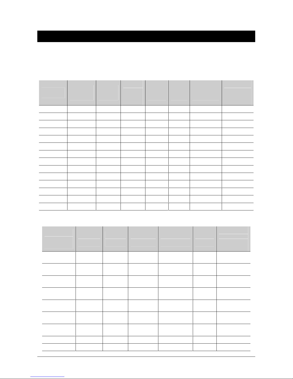
2.1 Product codes
FIRE PANELS:
Max. nr.
Firepanel
FP1200-00 0 4A/4B 126/128 Apollo No 365x444x112 8
FP1200-01 0 2A/2B 64/128 Sentrol No 365x444x112 8
FP1200-02 0 2A/2B 64 Sentrol No 365x444x112 8
FP1216 1xZE2016 2A/4B 126/128 Sentrol No 365x444x112 8
FP1216EN 1x ZE2016 2A/4B 126/128 Sentrol No 440x444x112 9
FP1264 1xZE2064 2A/4B 126/128 Sentrol No 440x444x125 9
FP2416 1xZE2016 2A/4B 126/128 Sentrol Yes 609x441x109 11
FP2464 1xZE2064 2A/4B 126/128 Sentrol Yes 609x441x109 11
FP2432 2xZE2016 4A/8B 126/128 Sentrol No 609x441x109 11
FP24128 2xZE2064 4A/8B 126/128 Sentrol No 609x441x109 11
FP2864 4xZE2016 8A/16B 126/128 Sentrol Yes 804x441x109 15
FP28255 4xZE2064 8A/16B 126/128 Sentrol Yes 804x441x109 15
FB2400 0 4A/8B 126/128 Sentrol No 609x441x109 11
FB2800 0 8A/16B 126/128 Sentrol No 804x441x109 15
Max. nr. of
zone cards
Max. nr.
of loops
of
detectors
/ loop
Default
detector
Internal
printer
Cabinet Size
(mm)
Approx.
weight (kg)
(without
batteries)
REPEATERS / EMULATORS:
Repeater/
Emulator
Panel
FR1200 0 No 365x444x
FR2000 0 No 365x444x
FR2032 2xZE2016 No 609x441x
FR20128 2xZE2064 No 609x441x
FR2064 4xZE2016 Yes 804x441x
FR20255 4xZE2064 Yes 804x441x
FM808/816/
832/864
FR808 N/A No 320x315x90 Current Loop 230 VDC 2
FR824 N/A No 516x346x80 Current Loop 230 VDC 8
Max. nr. of
zone cards
0 No Mimic only Current Loop 24 VDC No cabinet
Internal
printer
Cabinet Size
(mm)
112
112
109
109
109
109
Connected to
FP1200/ 2000
NC2011/
NC2051
NC2011/
NC2051
NC2011/
NC2051
NC2011/
NC2051
NC2011/
NC2051
NC2011/
NC2051
Voltage
Source
230 VAC 8
230 VAC 8
24 VDC 11
24 VDC 11
24 VDC 15
24 VDC 15
Approx.
weight (kg)
(without
batteries)
FP/FR1100/1200/2000 V6: Installation and Commissioning Manual 5
Page 8
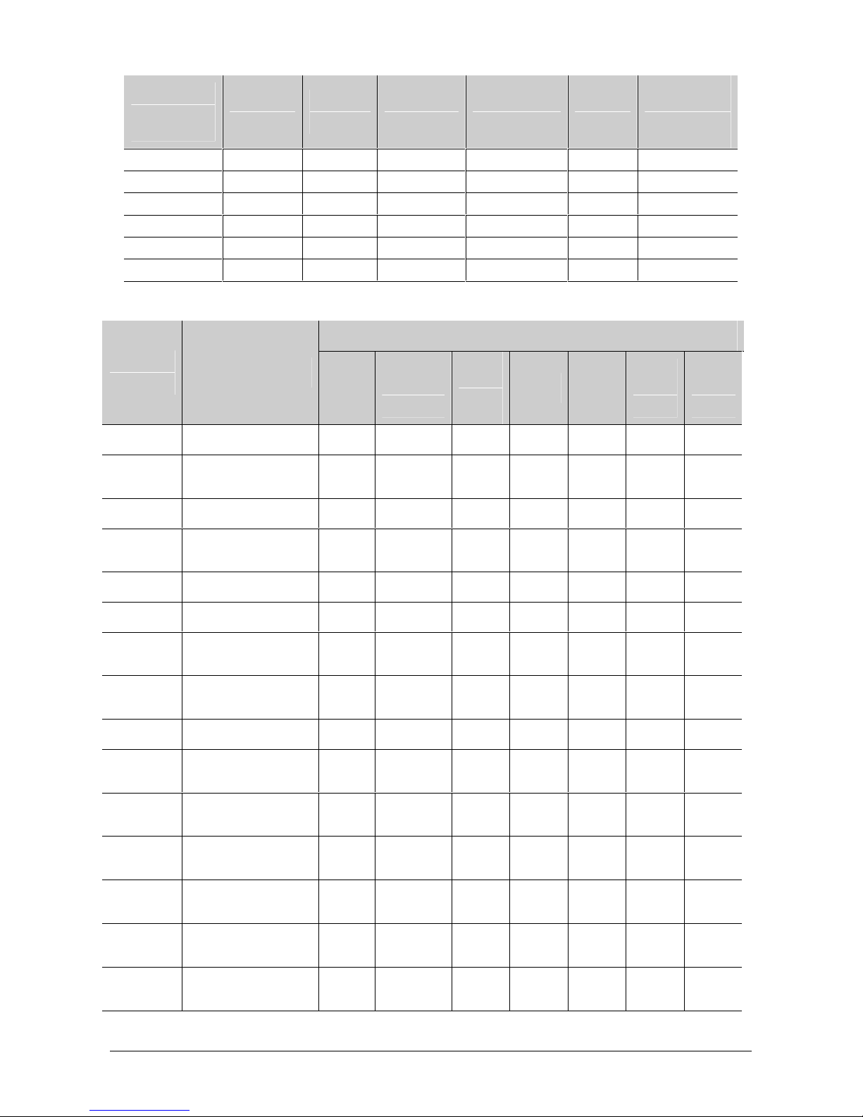
Repeater/
Emulator
Panel
FR832 N/A No 516x346x80 Current Loop 230V DC 8
FBP700-D 0 No 240x320x60 LON2000 24 VDC 1.5
FBP700-S 0 No 240x320x60 LON2000 24 VDC 1.5
FRL700 0 No 240x320x60 LON2000 24 VDC 1.5
RP2032 0 No 397x290x64 Current Loop 24 VDC 3
UN2000 0 No 290x145x80 NC/NE2011 230 VAC 1.5
Max. nr. of
zone cards
Internal
printer
Cabinet Size
(mm)
Connected to
FP1200/ 2000
Voltage
Source
Approx.
weight (kg)
(without
batteries)
OPTIONS:
Compatibility with
Extra
Modules
LC2002 Loop driver extension • • • •
LON2000 LON protocol
Description
converter
FP1216EN/
FP1216
2416/2432/
2864
• • • • • • •
FP1264
/ 2464/
24128/
28255
FB2x00 FR1200
FR2000
/ 2032/
2064
FR2012
20255
8/
MOD2000 Modem • • • • • •
NA2004 4-way network
NC2011 Network card - RS485 • • • • • • •
NC2051 Network card - optical • • • • • • •
NE2011 Network extension
NE2051 Network extension
PE2485 French CMSI interface •* •* • • •
PR2000/
PR2011
RB2016 16 programmable
SD1200 3 output sounder
SD2000 4 input/8 output
amplifier
card - RS485
card – optical
Internal printer (40
column impact printer)
relay board
board
sounder board
• • • • • •
• • • • • • •
• • • • • • •
•** •** •* •*
• • • •
•
• • •
VdS2000 German sounder
ZE2016 16 zones LED
board
extension
6 FP/FR1100/1200/2000 V6: Installation and Commissioning Manual
•
• • •
Page 9
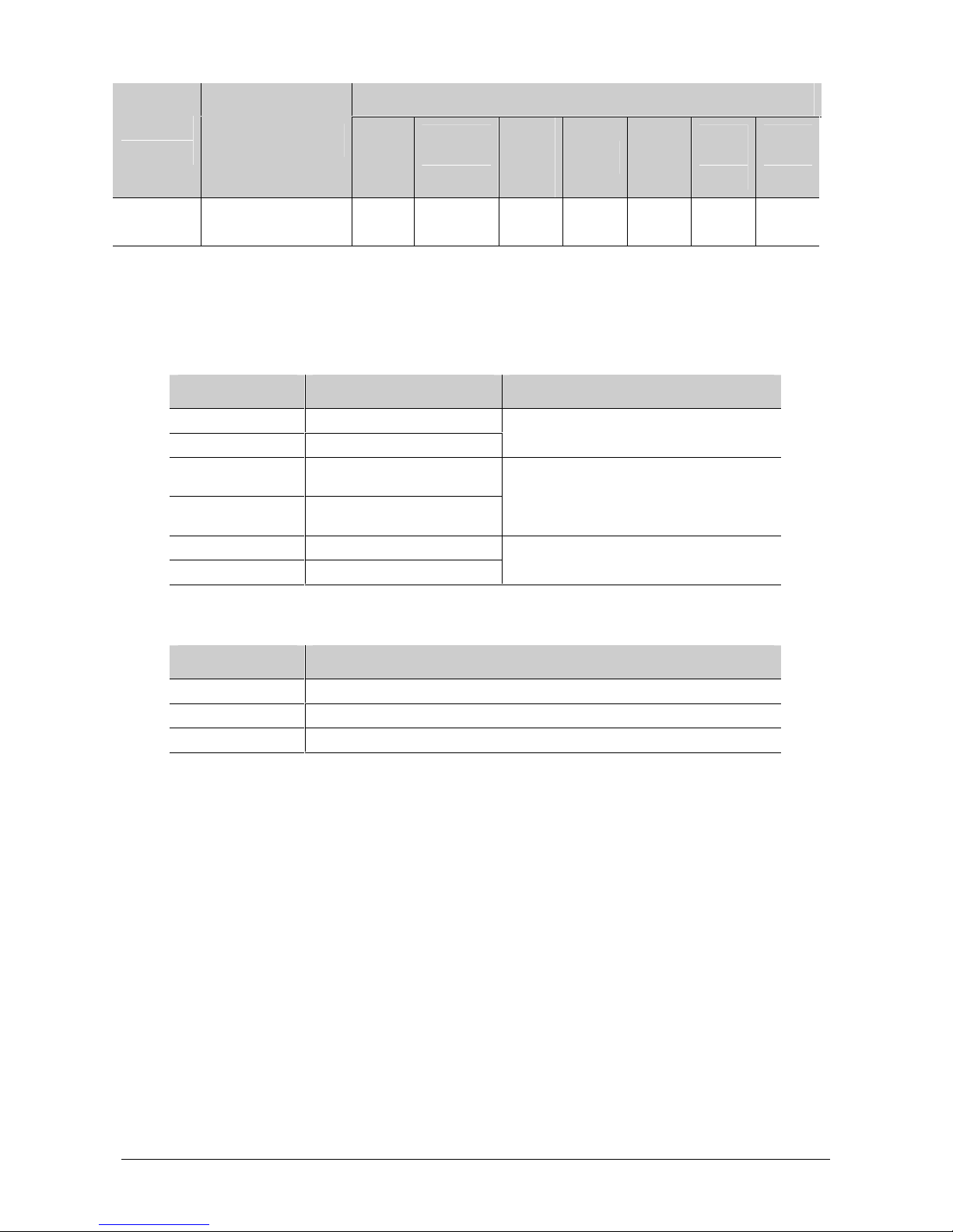
Compatibility with
Extra
Modules
ZE2064 64 zones LED
Description
extension
* Excludes the FP1200 series of firepanels
** Option on FP2416/2464, FP2864/28255 & FR20255 only
MODULE VARIATION:
Board Product used in Variation
FEP1200 FP11xx/12xx FEP1200 – 0 x Auxiliary inputs
FEP2000 FP2xxx/FB2x00 FEP2000 – 4 x Auxiliary inputs
FC1200 FP11xx/12xx & FR12xx FC1200 – 1 x DB9 port, Real Time Clock
FC2011 FP2xxx/FB2x00 & FR20xx FC2011 – 2 x DB9 ports, Real Time Clock
LCD1200 FP11xx/12xx & FR12xx LCD1200 – No LCD backlight
LCD2000/2011 FP/FR2xxx LCD2011 – LCD backlight
FP1216EN/
FP1216
2416/2432/
2864
• •
FP1264
/ 2464/
24128/
28255
without battery backup
with battery backup
FB2x00 FR1200
FR2000
/ 2032/
2064
FR2012
8/
20255
SOFTWARE:
Software Package Description
PCM2000 Maintenance Manager
PCC2000 FPConfig – Configuration Software (up/download)
PCG2000 Graphical User Interface
2.2 Design specifications
The FP1100/1200/2000 series fire panels are designed to comply with the requirements
of EN54-2 (control and indicating equipment) and EN54-4 (power supply equipment).
The panels have the following options with requirements according to EN54-2:
•
Output to fire alarm devices
•
Output to fire alarm routing equipment (according to DIN VDE0833)
• Output to fire protection equipment (according to VdS-directive)
• Delays to outputs
• Coincidence detection
• Alarm counter
FP/FR1100/1200/2000 V6: Installation and Commissioning Manual 7
Page 10

• Fault/disablements from addressable points
• Output to fault warning routing equipment
•
Standardised input/output interface (according to DIN 14661)
•
Test condition
•
Total loss of power supply (option)
8 FP/FR1100/1200/2000 V6: Installation and Commissioning Manual
Page 11

3 TECHNICAL SPECIFICATIONS
3.1 General specifications
Loop capacity:
• Every loop PCB (LC2002) can be configured as two class A loops or four class B
loops. (Except FP1200-00 2A/4B or 4A/4B; FP1200-01 2A/2B; FP1200-02 2A/2B)
• Addressable devices per loop: 126 (900 Series) or 128 (2000 Series)
• Maximum 1008 (900 Series) or 1024 (2000 Series) addressable devices per panel
• Maximum eight loops per panel (FP2000 range only)
• Loop overload: >500 mA
•
Loop operating load: 100 mA maximum
Zone capacity:
•
16 or 64 zones (expandable to 32/128, 48/192 or 64/255 zones in cabinet size B)
•
112 zones for control purposes
LCD screen:
•
Backlit alphanumeric 8 x 40 character LCD
Indicators:
• General indicators
Fire - 2 x LED - Red
Fault - 1 x LED - Amber
Disable - 1 x LED - Amber
Supply fault - 1 x LED - Amber
System fault - 1 x LED - Amber
Processor running - 1 x LED - Green
Supply On - 1 x LED - Green
• Control indicators
Silence buzzer - 1 x LED - Amber
Disable - 1 x LED - Amber
Test - 1 x LED - Amber
Third source test - 1 x LED - Amber
• Sounders indicators
Sound - 1 x LED - Red
Delay On - 1 x LED - Amber
Delay Off - 1 x LED - Amber
Fault/Disable - 1 x LED - Amber
Silence - 1 x LED - Amber
FP/FR1100/1200/2000 V6: Installation and Commissioning Manual 9
Page 12

• Fire brigade indicators
Signal - 1 x LED - Red
Delay On - 1 x LED - Amber
Delay Off - 1 x LED - Amber
Fault/Disable - 1 x LED - Amber
Stop fire brigade - 1 x LED - Amber
• Zone monitoring indicators
Fire - 16/64 x LED - Red (expandable to 32/128, 48/192 or
64/255)
Fault - 16/64 x LED - Amber (expandable to 32/128, 48/192
or 64/255)
•
Indicators related to network facilities
All - 1 x LED - Amber
Panel - 1 x LED - Amber
Membrane keyboard:
1, 2, 3, 4, 5, 6, 7, 8, 9, 0, A .. Z
General control keys:
Silence buzzer
Reset
Disable
Test
Third source test
Sounders control:
Sound
Delay On/Delay Off
Disable
Silence
Fire brigade control:
Signal
Delay On/Delay Off
Disable
Stop fire brigade
Control keys related to network facilities (Excludes FP12xx range):
All
Panel
Control key switch:
Prevents unauthorised resetting and programming of the fire panel.
10 FP/FR1100/1200/2000 V6: Installation and Commissioning Manual
Page 13
Tamper switch (FP2000 Range only):
Fitted to the inside of the fire panel door to record any entry to the cabinet.
Third source (when implemented on the FP2000 range only):
Test button and LED to test total loss of power supply.
Communication ports:
•
2 x DB-9 serial port (set-up, upload/download, internal printer (where applicable),
graphics, remote operation/graphic package)
• 1 x current loop (to connect repeaters and fireman’s panels)
Current Loop:
• Maximum 15 devices
•
Maximum 1 km between 2 current loop devices
•
Aritech FM800 / FR800 - German fire brigade panel (according to DIN 14661) can be
connected.
•
Cable capacitance max. 150 nF
3.2 Panel specifications
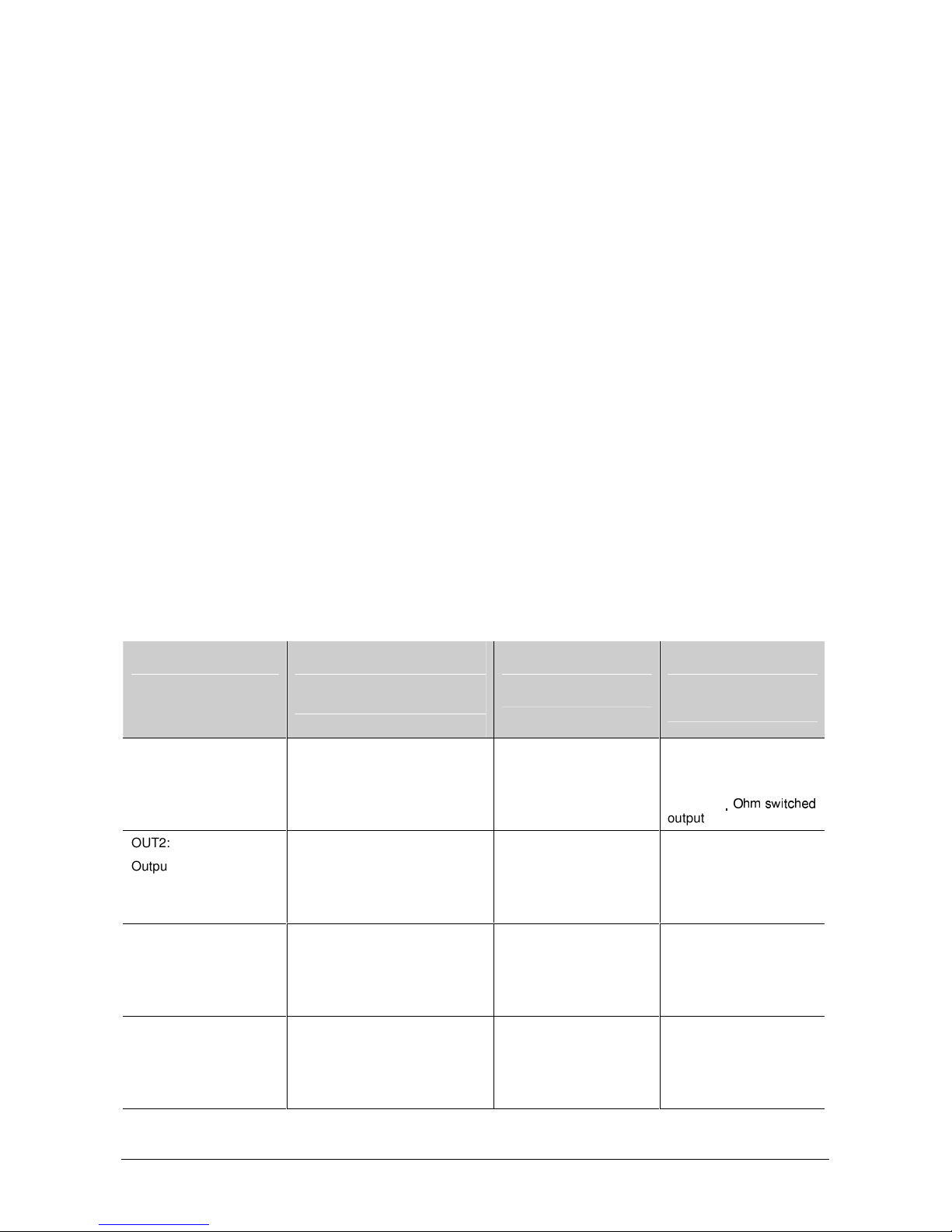
3.2.1 Standard Outputs
Standard Outputs
(All standard outputs are
located on the sounder
board.)
OUT 1:
Output to alarm devices
(Sounders)
OUT2:
Output to fire routing
equipment (Fire brigade)
OUT3:
Output to fire protection
equipment
OUT4:
Output to fault warning
routings equipment
FP/FR1xxx & FR2000
(
FP1100 and FP1216 only;
FP1200 optional – SD1200
board used)
A: 24 V – 100 mA supervised*
(Supervision at 5V max.)
B: 3K3/680 Ohm switched
output
A: 24 V – 100 mA supervised*
(Supervision at 5 V max.)
B: 3K3/680 Ohm switched
output
A: 24 V – 100 mA supervised*
(Supervision at 5 V max.)
B: 3K3/680 Ohm switched
output
A: 24 V – 100 mA supervised*
(Supervision at 5 V max.)
B: 3K3/680 Ohm switched
output
FP1216EN & FP1264
(SD2000 board)
A: 24 V - 0.8 A
supervised (Supervision
at 5 V max.)
B: 3K3/680 Ohm
switched output
A: 24 V - 0.8 A
supervised (Supervision
at 5 V max.)
B: 3K3/680 Ohm
switched output
A: 24 V - 0.1 A
supervised (Supervision
at 5 V max.)
B: 3K3/680 Ohm
switched output
A: 24 V - 0.1 A
supervised (Supervision
at 5 V max.)
B: 3K3/680 Ohm
switched output
FP/FR2xxx
(FP2xxx only -
SD2000 board used)
A: 24 V - 0.8 A
supervised (Supervision
at 5 V max.)
B: 3K3/680
output
A: 24 V - 0.8 A
supervised (Supervision
at 5V max.)
B: 3K3/680 Ohm
switched output
A: 24 V - 0.1 A
supervised (Supervision
at 5 V max.)
B: 3K3/680 Ohm
switched output
A: 24 V - 0.1 A
supervised (Supervision
at 5 V max.)
B: 3K3/680 Ohm
switched output
FP/FR1100/1200/2000 V6: Installation and Commissioning Manual 11
Page 14

Standard Outputs
(All standard outputs are
located on the sounder
board.)
OUT5 – OUT8:
4 programmable relays
(Three terminals each:
COM - NO – NC)
FP/FR1xxx & FR2000
(
FP1100 and FP1216 only;
FP1200 optional – SD1200
board used)
Maximum switching current: 2 A
@ 24 VDC
Maximum power rating:
50 W DC
250 VA
FP1216EN & FP1264
(SD2000 board)
Maximum switching
current:
2 A @ 24 V DC
Maximum power rating:
50 W DC
250 VA
FP/FR2xxx
(FP2xxx only -
SD2000 board used)
Maximum switching
current:
2 A @ 24 VDC
Maximum power rating:
50 W DC
250 VA
* The maximum specified current of 100 mA for Output 1 and Output 2 can be exceeded as long as the total
current drawn by the outputs (1-4) is limited to 400 mA.
3.2.2 Standard Inputs
Standard Inputs
Sounder card 4 x supervised inputs
FEP board (FP2xxx and
FB2x00 only)
FP/FR1xxx & FR2000
(FP1100 and FP1216
only; FP1200 optional –
SD1200 board used)
(inputs 1-4)
3.3 kOhm termination
4 x auxiliary inputs
FP1216EN & FP1264
(SD2000 board)
4 x supervised inputs
(inputs 1-4)
3.3 kOhm termination
FP/FR2xxx
(FP2xxx only – SD2000
board used)
4 x supervised inputs
(inputs 1-4)
3.3 kOhm termination
15 VAC or 20-28 VDC
3 mA
3.2.3 Power Supply Characteristics
Power Supply
Characteristics
Input 230 VAC (+10%, -
Output Aux. Power:
Supervisory - Mains fail
FP/FR1xxx &
FR2000
15%)
50 Hz (±10%)
50 VA
21 – 28 VDC
24 V standby battery
19-27.5 VDC, 100
mA (max)
Modem: 5 VDC
(±0.1V), 75mA (max)
Battery charge: 27.6
VDC (±0.2 V) @ 25
°C, 300 mA (max)
- Battery disconnect
FP1216EN &
FP1264
230 VAC (+10%, 15%)
50 Hz (±10%)
220 VA
21 – 28 VDC
24 V standby battery
Aux. Power: 19-27.5
VDC, 100 mA (max)
Modem: 5 VDC
(±0.1V), 75 mA
(max)
Battery charge:
27.6 VDC (±0.2 V) @
25 °C, 1.6 A (max)
- Mains fail
- Battery disconnect
FP/FR2xxx
230 VAC (±15%)
50 Hz (±10%)
200 VA
21 – 28 VDC
24 V standby battery
Auxiliary Voltage:
20.5-28 V
27.6V DC battery
charge voltage, 4A
total (battery charge
and aux. with or
without batteries.)
- Mains fail
- Battery disconnect
FR2032/20128
FR2064/20255
21 – 28 VDC
24 V standby battery
- Mains fail
- Charger fail
12 FP/FR1100/1200/2000 V6: Installation and Commissioning Manual
Page 15

Power Supply
Characteristics
Fuses AC fuse – 0.8 A,
Maximum current
drawn from the
primary input
Maximum output
ripple voltage
Fault Relay
(Configuration
depended on jumper
setting – refer to
section 6.4.2.2.)
FP/FR1xxx &
FR2000
- Battery flat
- Flat battery cut-out
- Earth fault
- Auxiliary supply
fault
250 V, T
(20 mm STD fuse)
250 mA 1 A 1 A 0.3 A (no options
± 300 mV ± 300 mV ± 300 mV
Maximum switching
current:
2A @ 24 VDC
Maximum power
rating:
50 W
FP1216EN &
FP1264
- Battery flat
- Flat battery cut-out
- Earth fault
- Auxiliary supply
fault
AC fuse – 2 A,
250 V, T
(20mm STD fuse)
Maximum switching
current:
2 A @ 24VDC
Maximum power
rating:
50 W
FP/FR2xxx
- Battery flat
- Flat battery cut-out
AC fuse – 2 A
(20 mm STD fuse)
Aux. Output – 5 A
(20 mm STD fuse)
Battery fuse – 5 A
(20 mm STD fuse)
- -
FR2032/20128
FR2064/20255
Fuse – 1 A
(20 mm STD fuse)
installed)
FP/FR1100/1200/2000 V6: Installation and Commissioning Manual 13
Page 16

3.2.4 Panel Operation
Battery operation - Normal operation
(No mains power)
Current required by system 200 mA (max) 200 mA (max) 200 mA (max)
Loop current
- 2 loops
- 127 devices/loop @ 340 µA/device (DP951)
Auxiliary current 0 mA 0 mA 0 mA
Total normal current 286 mA 200 mA 286 mA
FP12XX FR1200/FR2000 FP1216EN & FP1264
86 mA
0 mA
86 mA
Battery Operation - Alarm Operation
(No mains power)
Normal current (as above) 286 mA (max) 200 mA (max) 286 mA (max)
Extra loop current (20 x LED @ 4 mA) 80 mA 0 mA 80 mA
Sounders (Sounder board: Outputs 1-4) 200 mA 0 mA 200 mA
Total alarm current 566 mA 200 mA 566 mA
FP12XX FR1200/FR2000 FP1216EN & FP1264
Normal Operation FP2416/2464 & FP2432/24128 FP2864, FP28255
Mains load (maximum) 200 VA 200 VA
Total output current (27.6 V) 4 A 4 A
Battery capacity I
Battery capacity (maximum) 69 AH 69 AH
Required battery charging current
(Maximum battery capacity)
Current required by system (I
Available auxiliary current 0.45 A 0.15 A
= 0 (72H standby) 36 AH 58 AH
AUX
3.05 A 3.05 A
)* 0.5 A 0.8 A
SYS
Alarm Operation FP2416/2464 & FP2432/24128 FP2864, FP28255
Mains load (maximum) 200 VA 200 VA
Total output current (27.6 V) 4 A 4 A
Required battery charging current
(Maximum battery capacity)
Current required by system 0.6 A 1 A
Available auxiliary current 3.4 A 3 A
0 A 0 A
*I
calculated at 252 x 900 series ionisation detectors (FP2416/64) 1008 x 900 series ionisation detectors
SYS
(FP2864/255)
Charging current based to charge batteries up to 80% in 24 hours at 75% efficiency
14 FP/FR1100/1200/2000 V6: Installation and Commissioning Manual
Page 17
3.2.5 Environmental
Environmental FP/FR1xxx & FR2000
Enclosure protection IP54 IP54 IP54
Temperature
Operational: -5 ºC to +40 ºC
Storage: -20 ºC to +60 ºC
FP1216EN & FP1264
Operational: - 5 ºC to +40 ºC
Storage: -20 ºC to +60 ºC
Operational: - 5 ºC to +40 ºC
Storage: -20 ºC to +60 ºC
4 MOUNTING INSTRUCTIONS
4.1 FP/FR12xx
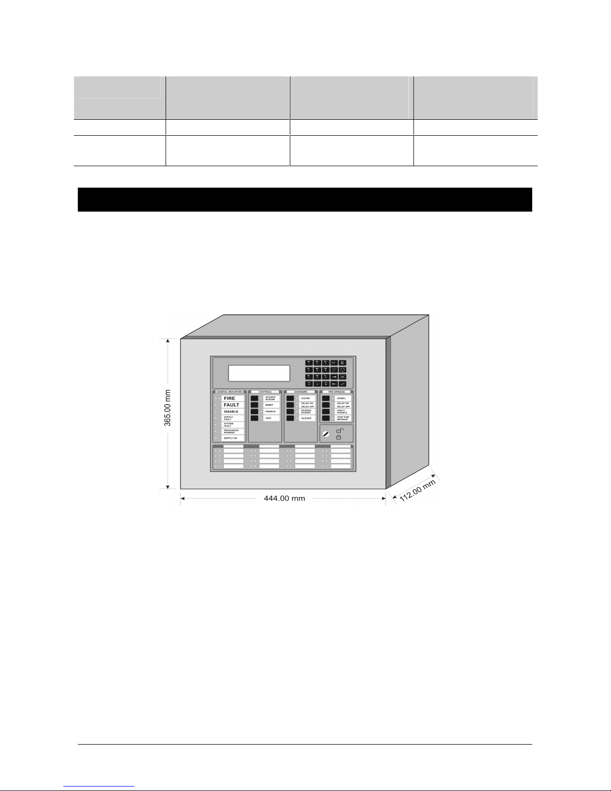
4.1.1 Panel dimensions
Figure 1: Panel dimensions
FP/FR2xxx
"
All dimensions are in mm.
FP1200/FP1216/FR1200/FR2000: 365 X 444 X 112 (H X W X D) mm
FP1216EN/FP1264: 440 X 444 X 125 (H X W X D) mm
FP/FR1100/1200/2000 V6: Installation and Commissioning Manual 15
Page 18
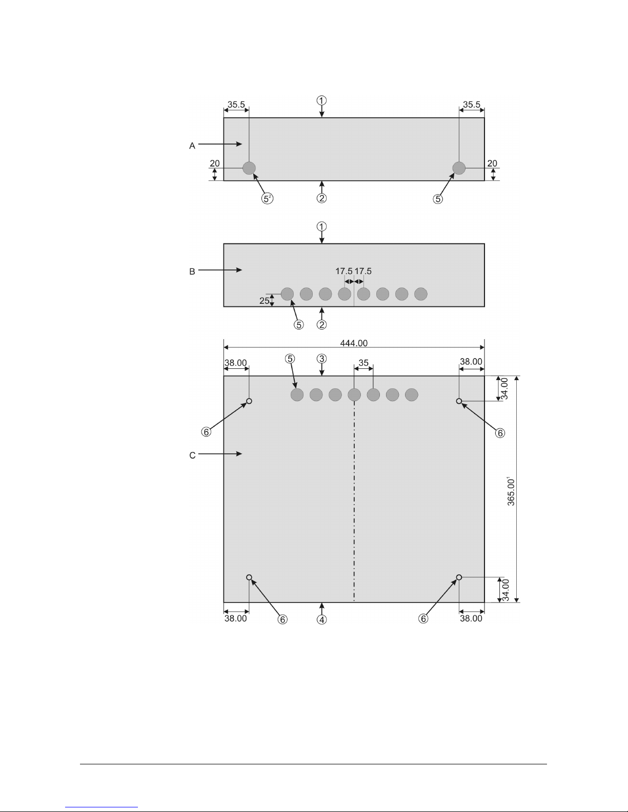
4.1.2 Mounting instructions
Figure 2: Top/bottom cable entries
1. Panel front A. Bottom view
2. Rear mounting surface B. Top view
3. Panel top C. Rear panel view
4. Panel bottom
5. Cable entries 20 mm
6. Mounting holes 5 mm
16 FP/FR1100/1200/2000 V6: Installation and Commissioning Manual
1
440 mm for the FP1216EN & FP1264
2
Not applicable to FP1216EN & FP1264
Page 19

CAUTION! Mains wires (230 V) must enter the cabinet from the right bottom hole in the
problems.
cabinet only.
Top entry violates IEC950 safety requirements and will cause EMC
Mains wires must not be routed past the electronic modules in the rear of the panel. It
must be kept as short as possible and routed directly to the mains input.
4.1.3 Panel & repeater layout
Figure 3: Panel layout
A. FP1216EN & FP1264 16. Host CPU board
B. FR1200 & FR2000 17. DB-9 port
1. Transformer 18. RS232 and current loop routing of wires
2. Battery link 19. ARCNET network card (top) (optional)
3. Battery terminal (+) (red) 20. Battery terminal (-) (black)
4. Mains terminal block 21. Battery and power supply connection terminals
5. Earth stud 22. Modem (MOD2000) power supply terminals
6. Main fuse and switch 23. Front-end processor board
7. Batteries 12V (2x) (optional) 24. Power supply board
8. Zone matrix display board (bottom) (optional) 25. Fault relay connections
9. Common LED board 26. Auxiliary power connections
10. Service commission mode select 27. Loop 1-4 terminal connections
11. Non-volatile memory lock 28. 2 Loop driver board
12. Memory back-up battery jumper 29. Sounder relay board
13. Numeric keypad 30. Modem (MOD2000) (optional)
14. LCD display 31. ARCNET network card (bottom) (NC2011)
15. Current loop terminals
FP/FR1100/1200/2000 V6: Installation and Commissioning Manual 17
Page 20

4.2 FP2xxx
4.2.1 Panel dimensions
Figure 4: Panel dimensions (cabinet size A)
"
Cabinet size B: 804 x 441 x 109 mm (H x W x D)
Cabinet size C: 473.5 x 441 x 109 mm(H x W x D)
18 FP/FR1100/1200/2000 V6: Installation and Commissioning Manual
Page 21

4.2.2 Mounting instructions
Figure 5: Mounting instructions
A. Cabinet size A C. Cabinet size C
B. Cabinet size B 1. 4 x 5 mm mounting holes
The 5 mm mounting holes are located as shown in Figure 2.
Five 20 mm holes are provided for cable entry at the top and bottom of the panel.
FP/FR1100/1200/2000 V6: Installation and Commissioning Manual 19
Page 22

The total panel weight equals: 11 kg for size A cabinet (excluding batteries)
15 kg for size B cabinet (excluding batteries)
9 kg for size C cabinet (excluding batteries)
Figure 6: Cable entries
CAUTION! Mains wires (230V) must enter the cabinet from the left bottom hole in the
cabinet only. Top entry violates EN60950 (IEC950) safety requirements and will
cause EMC
Mains wires must not be routed past the electronic modules in the rear of the panel. It
must be kept as short as possible and routed directly to the mains input connected to the
power supply (PS2000)
problems.
20 FP/FR1100/1200/2000 V6: Installation and Commissioning Manual
Page 23

4.2.3 Panel layout
Figure 7: Panel layout
1. Numeric keypad 15. 2 x battery
2. Common LED board 16. Power supply and battery charger
3. LCD Display and backlight board 17. Modem (optional)
4. Host processor board 18. Optional ARCNET network card
5. Current loop terminal connections 19. Host power supply board
6. RS232 ports (DB-9connectors) (port 1-front; port 2-back) 20. Bus-termination card
7. DB9-DB25 adapter (with modem) 21. DIP switch
8. Front-end processor board 22. Zone matrix display board
9. FEP power supply board 23. Optional internal printer (PR2000)
10. 2 Loop driver board (x2) 24. Service/commission mode switch
11. Sounder relay board 25. Non-volatile memory lock
12. Auxiliary inputs terminal connections 26. Memory back-up battery jumper
13. Loop 1-4 terminal connections 27. Optional third source battery
14. Terminal connections sounder board
FP/FR1100/1200/2000 V6: Installation and Commissioning Manual 21
Page 24

4.2.4 Repeater layout
Figure 8: Repeater layout
1. Numeric keypad 10. Bus-termination card
2. Common LED board 11. DIP switch
3. LCD Display and backlight board 12. Zone matrix display board
4. Host processor board 13. Optional internal printer (PR2000)
5. Current loop terminal connections 14. Service/commission mode switch
6. RS232 ports (DB-9 connectors) (port 1-front; port 2back)
7. 24 VDC power supply 16. Memory back-up battery jumper
8. Optional ARCNET network card 17. Optional third source battery
9. Host power supply board
15. Non-volatile memory lock
22 FP/FR1100/1200/2000 V6: Installation and Commissioning Manual
Page 25

5 LOOP DESIGN (FP12XX/FP2XXX/FB2X00 ONLY)
5.1 Typical configuration
The fire panel accepts the following loop configurations.
Figure 9: Class "A" return loop
Figure 10: Class "A" return loop with tee offs
FP/FR1100/1200/2000 V6: Installation and Commissioning Manual 23
Page 26

Figure 11: Class "B" Single direction loop (Star configuration)
Figure 12: Class B single direction loop with tee offs
A maximum of 126 detectors (900 Series) or 128 detectors (2000 Series) can be
connected to a loop. For combinations of fire sensing devices, monitoring controllers and
input/output devices, the maximum number of addressable units must be calculated.
Please refer to the Installation Manual of the 900 Series and 2000 Series detectors.
"
EN54 specifies that a short circuit or an interruption in a detection circuit
cannot prevent the indication of a fire alarm from more than 32 fire detectors
and/or manual call points.
Therefore, when more than 32 detectors are connected to one loop, an
isolator should be placed at least at every 32 devices. In that case, a class A
configuration (no Tee Offs) should always be used.
" EN54 specifies that in case of a system fault, not more than 512 fire
detectors and/or manual call points and their associated mandatory functions
shall be affected. Taking this into consideration, the amount of detectors per
panel should be limited to 512.
24 FP/FR1100/1200/2000 V6: Installation and Commissioning Manual
Page 27

5.2 Suitable cable types
The maximum serial cable resistance must be no more than 100 ohm and the maximum
loop capacitance in parallel with this should not exceed 1uF.
This will ensure that 126 (900 Series) or 128 (2000 Series) detectors can be operated
over a distance of 2 km.
"
The cable resistance limit is calculated to maintain the minimum required
supply - voltage in the presence of the worst-case load conditions.
FP/FR1100/1200/2000 V6: Installation and Commissioning Manual 25
Page 28

6 F
IELD CONNECTIONS
6.1 Loop, output and input connections
6.1.1 FP12xx
Figure 13: Position of inputs, loops and relay connections
1. FEP 9. Fire alarm devices
2. Power supply board 10. General input (FP1216/64 only)
3. Loop driver 11. Fault routing return input FP1216/64 only)
4. Sounder board 12. Fire protection return input (FP1216/64 only)
5. Programmable relays (FP1216/64 only) 13. Fire brigade return input (FP1216/64 only)
6. Fault routing (FP1216/64 only) 14. 2 x class A loops or 2 x class B loops
7. Fire protection 15. Auxiliary power
8. Fire routing 16. Fault relay
26 FP/FR1100/1200/2000 V6: Installation and Commissioning Manual
Page 29

6.1.2 FP2xxx
Figure 14: Position of inputs, loops and relay connections
1. FEP 9. Fire alarm devices
2. Power supply board 10. General input
3. Line driver 11. Fault routing return input
4. Sounder board 12. Fire protection return input
5. Programmable relays 13. Fire brigade return input
6. Fault routing 14. 2 x class A loops or 2 x class B loops
7. Fire protection 15. 4 Auxiliary inputs
8. Fire routing
FP/FR1100/1200/2000 V6: Installation and Commissioning Manual 27
Page 30

6.2 Connections
6.2.1 Loop connections
Standard, the panel is configured in a class A set-up (see also Chapter 5, Loop design):
Figure 15: Class A loop connection
1. Forward 3. Loop 1
2. Return 4. Loop 2
When class B operation is required, the A-jumpers should be removed to double the
amount of loops. The B-jumpers should be put in. If 8 A class loops are in use and the Bjumpers are put in only the first 8 loops will be class B.
Figure 16: Location of Class A - Class B jumpers
28 FP/FR1100/1200/2000 V6: Installation and Commissioning Manual
Page 31

Figure 17: Class B loop connection
1. Forward 3. Loop 1
2. Return 4. Loop 2
" y The FWD and Return of each class A loop used must be linked in the
correct polarity
y Isolators are polarity dependant (see Detector Installation and
Commissioning Manual)
y Preferably loop boards must be configured for class A
y A and B loops can be combined in the following way:
a) Configure as class A
b) Class B loops are connected as follows:
Figure 18: Class AB loop connection
1. Forward 3. Loop 1
2. Return
y The maximum of loops (either A or B) in one panel is limited to eight.
y All loop cards in a panel must be configured in the same way (either A or
B).
Loop devices
The FP2000 Series of analogue addressable fire panels are fully compatible with the
Aritech 900 range of detectors and manual call points, as well as with the Aritech range of
monitoring controllers and input/output devices. They are also fully compatible with the
Aritech Intrinsically Safe range of fire detectors.
The FP2000 Series of fire panels are also fully compatible with the Aritech 2000 range of
detectors, manual call points and input/output devices.
Dip switch 7 on the Host Power Supply board must be in the ON (up) position when using
Aritech 900 devices and in the OFF (down) position when using the Aritech 2000 devices.
(See Appendix A).
For information on any devices, refer to the appropriate Installation and Commissioning
Manual.
FP/FR1100/1200/2000 V6: Installation and Commissioning Manual 29
Page 32

6.2.2 Programmable relay
Each of the four programmable relays has a change over contact. The relay is shown in
the NORMAL state. A red LED indicates the state of the relays.
Figure 19: Programmable relay connections
1. Programmable relay 4 (Out8) 7. Output 6 switched LED indication
2. Programmable relay 3 (Out7) 8. Output 5 switched LED indication
3. Programmable relay 2 (Out6) 9. Common
4. Programmable relay 1 (Out5) 10. Normally closed (Relay shown in
5. Output 8 switched LED indication 11. Normally open
6. Output 7 switched LED indication
NORMAL state)
30 FP/FR1100/1200/2000 V6: Installation and Commissioning Manual
Page 33

6.2.3 Supervised outputs A
These outputs provide 24 VDC when active. A red LED displays the state of the outputs.
(Refer to sections 3.2.1 and 3.2.3 for technical information on these outputs.)
Figure 20: Supervised relay output’s connection on SD2000 common I/O board
1. Fault routing (Out4)
* Termination resistor - 3k3
* Including relay coil resistance
* Polarity non-reversed
* Active in normal position
2. Fire protection device (Out3)
* Termination resistor - 3k3
* Including relay coil resistance
* Polarity non-reversed
6.2.4 Relay outputs B
OUT1 / OUT2 / OUT3 (Refer to positions 7, 8, 9 in figure 13.)
Two configurations are available. The configuration is determined by jumper settings.
An LED indicates the state of the output (LED ON = output active).
Figure 21: Two configurations for relay outputs 1-3 B
3. Fire routing device (Out2)
* Termination resistor - 3k3
* Including relay coil resistance
* Polarity non-reversed
4. Fire alarm device (Out1)
* Termination resistor - 3k3
* Including relay coil resistance
* Polarity non-reversed
Sounders OUT 1 J12 in
Fire Brigade OUT 2 J2 in
Fire Protection OUT3 J4 in J4 out
FP/FR1100/1200/2000 V6: Installation and Commissioning Manual 31
Outputs CONFIG. 1 CONFIG. 2
J13 out
J3 out
J12 out
J13 in
J2 out
J3 in
" J18 out
J19 out
" J18 out
J19 out
Page 34

J5 out J5 in
OUT 4 (Refer to positions 6 in figure 13.)
The configurations for OUT 4 are shown below (FAIL-SAFE). The switch is closed when
there is a fault. The LED is ON when there is no fault.
Figure 22: Two configurations for relay output 4 B
Outputs CONFIG. 1 CONFIG. 2
Fault routing OUT4 J6 in
J7 out
J6 out
J7 in
Figure 23: Location of jumpers on sounder board
1. Sounder board 6. Fire alarm device (Out1)
2. Programmable relays (A – Out8, B – Out7, C – Out6, D
– Out5)
3. Fault routing (Out4) 8. Input 7
4. Fire protection device (Out3) 9. Input 6
5. Fire routing device (Out2) 10. Input 5
7. Input 8
32 FP/FR1100/1200/2000 V6: Installation and Commissioning Manual
Page 35

6.2.5 Supervised inputs IN5 - IN8
The supervised inputs are located on the sounder PCB.
The function of these inputs is determined by the operation mode of the FP2000 (see
Appendix B). In EN, NEN and EP operation mode these inputs have no dedicated function
and are freely programmable through I/O logic.
Figure 24: Supervised inputs connections
1. Input 8 3. Input 6
2. Input 7 4. Input 5
FP/FR1100/1200/2000 V6: Installation and Commissioning Manual 33
Page 36

6.2.6 Auxiliary inputs (FEP2000 only)
Four auxiliary inputs are provided on the FEP-PCB. Each input is opto-isolated and
independent of polarity. These inputs are not supervised and can be used through I/O
programming.
Figure 25: Auxiliary inputs
1. Auxiliary input 1 5. Section of FEP board
2. Auxiliary input 2 6. 20-28V DC or 10-15V AC
3. Auxiliary input 3 7. Field wiring
4. Auxiliary input 4 8. Fire panel input
34 FP/FR1100/1200/2000 V6: Installation and Commissioning Manual
Page 37

6.2.7 Connection of dual tone siren AS263/AS264
The Aritech dual-tone siren can be connected on Sounder (out 1) and Fire Brigade (out 2)
in the following way:
Figure 26: Dual tone siren connections
1. Common 4. Out2
2. Sound 5. Out1
3. Sound
Set jumpers as follows: J2 in, J3 in, J18 in, J19 in
" This set-up should only be used when operation mode is "EP"
(see Appendix B).
FP/FR1100/1200/2000 V6: Installation and Commissioning Manual 35
Page 38

6.3 Communication port connections (all models)
6.3.1 Current loop
A current loop output is provided as a standard feature on the FP2000 Series of fire
panels. The current loop is used to drive up to 15 fireman’s panels and conventional
repeaters. Each fireman’s panel/repeater has its own unique address, by means of
resistor settings at that panel. Please refer to the appropriate Installation Manual for the
correct settings.
The location of the current loop terminal connections is shown in Figure 3 & Figure 7.
The connections between the FP2000 Series fire panels and the FM800 Series fireman’s
PCBs and FR800 Series repeater are as shown below.
Figure 27: Current loop terminal connections
1. Host CPU board 6. TX in
2. Repeater 1 7. TX out
3. Repeater 2 8. TX
4. RX out 9. RX
5. RX in
" To route the current loop wires inside the cabinet refer to section 4.
36 FP/FR1100/1200/2000 V6: Installation and Commissioning Manual
Page 39

6.3.2 RS232 ports
The two RS232 ports are provided with DB25 male connectors. The location of the
connectors is shown in Figure 3 & Figure 7. The signals at both the connectors are as
follows:
PIN NR Signal name
1 DCD
2 RXD
3 TXD
4 DTR
5 GND
6 DSR
7 RTS
8 CTS
9 RI
" To route the RS232 cable inside the cabinet, refer to section 4.
When connecting the null-modem cable, the pins on both sides of the cable must be
connected as follow:
Signal DB25 (Panel Side) -
Female
TXD 2 3 2 RXD
RXD 3 2 3 TXD
RTS 4 5 8 CTS
CTS 5 4 7 RTS
DSR 6* 20 4 DTR
DTR 20 6** 6*** DSR
DCD 8* 8** 1*** DCD
RI 22* 22** 9*** RI
GND 7 7 5 GND
DB25 (PC Side) -
Female
DB9 (PC Side) -
Female
Signal
* Pins must be connected
** Pins must be connected
*** Pins must be connected
FP/FR1100/1200/2000 V6: Installation and Commissioning Manual 37
Page 40

6.4 Power supply connections
6.4.1 24 V version FR2xxx models
The FR2000 is delivered with a 24 V connection board.
Figure 28: FP/FR2xxx power supply connections (24 V version)
1. 24 VDC termination board 4. Earth
2. +24 V 5. Charger fail (Normally shorted input)
3. –24 V 6. Mains fail (Normally shorted input)
38 FP/FR1100/1200/2000 V6: Installation and Commissioning Manual
Page 41

6.4.2 230 V version (FP/FR1xxx/FR2000 models – except
FP1216EN & FP1264)
6.4.2.1 Mains connection
Figure 29: FP/FR12xx/FR2000 connecting mains-to-mains terminal block
1. Mains terminal block 5. To earth stud on panel
2. Neutral 6. To transformer
3. Earth 7. Mains disconnect with fuse
4. Live
A mains terminal block with fuse is provided for connecting the panel to the mains. Please
note the polarity of live, mains and earth.
During installation, the 230 VAC should be fed directly from a separate group in the
distribution board. This group should have a bi-polar disconnect device, be clearly marked
and only be used for fire detection equipment.
The recommended mains cable is 3 x 1.5 mm² (live, neutral, earth).
FP/FR1100/1200/2000 V6: Installation and Commissioning Manual 39
Page 42

6.4.2.2 Power supply connections
Figure 30: FP/FR12xx power supply and fault relay connections
1. Black 7. Vin connection
2. Link 8. VR3 LCD contrast adjuster
3. Red 9. Modem (MOD2000) connection
4. 12 V Batteries 10. Start-up
5. Host CPU connection 11. Fault relay output
6. BAT connection 12. Auxiliary input
"
Observe correct polarity when connecting battery!
40 FP/FR1100/1200/2000 V6: Installation and Commissioning Manual
Page 43

6.4.2.3 Power supply connections
1. Ensure that the mains power is disconnected before opening the unit.
2. Connect the fault relay as shown in figure 31.
3. Route the wires away from sharp edges and corners and fix them into position.
Figure 31: FP/FR12xx power supply’s fault relay connections
1. Normally open 3. Normally closed
2. Common
Fault output (NC) ((Jumpers default position - A)
J10 (Pins for position A connected on PCB) Position A = 660 ohm
Position B = 0 ohm
J11 (Pins for position B connected on PCB) Position A = 3.3k ohm
Position B = 0 ohm
Note: Resistors shown are mounted on the PS1200 board
FP/FR1100/1200/2000 V6: Installation and Commissioning Manual 41
Page 44

6.4.3 FP1216EN & FP1264 Power supply connections
Figure 32: FP1216EN & FP1264 power supply and transformer connections
1. Mains terminal block 10. Transformer (TRF1200)
2. Neutral 11. Power Supply (PS1200S77)
3. Ground 12. Vin
4. Live 13. Bat
5. Mains switch with fuse 14. Black
6. To ground stud on panel 15. Battery connection wire
7. Degrees C 16. Red
8. +Vout 17. 12 V Battery
9. –Vout 18. Battery charging temperature compensation
thermistor
42 FP/FR1100/1200/2000 V6: Installation and Commissioning Manual
Page 45

6.4.4 230 V version (FP2xxx models)
Figure 33: FP2xxx power supply and associated connections (230 V version)
1. 230 VAC 5. To M5 earth stud mounted on back panel
2. Live 6. 24 V power to ancillary fire panel equipment
3. Neutral 7. 12 V batteries
4. Earth
The Direct Online power supply PSU-2000 has been designed according to EN54-4. A
mains switch (on the bottom) is provided, as well as a battery ON/OFF switch. Three
LED’s on top of the power supply indicate the following:
- Charger On
- Battery On
- Battery fail
On top there is a 24 volt auxiliary output for other fire panel equipment.
As part of the building installation, the 230 VAC should be derived directly from a separate
group in the distribution board. This group should have a bi-polar disconnect device,
clearly marked and only used for fire detection equipment.
The recommended mains cable is 3 x 1.5 mm² (live, neutral, earth).
FP/FR1100/1200/2000 V6: Installation and Commissioning Manual 43
Page 46

Two 12 V batteries have to be put in series and connected to the battery terminals. No
other equipment may be connected to the battery terminations.
The PSU-2000 is designed for use in Aritech fire panel housing only.
An optional third source battery (9 V, PP3) can be installed as a third source of power.
The location of the third source battery is shown in Figure 7.
"
Refer to Section 4 – Mounting instructions for routing of mains wires in
cabinet.
44 FP/FR1100/1200/2000 V6: Installation and Commissioning Manual
Page 47

6.5 Installing a modem
The installation of the MOD2000 modem is described below. The modem is provided with
a bracket for wall mounting. To install this bracket, please refer to Figure 3, Figure 7 and
Figure 34.
1. Remove the protective cover from the double-sided self-adhesive tape on the rearmounting surface of the bracket supplied with the modem.
2. Position the mounting bracket inside the fire panel as shown in Figure 3 and Figure 7
and fix it into position using the double-sided self-adhesive tape.
3. Before connecting the modem to the fire panel ensure that the battery and the mains
power are isolated.
4. Carefully read the Modem User’s Manual. To connect the modem to the fire panel
and telephone line, refer to Figure 3, Figure 7 and Figure 34.
5. Connect the green earth wire leading from the modem to the earth stud inside the
fire panel. Please note that the modem and associated circuitry are only protected if
this connection is made.
6. Connect the power harness leading from the modem to the power supply. Observe
correct polarity. Please note that if the connector leading to the internal printer is not
used. It must be tied down using the mounting studs provided inside the fire panel.
7. Connect the RS232 input on the modem to the serial port (DB-9 connector).
8. Connect the telephone line to the modem protection board (use the telephone cable
adapter supplied if required).
9. Slide the modem into the bracket inside the panel and fix all cables in position using
the hardware supplied (P-Clips and nuts). Ensure that the modem cannot slide out of
the bracket.
10. Restore battery and mains power to the fire panel and turn the modem power switch
the ON.
FP/FR1100/1200/2000 V6: Installation and Commissioning Manual 45
Page 48

Figure 34: Modem MOD2000 interconnection diagram
1. To 5 V on power supply (modem
terminal)
2. 5 V to printer (not used – fixed in position
to prevent contact)
3. Telephone line adapter (if required) 10. Phone
4. To telephone line 11. Line
5. To Ser2 (DB-9 connector) 12. Line connector
6. Not used 13. Modem connector
7. Power harness
8. To earth
9. Green
46 FP/FR1100/1200/2000 V6: Installation and Commissioning Manual
Page 49

6.6 Network connections
6.6.1 NC2011/NC2051 ARCNET network cards
The NC2011 and NC2051 are interface cards required to network FP2000 Series fire
panels and FR2000 Series repeaters/emulators. All network nodes communicate via the
ARCNET protocol, using RS485 electrical (NC2011) or optical medium (NC2051). Every
node on the network - except the UN2000 - must have a network card installed as a
standard. The PCB is delivered with the necessary washers, nuts and spacers to allow for
proper mounting. All repeaters/emulators are supplied with a standard NC2011 (RS485)
network card. For more information refer to the Network Configuration Guide.
Figure 35: Network interface and associated connection
1. Repeater mode selection 8. NC2051 (Optical)
2. NC2011 (RS485) 9. Tx – Transmit A
3. Jumper J1 –Termination end of line 10. Rx – Receive A
4. Jumper J2 – Earth connection 11. Optical fibre connection channel A
5. Channel A 12. Tx – Transmit B
6. Channel B 13. Rx – Receive B
7. Screen 14. Optical fibre connection channel B
FP/FR1100/1200/2000 V6: Installation and Commissioning Manual 47
Page 50

6.6.2 NE2011/NE2051 ARCNET network extension cards
The NE2011 (RS485) and NE2051 (Optical) are network interface modules that are
mounted directly on the NC2011 or NC2051 network card. The modules provide the user
the ability to implement a wide range of network topologies when networking FP2000
Series fire panels and FR2000 Series repeaters/emulators. The modules are delivered
with the necessary washers, nuts and spacers to allow for proper mounting. For more
information refer to the Network Configuration Guide.
Figure 36: NE2011 network extension module
1. NE2011 S. Screen (A-side: Not earthed
B-side: Earthed)
T+. Termination (A-side: Not terminated,
B-side: Terminated)
48 FP/FR1100/1200/2000 V6: Installation and Commissioning Manual
Page 51

6.6.3 FP/FBP/FRL700 Serial communication network
(LON2000)
The LON2000 interface module can be used on the following range of panels: FP2xxx,
FP12xx, FP1xxx, FB2xxx and UN2011 series of products. (Please note that this module
is not for use on any type of repeater e.g. FR2xxx series of products.) The LON2000
interface module provides the hardware platform for the above mentioned products to
communicate to the FP700 range of serial communication interfaces.
The FC1200/2011 board has a 20-pin male connector pin on which the LON2000 board
must be mounted. The PCB is delivered with the necessary washer, nut and spacer to
allow for proper mounting.
Figure 37: Mounting position of LON2000 board
1. FC1200/2011 3. Data + (D+)
2. LON2000 4. Data - (D-)
Figure 38: FP1xxx/2xxx Lon port terminal connections
1. LON2000 5. Data + (D+)
2. Service switch 6. Data - (D-)
3. FBP/FRL700 1 or FP700 module 7. Termination
4. FBP/FRL700 2 or FP700 module
Jumper in Terminated (T) position: Serial communication port is terminated into 120 ohm
Jumper removed: Serial Communication Port is not terminated.
If a LON2000 interface board is used in the first or last panel of a LON network, the
jumper has to be set to (T)erminated.
FP/FR1100/1200/2000 V6: Installation and Commissioning Manual 49
Page 52

6.7 LCD contrast
6.7.1 FP/FR2xxx
The LCD display may be set to obtain maximum contrast by adjusting the viewing angle of
the LCD display. This viewing angle is set by adjusting potentiometer VR 1 located on the
LCD display and backlight board.
Figure 39: Adjustment of the LCD viewing angle
1. LCD display and backlight board 2. VR1 (LCD contrast control)
6.7.2 FP/FR1xxx
Adjust the viewing angle of the LCD display to obtain the maximum contrast by the
potentiometer VR3 (contrast) which is located on the power supply board (see Figure 30).
50 FP/FR1100/1200/2000 V6: Installation and Commissioning Manual
Page 53

7 COUNTRY DEPENDENT SELECTIONS
7.1 Language selections
7.1.1 FP/FR1xxx
Language selection is Software Selectable.
Please refer to Appendix A
7.1.2 FP/FR2xxx
The DIP switch on the inside of the panel is used to select the language. Please refer to
Appendix A.
SW1/SW2/SW3 determine the language.
7.2 Operation mode
NEN, EN, VdS or EP mode of operation is selectable. The operation of Sounder, Fire
Brigade Outputs and Inputs from Fire Brigade, Fire Protection and Fault Routing are
influenced by these settings. Please refer to Appendix C.
7.3 Language inserts
Inserts are available in several languages and need to be slipped into the inside of the
panel.
FP/FR1100/1200/2000 V6: Installation and Commissioning Manual 51
Page 54

8 C
OMMISSIONING A
8.1 Before switching on
1. Visually check the fire panel for any damage that might have occurred during
installation. In particular, check for loose pieces that could have fallen in the
electronics.
2. Check that all harnesses are securely plugged into the correct plug positions on the
printed circuit boards.
3. Ensure that both the mains switch and the battery on/off switch are in the OFF
position.
4. Enable the lithium battery by linking the jumper J5 (located above the battery on the
host CPU board) to the ON position.
5. Unlock the memory.
6. Set the panel to service mode (this prevents any output from switching during
commissioning).
7. Connect the main supply to the power supply input terminals or connect the 24 V to
the 24 V supply board.
FP2000 S
ERIES FIRE PANEL
8. Connect the batteries to the battery terminals of the power supply. Observe correct
polarity!
9. Connect the repeaters (Fireman’s panels) to the current loop terminals. For detail
refer to the FM800 Installation, Configuration and Detailed Operation Manual.
10. Connect the network card (if necessary) - for detail refer to the Network Configuration
Guide.
11. Ensure that the fire panel is well earthed at the earth terminals provided. The earth
must be directly wired to the distribution board earth. This is required for reasons of
both safety and interference suppression.
12. Ensure that all field devices are connected and that their addresses are correctly set.
" Loop isolators must have the correct polarity wired.
13. Use a multimeter to check all field wiring for short circuits, continuity, and earth faults.
If isolators have been used in the loop wiring, then one wire of the loop will not have
continuity. Continuity, earth fault and short circuit must be checked between each
isolator.
CAUTION!
the loops.
14. Connect all field wiring to the fire panel. The service switch ON will prevent outputs
DO NOT MEGGER THE LOOPS - This will damage devices connected to
from switching.
15. Ensure that NO loose bare wiring exists in the fire panel cabinet. This can cause
damage to the electronics.
52 FP/FR1100/1200/2000 V6: Installation and Commissioning Manual
Page 55

8.2 Procedure for switching on
1. Switch the main power on at the power supply or connect the 24 V to the 24 V supply
board.
2. The internal buzzer will sound and the product code will be displayed on the LCD
screen along with the revision of host firmware, firmware code and the creation date
of the firmware.
If the above does not occur, DO NOT proceed. Check that the mains supply is
present and that the fuses are good.
3. Switch the battery On/Off switch to the ON position (230 V model only).
4. Check that the battery float voltage is 27.6 V. If the voltage is significantly less, then
check:
• Are the batteries flat?
•
Are there possible overloads in the field?
5. If there are visible signs of the power supply overheating, then do not proceed.
Disconnect the field wiring and batteries, and eliminate the cause of the problem.
6. The fire panel will perform internal checks. Any failures occurring will be reported on
the LCD screen.
Observe the total number of faults reported on line 8 of the LCD screen.
It is expected to have at least two faults reported:
• Memory unlocked
• Service switch ON
7. Use the key to view the faults existing.
8. All faults (except for the two above) should be eliminated before proceeding further.
Use the [RESET] button to obtain a new fault report each time.
Possible faults that can occur on switch ON are:
y Loop overload - Check the affected loop for short circuits
y Earth fault - Check/eliminate the fault
y Battery fail - Check battery charging
y Sounders or fire brigade - Check 3K3 termination resistors
y Short circuit or open circuit termination resistors
y Specific device faults - Check device
y Double address - Note address of device and check
9. Enable the loop devices of the FP2000 fire panel in one of three methods:
• Individually manually using the Device Set-up Menu.
• Set default using the System Default Set-up.
• Program by means of a laptop computer using the RS232 port.
10. Eliminate any fire alarms and communications alarms reported.
FP/FR1100/1200/2000 V6: Installation and Commissioning Manual 53
Page 56

11. Investigate all devices that are reported Disabled.
12. Check all output relays for correct switching.
13. Configure your Panel ID.
IF A NETWORK IS INSTALLED:
1. Configure network set-up with one of two methods:
• Manually using LCD menus.
• Program by means of a laptop computer using the RS232 port.
2. Investigate all panel and repeater faults that are reported.
3. Check status of the systems on the ARCNET network that are configured to
communicate with the repeater. Faults regarding communication with repeater node
identification address should disappear when the ARCNET network is operational.
4. Check all connections to panels by emulating them.
5. Check panel fault reporting by switching the panel off.
6. Check fire and fault reporting.
7. Once all of the above is correct, then:
1. Switch the service switch to OFF
2. Check all network I/O for correct functioning
3. Switch the memory lock switch to locked
8. Reset the repeaters and panels.
54 FP/FR1100/1200/2000 V6: Installation and Commissioning Manual
Page 57

A
PPENDIX
On host power supply board:
SW1 SW2 SW3 SW4 SW5 SW6 SW7 SW8 OPTION
ON Aritech (950 Series)
OFF Sentrol (2000 Series)
OFF OFF EN Operation
OFF ON VdS Operation
ON OFF NEN Operation
ON ON EP Operation
OFF OFF OFF English English English
OFF OFF ON Italian Lithuanian Lithuanian
OFF ON OFF Dutch (Belgium) Polish Danish
OFF ON ON Portuguese Hungarian Swedish
ON OFF OFF Dutch (Holland) Czech Norwegian
ON OFF ON German Slovakian Finnish
ON ON OFF French Russian Estonian
ON ON ON Spanish Latvian
ON = Upper position
OFF = Lower position
A: DIP
BOARD
SWITCH SETTINGS ON HOST
(FP/FR2
XXX
)
Language Group
1 2 3
PSU
The location of the DIP-switch is shown in Figure 7 (position 12).
Note: If a SD1200 or SD2000 is mounted in the panel VdS mode is not fully supported.
FP/FR1100/1200/2000 V6: Installation and Commissioning Manual 55
Page 58

A
PPENDIX
B: S
OFTWARE SELECTABLE OPTIONS
(FP/FR1
OPTION
1 Aritech 900 Series
2 Aritech 2000 Series
3 EN Operation
4 Vds Operation
5 NEN Operation
6 EP Operation
* Lang. Gr.1 * Lang. Gr2 * Lang. Gr.3
7 English English
8 Italian Lithuanian
9 Dutch (Belgium) Polish
10 Portuguese Hungarian
11 Dutch (Holland) Czech
12 German Slovakian
13 French Russian
14 Spanish
XXX
)
English
Lithuanian
Danish
Swedish
Norwegian
Finnish
Estonian
Latvian
"
The language group depends on the software installed into the FP/FR1200
fire panel at time of purchase.
56 FP/FR1100/1200/2000 V6: Installation and Commissioning Manual
Page 59

APPENDIX C: OPERATION MODES
Mode EN VdS* NEN EP
S
OUNDERS
Sound Resound (level 2)
Silence Silence (level 2)
Delay Allowed
Fire Brigade:
Signal No
Stop No
Delay Allowed
VdS Inputs:
inp 5
inp 6
inp 7
inp 8
:
Logic Logic
Logic Logic
Logic Logic
Logic Logic
* VdS-mode is only applicable to a firepanel fitted with a SD2000 module. A firepanel fitted with a VDS2000
module will have different settings.
Resound (level 2)
Silence (level 2)
Allowed
No
No
Allowed
Resound (level 2) Sound (level 2)
Silence (level 1) Silence (level 2)
Not allowed Allowed
1 min. time-out Fire
Brigade signal timeout stopped by
silence bell
No Signal (level 2)
No Stop (level 2)
Allowed Allowed
Logic Logic
Logic Logic
Logic Logic
Logic Logic
FP/FR1100/1200/2000 V6: Installation and Commissioning Manual 57
Page 60

3252-6.2
 Loading...