

Page 1

SLX-AD-T3 Audio Detector
Installation Manual & User Guide
IMPORT ANT SAFETY INFORMATION. READ ENCLO SE D W ARNINGS AND SAFETY INF ORMAT IO N
OPERATION
The FireFighter™ sensor is designed to listen to the alarm sounder of any UL smoke detector. Once confirmed as an alarm, it will transmit a signal to the
alarm control panel which if connected to a central monitoring station, will dispatch the fire department.
WARNING: THIS AUDIO DETECTOR IS INTENDED ONLY FOR USE WITH SMOKE DETECTORS BUT IT DOES NOT DETECT THE PRESENCE OF SMOKE, HEAT, OR FIRE DIRECTLY. THIS DEVICE
IS NOT INTENDED TO REPLACE SMOKE, HEAT OR FIRE DETECTORS IN THE FIRE ALARM SYSTEM, IT IS A SECONDARY LISTENING DEVICE.
CE DÉTECTEUR AUDIO EST UNIQUEMENT DESTINÉ À U NE UTILISATION AVEC DES DÉTECTEURS DE FUMÉE, MAIS IL NE DÉTECTE PAS LA PRÉSENCE DE FUMÉE, LA CHALEUR OU LE FEU
DIRECTEMENT. CE DISPO SITIF DE SAPEUR-POMPIER EST PAS DESTINÉ À REMPLACER LA FUMÉE, LA CHALEUR OU LE DÉTECTEUR D'INCENDIE DANS LE SYSTÈME D'ALARME D'INCENDIE, IL
EST UN DISPOSITIF D'ÉCOUTE SECONDAIRE.
ENROLLING
(See IMAG E 1) To enroll the sensor, set your panel into sensor learn mode. Refer to your specific alarm panel instruction manual for details on these menus.
To trigger a transmission from the sensor, press the tamper switch on the FireFighter when prompted by the panel. For some panels, you may need to manually
enter the serial number, which is printed on the back of each unit. With Simon XT/XTi, Concord, and Advisor panels program the zone to use sensor group 26.
With NetworX and Zerowire panels program the zone to use sensor group 8. Ensure the Fire Verify reporting option is enabled.
MOUNTING
(See IMAGES 2 & 3) Included with this device is a mounting bracket, hardware and double sided tape. To ensure proper operation ensure the side of the
device with the small holes is directly facing the sounder holes on the smoke detector. Secure the mounting bracket to the wall or ceiling using the two
mounting screws or double sided tape provided, and then secure the audio detector to the mounting bracket using the small screw provided. The
FireFighter must be mounted within 6 inches of the detector.
WARNING: NON-INTERCONNECTED SMOKE DETECTORS REQUIRE AN AUDIO DETECTOR BY EACH SMOKE DETECTOR SOUNDER.
DETECTEURS DE FUMÉE NON INTERCONNECTÉS NÉCESSITENT UN DÉTECTEUR AUDIO PAR CHAQUE SONDEUR DÉTECTEUR DE FUMÉE.
TESTING
(See I MAGE 1) To test the RF transmission from the mounted position, set the panel in sensor test mode, and then press the test button within the device.
This will send a RF transmission signal to the control panel. To test the audio detection, press and hold the smoke detector TEST button¹. If the smoke
detector TEST button does NOT trigger all smoke detectors then use a common can of smoke to simulate a real fire, which should trigger the entire system.²
If the Fire Verify reporting option is enabled, the sensor will need to stay in alarm for at least one minute for the panel to verify it as an alarm and communicate
to the central station. Ensure the FireFighter cover is installed during this test and that you wear hearing protection.
NOTES:
• ¹For valid audio testing the smoke detector test must produce three separate temporal 3 (T3) s oun d patterns. Verification of two complete T3 patterns
with alarm at the beginning of the third T3 pattern.
• ²With some smoke detector model types (i.e. combination smoke / carbon monoxide) using the TEST button to test audio detection may not
result in an audio output that the FireFighter recognizes, in this case use a common can of smoke to simulate a real fire.
• This system must be checked by a qualified technician at least once every three (3) years. Please test the unit once per week to ensure proper
functionality.
• Tampers will not be detected by NX panels unless the option is turned on at the panel. (Feature 4, In put Option 1)
LED
The FireFighter is equipped with a multi-color LED. When a valid audio signal is heard the LED will turn yellow and flash in sequence to the smoke detector
sounder. When the Firefighter™ has determined the audio signal heard is a valid alarm, the LED will turn red to indicate it has transmitted to the panel. It
will also turn red when the case is opened to indicate a tamper transmission to the control panel. On power up the LED will also flash red then green as part
of its power up cycle.
Insert Battery = One RED flash, then one GREEN flash
If frequency sound detected = Flash YELLOW for the duration of that sound
Fire Alarm detected = Solid RED for 3 seconds, then flash RED when tone detected
Tamper = Solid RED for three second
Test button pressed = Solid GREEN for 3 seconds
REPLACING THE BATTERY
When the battery is low a signal will be sent to the control panel. To replace the battery:
1. Remove the top cover to reveal the battery. This will send a tamper signal to the control panel.
2. Replace with a Panasonic CR123A battery ensuring the + side of the battery faces as indicated on the device.
3. Re-attach the cover. You should hear a click when the cover engages properly.
WARNING: WHILE THE AUDIO DETECTOR MONITORS ITS OWN BATTERY, IT DOES NOT MONITOR THE BATTERY IN THE SMOKE DETECTORS. BATTERIES SHOULD BE CHANGED AS PER THE
ORIGINAL SMOKE DETECTOR MANUFACTURER’S INSTRUCTIONS. TEST THE AUDIO DETECTOR AND SMOKE ALARMS AFTER BATTERY INSTALLATION TO CONFIRM PROPER OPERATION.
BIEN QUE LE DÉTECTEUR AUDIO SURVEILLE SA PROPRE BATTERIE, IL NE CONTRÔLE PAS LA BATTERIE DANS LES DÉTECTEURS DE FUMÉE. LES PILES DOIVENT ÊTRE CHANGÉES SELON
LES INSTRUCTIONS DU FABRICANT ORIGINAL DE D ÉTECTEUR DE FUMÉE. TOUJOURS TESTER LES DÉTECTEURS DE FUMÉE ET ALARMES AUDIO APRÈS L'INSTALLATION DE LA BATTERIE
POUR CONFIRMER LE BON FONCTIONNEMENT.
P/N 466-5233 • REV A • 13JAN16 © 2016 UTC Fire & Security Americas Corporation, Inc. All rights reserved.
Page 2
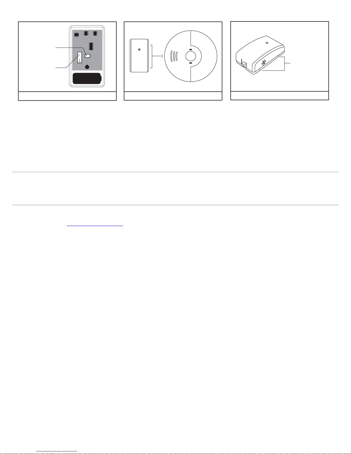
TEST BUTTON
BATT
TAMPER SWITCH
6” MAX
MARKINGS TO LINE
UP WITH EXISTING SMOKE
DETECTOR
IMAGE 1: TEST / TAMPER/ BUTTON IMAGE 2: INSTALLATION DISTANCE IMAGE 3: SIDE MARKINGS
INSTALLATION RECO M MENDATIONS
The FireFighter can be mounted within six inches away from any one of a number of hardwired interconnected smoke detectors. Careful consideration should
be made in identifying which smoke detector location will optimize performance and/or reduce the risk of other sound sources or sound distortion interfering in
the operation of the device.
• Install the FireFighter in the most isolated installation areas where an interconnected smoke detector is locat ed.
• To reduce the sound verification challenges that may occur with multiple uns ynchronized smoke alarms do not install the FireFighter next to a smoke
detector that is within six feet of another interconnected smoke detector.
• Avoid installing the FireFighter in areas where there may be a lot of sound echoing. (e.g. tiled flooring, walls, and ceilings)
This equipment should be installed in accordance with Chapter 2 of the National Fire Alarm Code, ANSI/NFPA 72, (National Fire Protection Association, Batterymarch Park, Quincy,
MA 02269). Printed information describing proper installation, operation, testing, maintenance, evacuation planning, and repair service is to be provided with this equipment. Warning:
Owner’s instruction notice: ’Not to be removed by anyone except occupant’.
SPECIFICATIONS
Frequency: 319.5 MHz Operating Temperature: 32°-120°F (0°-49°C) Battery: One 3Vdc
lithium CR123A (1550 mAh) Operating Humidity: 5-95% RH non condensing
Battery life: 5 years Works with any Interlogix Learn Mode Panel
Detection distance: 6 in (15 cm) max Supervisory signal interval: 64 min(approx.)
FCC, IC, and ETL listed in US and Canada to UL985 Maximum current draw: 23mA during transmission
CONTACT INFORMATION
www.interlogix.com
For customer support, see www.interlogix.com/support
PRODUCT ORDERING
Model
SLX-AD-T3 FireFighter Wireless Alarm Monitoring & Relay Device
Accessories
SM200-12PKG Smoke! In A Can (canned smoke) for functional testing of smoke alarms
FCC COMPLIANCE STATEMENT: FCC ID: XQC-WST-601 IC:11455A-ECFF319
This equipment has been tested and found to compl y with the limits for Class B digital devices, pursuant to Part 15 of the FCC Rules. These limits are designed to provide
reasonable protection against harmful interference in a residential installation. This equipment generates uses and can radiate radio frequency energy and, if not installed and used
in accordance with the instruction manual, may cause harmful interference to radio communications. However, there is no guarantee that interference will not occur in a particular
installation. If this equipment does cause harmful interference to radio or television reception, which can be determined by turning the equipment off and on, the user is encouraged
to try to correct the interference by one or more of the following measures:
• Re-orient or relocate the receiving antenna.
• Increase the separation between the equipment and receiver.
• Connect the equipment to an outlet on a different circuit from the receiver.
• Consult the dealer or an experienced radio/TV contractor for help.
This device complies with Industry Canada license-exempt RSS standard(s). Operation is subject to the following two conditions: (1) this device may not cause interference, and (2)
this device must accept any interference, including interference that may cause undesired operation of the device.
C’et appareil est conforme la norme d'Industrie Canada exempts de licence RSS. Son fonctio nnement est soumis aux deux conditions suivantes: (1) c’et appareil ne peut pas
provoquer d'interférences, et (2) c’et appareil doit accepter toute interférence, y compris les interférences qui peuvent causer un mauvais fonctionnement de la dispositif.
ADDITIONAL WARRANTY AND DISCLAIMER INFORMATION
THE FIREFIGHTER™ DETECTOR DOES NOT DETECT THE PRESENCE OF SMOKE, HEAT, OR FIRE DIRECTLY. IT RELIES SOLELY ON THE PRESENCE OF AN AUDIO
ALARM SIGNAL GENERATED BY AN EXISTING SMOKE OR FIRE DETECTOR IN PROXIMITY TO THE FIREFIGHTER™ DETECTOR TO MAKE SUCH A DETERMINATION. THE
FIREFIGHTER™ DETECTOR MUST BE USED WITH SMOKE DETECTORS CERTIFIED ACCORDING TO UL STANDARDS, AND IN STRICT ACCORDANCE WITH THE
INSTALLATION AND OPERATION INSTRUCTIONS PROVIDED WITH SUCH DETECTORS. IT IS THE OWNER’S RESPONSIBILITY TO ENSURE THAT SMOKE OR FIRE
DETECTORS USED IN CONJUNCTION WITH THE FIREFIGHTER™ DETECTOR ARE MAINTAINED AND TESTED ON A REGULAR BASIS IN ACCORDANCE WITH THE
MANUFACTURER’S INSTRUCTIONS. INTERLOGIX EXPRESSLY DISCLAIMS ANY RESPONSIBILITY FOR THE FAILURE OF THE FIREFIGHTER™ DETECTOR TO DETECT THE
PRESENCE OF SMOKE OR FIRE DUE TO THE FAILURE OF ANY SMOKE OR FIRE DETECTOR USED IN CONJUNCTION WITH THE FIREFIGHTER™ DETECTOR TO OPERATE
PROPERLY DUE TO ANY CONDITION, INCLUDING IMPROPER INSTALLATION, OPERATION, MAINTENANCE OR TESTING OF SUCH SMOKE OR FIRE DETECTOR.
MANUFACTURER HEREBY DISCLAIMS ALL WAR RANTIES AND REPRESENTATIONS, WHETHER EXPRESS, IMPLIED, STATUTORY OR OTHERWISE INCLUDING (BUT NOT LI MITED TO) ANY
WARRANTIES OF MERC HANTABILITY OR FITNESS FOR A PARTICULAR PURPOSE WITH RESPECT TO ITS FIREFIGHTER PRODUCTS AND RELATED SOFTWARE. MANUFACTURER FURTHER
DISCLAIMS ANY OTHER IMPLIED WARRANTY UNDER THE UNIFORM COMPUTER INF ORMATION TRANSACTIONS ACT OR SIMILAR LAW AS ENACTED BY ANY STATE.
(USA only) SOME STATES DO NOT ALLOW THE EXCLUSION OF IMPLIED WAR RANTIES, SO THE ABOVE EXCLUSION MAY NOT APPLY TO YOU. THIS WARRANTY GIVES YOU SPECIFIC LEGAL RIGHTS
AND YOU MAY ALSO HAVE OTH ER LEGAL RIGHTS THAT VARY FROM STATE TO STATE.
MANUFACTURER MAKES NO REPRESENTATIO N, WARRANTY, COVENANT OR PROMISE THAT ITS ALARM PRODUCTS AND/OR RELATED SOFTWARE (I) WILL NOT BE HACKED, COMPROMISED
AND/OR CIRCUMVENTED; (II) WILL PREVENT, OR PROVIDE ADEQUATE WARNING OR PROTECTION FROM, BREAK-INS, BURGLARY, ROBBERY, FIRE; OR (III) WILL WORK PROPERLY IN ALL
ENVIRONMENTS AND APPLICATIONS.
P/N 466-5233 • REV A • 13JAN16 © 2016 UTC Fire & Security Americas Corporation, Inc. All rights reserved.
 Loading...