

Page 1
EV1116 Series PIR Detector Installation Sheet
)
EN DA DE ES FI FR IT NL NO PL PT SV
1
3
4
2
(1)
(3)
16 m range (52 ft. 6 in.)
10 m (32 ft. 9 in.)
8 m (26 ft. 2 in.)
6 m (19 ft. 8 in.)
4 m (13 ft. 1 in.)
2 m (6 ft. 6 in.)
0 m
2 m (6 ft. 6 in.)
4 m (13 ft. 1 in.)
6 m (19 ft. 8 in.)
8 m (26 ft. 2 in.)
10 m (32 ft. 9 in.)
(optimum) 2.4 m
(7 ft. 10 in.)
1.2 m (3 ft. 11 in.)
4 m (13 ft. 1 in.)
2
m
(2)
16 (52 ft. 6 in.
.0 m
Note: For UL compliant installations please note an undercrawl
zone of 3 feet at minimum mounting height and 5 feet at
maximum mounting height.
© 2013 UTC Fire & Security Americas Corporation, Inc. 1 / 32 P/N 146251999-4 (ML) • REV D • ISS 12MAR13
All rights reserved.
Page 2
5
J6
J4
J3
EV1116
J1
EV1116AM
J4
J3
J6
J1
6
2 / 32 P/N 146251999-4 (ML) • REV D • ISS 12MAR13
Page 3

7
(1)
()2
EV1116
GND
+12V
Alarm
Alarm
Tamper
Ta m p e r
4
567
WT
D/N
8
J3
J4
J3
123
CP
Normal
< 33 Ω
larmA
8
Zone X
EV1116 EV1116AM
J3
J4
CP
Normal
larmA
Tam p er
Short
4.7 k
9.4
8
0
Ω
GND
+12V
123
Ω
kΩ
Alarm
Alarm
Ta m p e r
Tamper
567
4
Zone X
WT
J4
D/N
J3
8
J4
J3
GND
+12V
123
GND
+12V
123
Alarm
Alarm
Alarm
4
Alarm
4
Ta m p e r
Ta m p e r
567
Tamper
Tamper
567
WT
WT
D/N
J4
8
J3
CP
D/ND/N
8
Normal
larmA
Tamper
Short
AM/TF
EV1116AM
J4
CP
Normal
larmA
GND
+12V
Alarm
2
3
1
4.7 k
Ω
9.4
kΩ
88
0
Ω
< 33 Ω
8
Alarm
Tamper
5
4
Zone X
AM
Alarm
4
Zone X
Rtest
11
WT
D/N
AM
Ta m p e r
Ta m p e r
5
6
AM
Rtest
7
9
8
11
10
Zone Y
Alarm
3
Alarm
3
Alarm
Tamper
5
4
Alarm
Tamper
5
4
WT
D/N
AM
Ta m p e r
AM
Rtest
7
9
8
6
Ta m p e r
6
WT
7
11
10
D/N
AM
AM
Rtest
9
8
11
10
J3
J4
J4
J3
GND
1
GND
1
+12V
2
+12V
2
GND
+12V
Alarm
3
2
1
WT
D/N
AM
Ta m p e r
7
9
8
6
10
Zone Y
J4
J3
Normal
Ta mp er
Short
GND
+12V
Alarm
Alarm
Ta m p e r
Tamper
WT
567
123
4.7 k
9.4
0
Ω
kΩ
8
Ω
larmA
4
8
Zone X
EN: Installation Sheet
Introduction
The EV1116 series includes the EV1116 and EV1116AM PIR
motion sensors. They have a patented mirror, pyro and signal
processing technology.
Note: EV1116AM has not been evaluated by UL.
Installation guidelines
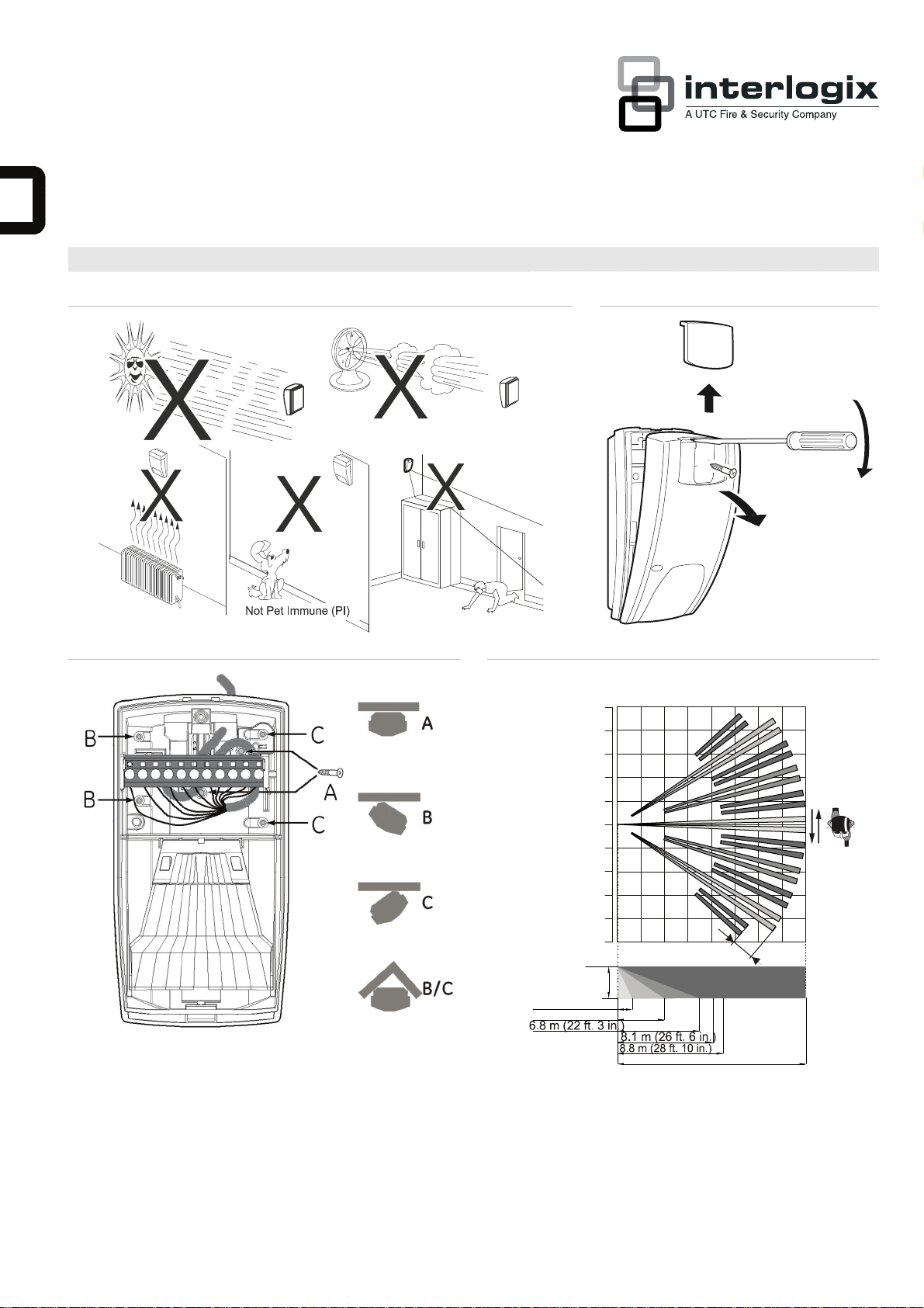
The technology used in these detectors resists false alarm
hazards. However, avoid potential causes of instability (see
Figure 1) such as:
• Direct sunlight on the detector
• Strong draughts onto the detector
• Heat sources within the detector field of view
• Animals within the detector field of view
• Obscuring the detector field of view with large objects,
such as furniture
• Objects within 50 cm (20 in.) of the anti-masking (AM)
detector
• Installing two detectors facing each other and less than
50 cm (20 in.) apart (only AM detectors)
J4
J3
GND
+12V
2
1
WT
D/N
Alarm
Alarm
3
4
AM
Ta m p e r
Ta m p e r
5
AM
Rtest
7
9
8
6
11
10
CP
4.7 k
9.4
0
Ω
kΩ
88
Zone X
Ω
Zone Y
Normal
larmA
Tamper
Short
AM/TF
Installing the detector
Figure 7 legend
Item Description
(1) Standard connection (factory default)
(2) Dual loop connection
CP Control panel
WT Walk test
AM Antimasking
D/N Day/night
Rtest Remote test
To install the detector:
1. Lift off the custom insert and remove the screw
(see Figure 2, step 1).
2. Using a screwdriver, carefully prise open the detector (see
Figure 2, steps 2 and 3).
3. Fix the base to the wall between 1.8 and 3.0 m (5.9 and
9.8 ft.) from the floor. For flat mounting use a minimum of
two screws (DIN 7998) in positions A. For corner-mounting
use screws in positions B or C (Figure 3). To install a pryoff tamper, use position A or C.
P/N 146251999-4 (ML) • REV D • ISS 12MAR13 3 / 32
Page 4

Note: Using the pry-off tamper has not been evaluated by
UL.
4. Wire the detector (see Figures 3 and 7).
UL installations: All wiring must be made according to
National Electrical Code, NFPA70, and CSA C22.1,
Canadian Electrical Code Part I, Safety Standards for
electrical Installations.
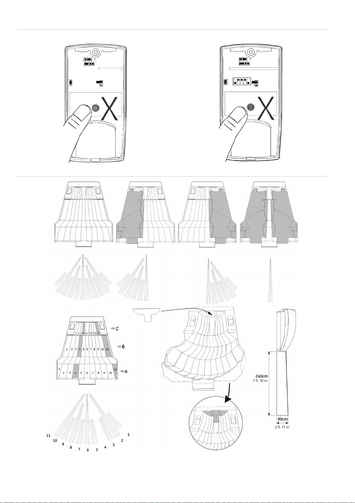
5. Select the desired jumper and DIP switch settings (see
Figure 5). See “Jumper settings” below for more
information.
Remove the blinders and add the stickers, if required (see
6.
Figure 6 for an example).
7. For ceiling-mount applications that require a 90° coverage
use the SB01 swivel-mount bracket.
Note: Using the swivel-mount bracket has not been
evaluated by UL. Ceiling mount application has not been
evaluated by UL.
8. Close the cover.
9. Insert the screw and place the custom insert.
For EN 50131 Grade 3 installations, do not use mounting
position B.
Jumper settings
See Figure 5 for the jumper locations in the detector.
J1: Mode jumper
Note: Bi-curtain jumper functionality is available in EV1116
with firmware version 1.13 or later, and in EV1116AM with
firmware version 1.21 or later.
On: BI-curtain mode. In this mode an extra level of processing
is applied to provide enhanced stability in the presence of false
alarm hazards. Bi-curtain is used to reduce the possibility of
false alarms. It looks for signal verification and requires the
intruder to be seen in two curtains.
This mode is not suitable for single curtain applications.
Off: Standard mode (default). This mode is suitable for most of
the wide angle and single curtain applications. The mode must
be used in EN 50131 compliant installations.
J3 and J4: Dual loop setting
This sets the alarm and tamper relays. It allows you to connect
the detector to any control panel. Use jumpers 3 and 4. See
Figure 7.
Use Remote Test (RT) to test the detector from the control
panel. The detector will activate the Alarm relay if the test
result is positive, and the AM relay if the test result is negative.
J6: Polarity setting of the control voltage (CV)
On (factory default):
• The detector is in Day mode (system disarmed) when the
D/N input is connected to GND (terminal 1)
• The detector is in Night mode (system armed) when the
D/N input is connected to +12 V (terminal 2)
• The detector is in Walk Test Off mode (LEDs are disabled)
when the WT input is connected to GND (terminal 1)
• The detector is on Walk Test On mode (LEDs are
enabled) when the WT input is connected to +12 V
(terminal 2)
Off:
• The detector is in Day mode (system disarmed) when the
D/N input is connected to +12 V (screw terminal 2).
• The detector is in Night mode (system armed) when the
D/N input is connected to GND (terminal 1).
• The detector is in Walk Test Off mode (LEDs are disabled)
when the WT input is connected to +12 V (terminal 2).
• The detector is on Walk Test On mode (LEDs are
enabled) when the WT input is connected to GND
(terminal 1).
D/N and WT functionality
The D/N input:
• Controls the LED functionality together with the WT input.
• Resets the alarm memory
• Controls the AM relay functionality during the NIGHT
mode together with SW1.
The WT input controls the LED functionality together with the
D/N input.
When the detector is in the Day mode and Walk Test On
mode, the LEDs of the detector can be activated. See “
ation” on page 5 for more information.
indic
During the Night mode the LE
Ds are always switched off.
LED
If a PIR intruder alarm if detected in the Night mode and the
detector switches back to Day mode, the red LED starts
flashing to indicate an alarm in memory.
The alarm memory is reset by switching the detector to Night
mode.
DIP switch settings
Factory default:
54321
ON
SW 1: When to signal AM (anti-masking) or TF (technical
fault) output
On: Signals AM or TF only when the system is in Day mode
(factory default).
Off: Always signals AM or TF during Day and Night mode.
SW 2: AM sensitivity
On: Selects a higher level of AM sensitivity. AM relay reacts
within 6 seconds.
Off: Selects the standard AM sensitivity. AM relay reacts within
12 seconds (factory default).
SW 3: Resetting the AM/TF output
The system will only reset an AM alarm if it has ensured that
the cause of the AM alarm has been removed. If the AM
circuitry cannot return to its original reference levels, then
either the detector is still masked or possibly has been
damaged. The owner should then visually check that the
detector is still fully functional.
On: Resets the AM or TF status 40 seconds after a PIR alarm.
Off: Resets the AM or TF status after a PIR alarm when the
system is in Day and Walk Test mode. The yellow LED will
blink quickly. When the system is in Night status, the yellow
LED will turn off and the system is reset (factory default).
SW 4: Signaling AM or TF output
On: Signals AM on both the AM and Alarm relays. Signals TF
on the AM relay only (EN 50131).
Off: Signals AM and TF on the AM relay (factory default).
4 / 32 P/N 146251999-4 (ML) • REV D • ISS 12MAR13
Page 5

SW 5: Setting LEDs
On: Enables both LEDs on the detector at all times (factory
default).
Off: Puts both LEDs under the control of the Walk Test and
EV1116 EV1116AM
Pry-off tamper (not
evaluated by UL/cUL)
AM relay characteristic — 80 mA at 30 VDC
Day/Night input. This activates the memory feature of the
detector.
LED indication
PIR Red LED Alarm relay To reset
Start up
Low voltage
PIR intruder
alarm
PIR/AM Red
LED
Start up
Low voltage
PIR intruder
alarm
Latched PIR
(Memory)
AM alarm
After AM reset
Technical fault
Continuously on Normal blinking (1 Hz)
Fast blinking (4 Hz)
* Depends on the setting of the DIP switch SW4.
Closed Automatically after 25 s
Open (Alarm) Apply correct voltage
Open (Alarm) Automatically after 3 s
Yellow
LED
Alarm
relay
Closed Closed Automatically
Open
(Alarm)
Open
(Alarm)
Switch to Night
Open*
(Alarm)
Switch to
Open
AM
relay
Open
(Alarm)
Automatically
Open
(Alarm)
(Alarm)
To reset
after 60 s
Apply correct
voltage
after 3 s
mode
See DIP
switch 3
Night mode
Do a successful
walk test
Specifications
EV1116 EV1116AM
Detector PIR PIR + AM
Signal processing DSP
Range 16 m
Optical 11 high-density mirror curtains
Memory Yes
Input power
For UL installations
Peak-to-peak ripple 2 V (at 12 VDC)
Detector start-up time 25 s 60 s
Normal current
For UL installations
Current in Alarm 2.5 mA 3.8 mA
Maximum current
(LED on)
Mounting height 1.8 m to 3.0 m (5.9 ft. to 9.8 ft.)
Target speed range 30 cm/s to 3 m/s
Alarm (NC) / Tamper relay
characteristic
9 to 15 VDC (12 V nominal)
10 to 15 VDC (12 V nominal)
5.5 mA
0.0528 mW
11.5 mA 24 mA
(1 ft./s to 10 ft./s)
20 cm/s to 3 m/s
80 mA 30 VDC, resistive
10 mA
—
(0.65 ft./s to
10 ft./s)
PIR alarm time 3 s
Operating temperature
For UL installations
Dimensions (H x W x D) 125 × 55 × 60 mm
Relative humidity 95% max. noncondencing
Weight 150 g
IP/IK rating IP30 IK02
Regulatory information
Manufacturer UTC Fire & Security Americas Corporation, Inc.
1275 Red Fox Rd., Arden Hills, MN 55112-6943, USA
Authorized EU manufacturing representative:
UTC Fire & Security B.V.
Kelvinstraat 7, 6003 DH Weert, The Netherlands
Certification
UL The product must be connected to a listed burglar
FCC Note: This equipment has been tested and found to
This device complies with part 15 of the FCC Rules.
system compatible control unit or power supply unit,
which provides a minimum 4 hours of standby power
and has a voltage output between 10 and 15 VDC.
All wiring must be made according to National
Electrical Code, NFPA70, and CSA C22.1, Canadian
Electrical Code Part I, Safety Standards for Electrical
Installations.
Perform walk test at least one per year.
Use only a listed power-limited supply.
EV1116AM has not been evaluated by UL.
comply with the limits for a Class B digital device,
pursuant to part 15 of the FCC Rules. These limits are
designed to provide reasonable protection against
harmful interference in a residential installation. This
equipment generates, uses and can radiate radio
frequency energy and, if not installed and used in
accordance with the instructions, may cause harmful
interference to radio communications. However, there
is no guarantee that interference will not occur in a
particular installation. If this equipment does cause
harmful interference to radio or television reception,
which can be determined by turning the equipment off
and on, the user is encouraged to try to correct the
interference by one or more of the following measures:
• Reorient or relocate the receiving antenna
• Increase the separation between the equipment
and receiver
• Connect the equipment into an outlet on a circuit
different from that to which the receiver is
connected
• Consult the dealer or an experienced radio/TV
technician for help
Operation is subject to the following two conditions:
(1) This device may not cause harmful interference,
and (2) this device must accept any interference
received, including interference that may cause
undesired operation.
Optional On-board (Yes)
max., resistive
−10 to +55°C (14 to 130°F)
0 to 49°C (32 to 120°F)
(4.92 x 2.16 x
2.36 in.)
(UL Installations)
125 × 65 × 60 mm
(4.92 x 2.6 x
2.36 in.)
P/N 146251999-4 (ML) • REV D • ISS 12MAR13 5 / 32
Page 6

2002/96/EC (WEEE directive): Products marked with
this symbol cannot be disposed of as unsorted
municipal waste in the European Union. For proper
recycling, return this product to your local supplier
upon the purchase of equivalent new equipment, or
dispose of it at designated collection points. For more
information see: www.recyclethis.info.
Contact information
www.utcfireandsecurity.com or www.interlogix.com
For customer support, see www.utcfssecurityproducts.eu
5. Vælg de ønskede jumper- og DIP-switch-indstillinger (se
figur 5). Se “Jumper-indstillinger” nedenfor, hvis du ønsker
erligere oplysninger.
yd
6. Fjern afskærmningen og påsæt klæbemærker efter behov
(se eksempel i Figur 6).
7. Til loftsmontering med 90 graders anvendelse benyttes
SB01-svingmonteringskonsol.
8. Luk frontlågen.
9. Isæt skruen og anbring dækpladen.
Til EN 50131 Grade 3-installationer må monteringsposition B
ikke anvendes.
DA: Installationsvejledning
Introduktion
EV1100-serien omfatter EV1116 og EV1116AM PIRrumdetektorer. De har patenteret spejl, pyro og
signalbehandlingsteknologi.
Installationsvejledning
Den anvendte teknologi i disse detektorer er modstandsdygtig
over for falske alarmer. Undgå imidlertid mulige årsager til
ustabilitet (se Figur 1), f.eks.:
• Direkte sollys på detektoren
• Kraftig træk på detektoren.
• Varmekilder inden for detektorens synsfelt
• Dyr inden for detektorens synsfelt
• Blokering af detektorens synsfelt med store genstande
som f.eks. møbler
• Genstand under 50 cm (20 in.) fra anti-maskeringsdetektor
(AM)
• Installation af to detektorer mod hinanden og mindre end
50 cm (20 in.) fra hinanden (kun AM-detektorer)
Installation af detektoren
Figur 7 symbolforklaring
Punkt Beskrivelse
(1) Standardtilslutning (fabriksstandard)
(2) Dobbelt sløjfe-tilslutning
CP Central
WT Gangtest
AM Antimaskning
D/N Dag/nat
Rtest Fjernbetj test
Sådan installeres detektoren:
1. Tag dækpladen af og fjern skruen (se Figur 2, trin 1).
2. Åbn forsigtigt detektoren med en skruetrækker (Figur 2,
trin 2 og 3).
3. Gør soklen fast til væggen mellem 1,8 og 3,0 m (5,9 og
9,8 ft.) fra gulvet. Til fladmontering anvendes mindst to
skruer (DIN 7998) i position A. Til hjørnemontering
anvendes skruer i position B eller C (Figur 3). Til at
installere vægsabotagekontakt anvendes position A
eller C.
4. Tilslut detektoren (se figur 3 og 7).
Jumper-indstillinger
Se jumpernes placeringer i detektoren i figur 5.
J1: Signalbehandling
Note: Jumper for Bi-curtain indstilling er muligt i EV1116 med
firmware version 1.13 eller nyere, og i EV1116AM med
firmware version 1.21 eller nyere.
Til: (Bi-Curtain): I denne indstilling vil en yderligere
signalbehandling give en forøget stabilitet i tilfælde af falske
alarmer ved vanskelige installationsmiljøer. Denne indstilling
bruges til reduktion af falske alarmer. Signalverifikation for
alarm kræver at en person passerer to gardiner.
Denne indstillng bør ikke benyttes ved korridordækning (kun
1 gardin).
Fra: Standard indstilling (Fabriksindstilling). Dette valg er for
alle normale installations-miliøer og ved korridordækning med
et enkelt gardin. Indstillingen skal bruges I EN 50131 krævede
installationer..
J3 og J4: Dobbelt løkkeindstilling
Bruges til indstilling af alarm- og sabotagerelæ. Den giver dig
mulighed for at tilslutte detektoren til et kontrolpanel. Brug
jumpers 3 og 4. Se Figur 7.
Brug fjerntest (RT) til at afprøve detektoren fra kontrolpanelet.
Detektoren aktiverer alarmrelæet, hvis testresultatet er positivt
og AM-relæet, hvis testresultatet er negativt.
J6: Polaritetsindstilling af kontrolspænding (CV)
Til (fabriksstandard):
• Detektoren er i dagtilstand (system frakoblet), når D/Ninput tilsluttes GND (terminal 1)
• Detektoren er i nattilstand (system tilkoblet), når D/N-input
tilsluttes +12 V (terminal 2)
• Detektoren er i tilstanden gangtest fra (LED er
deaktiveret), når WT-input tilsluttes GND (terminal 1)
• Detektoren er i tilstanden gangtest til (LED er aktiveret),
når WT-input tilsluttes +12 V (terminal 2)
Fra:
• Detektoren er i dagtilstand (system frakoblet), når D/Ninput tilsluttes +12 V (skrueterminal 2)
• Detektoren er i nattilstand (system tilkoblet), når D/N-input
tilsluttes GND (terminal 1).
• Detektoren er i tilstanden gangtest fra (LED er
deaktiveret), når WT-input tilsluttes +12 V (terminal 2)
• Detektoren er i tilstanden gangtest til (LED er aktiveret),
når WT-input tilsluttes GND (terminal 1)
D/N- og WT-funktionalitet
D/N-input:
• Styrer LED-funktionen sammen med WT-input.
6 / 32 P/N 146251999-4 (ML) • REV D • ISS 12MAR13
 Loading...