

Page 1
ESL 405
Polarity Reversal Relay Modules
U
L
LISTED
Installation Instructions
Description
ESL 405 polarity reversal relay modules are designed for use with ESL smoke
detectors that have built-in sounders. On alarm, the module disconnects the
detectors from their normal power supply and applies reverse polarity from the
notification appliance circuit. Applying reverse polarity causes the sounders on
detectors not in alarm to activate.
Application Notes
Use the following guidelines to determine the appropriate application of the relay
modules:
• For 2-wire applications, DO NOT connect pull stations, heat detectors or other
shorting devices.
• Use a single reversal module for 4-wire applications.
• For 2-wire applications, use one reversal module for each initiating circuit.
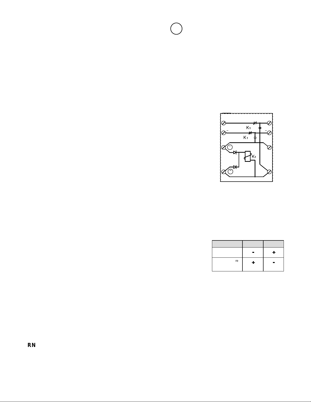
+
1
3
+
*
5
+
*
7
a
b
405-01 and 405-03
+
2
4
6
8
Installation
All wiring must conform to National Electrical Code (NEC) and/or local codes having
jurisdiction.
The module comes assembled for installation on a standard 4 inch commercial
electrical box.
Use the following instructions to install the module in a control panel:
1 . Slide the terminal/circuit board off the gray plastic mounting bracket.
2 . Remove the two screws holding the plastic mounting bracket to the metal plate.
3. Place double-sided adhesive tape on the back of the plastic mounting bracket and
stick the bracket inside the control panel enclosure.
4 . Slide the terminal/circuit board back into the plastic mounting bracket.
5. Strip 3/8” of insulation from each conductor and insert each one under the
appropriate screw terminal. Refer to the wiring diagrams for typical wiring
configurations.
6. Tighten the screws and check all wiring connections.
WARNING!
This device may not be compatible with all power supervision relays. When you
use this device on 4-wire circuits, use the ESL 204 series power supervision relay
at the end of line. An ESL smoke detector/alarm with a sounder that incorporates
an end-of-line/sensitivity relay output may also be used.
* Standby terminal connections:
noitacilppA 5lanimreT 7lanimreT
erifV42
lenaplortnoc
erif/yralgrubV21
lenap
-+
+-
lortnocdenibmoc
Page 2

Wiring Diagrams
Tw o Wire Diagram
Two wire
initiating
circuit
Notification
Appliance
Circuit
405-01
diagram
(24VDC)
1
3
5
7
ESL 405-01 (24VDC)
Polarity reversal relay
2
4
6
8
ESL 2 Wire Sounder
smoke detectors
Notification
Appliance
Circuit EOLR
First
detector
* Confirm compatibility when using powered and wire initiating devices.
Four Wire Diagram
Switched
smoke
power
Notification
Appliance
Circuit
405-01
diagram
(24VDC)
405-03
diagram
(12VDC)
12
3
5
7
ESL 405-03 (12VDC)
ESL 405-01 (24VDC)
Polarity reversal relay
4
6
8
Notification
Appliance
Circuit EOLR
ESL 4 Wire Sounder
smoke detectors
First
detector
Last
detector
Last
detector
End of
line device
End of
line
device
Initiating
Device
Circuit
Specifications
Voltage:
405-01 ..............................................................................20-30VDC
405-03 .............................................................................9.2-18VDC
Current:
405-01............................................................................21mA@24V
405-03............................................................................43mA@12V
Contacts...........................................................1A@30VDC resistive
Product Ordering
ledoM noitpircseD
10-504 e, UL & CSFMludomlasreverytiraloptiucricelgnis,CDV42
30-504 e, UL onlyludomlasreverytiraloptiucricelgnis,CDV21
Weight.....................................................................................0.02lbs.
Dimensions:
Height.........................................................................2.9” (7.3 cm)
Width..........................................................................2.1” (5.3 cm)
Depth.............................................................................1” (2.5 cm)
Listing.......................................................................................UL 864
15845 Rev B 02/01
 Loading...