

Page 1

ES3002-4P-4T User Manual
Power over Ethernet
Package contents
Thank you for purchasing the ES3002-4P-4T IFS 8-Port
10/100/1000T Gigabit Ethernet Switch with 4-Port 802.3at
PoE+ Injector.
Unless specified, the term “gigabit Ethernet switch”
mentioned in this user manual refers to the ES3002-4P-4T.
Open the box of the gigabit Ethernet switch and carefully
unpack it. The box should contain the following items:
• Gigabit ethernet switch × 1
• CD with user manual × 1
• Power cord × 1
• Rubber feet × 4
• 19” rack-mounting brackets with attachment screws × 1
If any of these pieces are missing or damaged, please contact
your dealer immediately. If possible, retain the carton including
the original packing material, and use them again to repack the
product in case there is a need to return it to us for repair.
Introduction
• Complies with IEEE 802.3af/at Power over Ethernet endspan PSE
• Up to four ports of IEEE 802.3af/802.3at devices powered
• Supports PoE power up to 30.8 W for each PoE port
• Each port supports 53 VDC power to PoE powered device
• 60 W PoE budget
• Auto detects powered device (PD)
• Circuit protection prevents power interference between
ports
• Remote power feeding up to 100 m with standard mode,
200 m with extended mode
Switching
• Hardware based 10/100/1000Mbps auto-negotiation and
auto MDI/MDI-X
• Flow control for full duplex operation and back pressure
for half duplex operation
• IEEE 802.1Q VLAN transparency
• Hardware DIP switch for “Standard” and “Extend” mode
selection; the “Extend” mode features 30 W PoE transmit
distance of 200 m at speed of 10 Mbps (only for Port1 –
Port4)
Hardware
Product description
To fulfill the demand of sufficient PoE power for network
applications with Gigabit speed transmission, the ES3002-4P-
4T 8-Port 10/100/1000T Gigabit Ethernet Switch with 4-Port
802.3at PoE+ Injector, a member of the 802.3at PoE Gigabit
Ethernet Switch family, features high-performance Gigabit
IEEE 802.3at PoE (up to 30 W) and a full 60 W PoE budget on
half of the switch’s eight 10/100/1000Mbps TP ports. The four
802.3at PoE+ ports provide a PoE power injector function that
can drive two IEEE 802.3at or 4 IEEE 802.3af compliant
powered devices. The ES3002-4P-4T also provides simple,
cost-effective, and non-blocking wire-speed performance with
an 8.5-inch metal housing suitable for desktop deployment for
SOHO and department network applications.
All RJ45 copper interfaces in the ES3002-4P-4T support
10/100/1000Mbps auto-negotiation for optimal speed detection
through RJ45 Category 6, 5, or 5e cables. It also supports
standard auto-MDI/MDI-X that can detect the type of
connection to any Ethernet device without requiring special
straight-through or crossover cables.
Features
Physical Port
• 8-port 10/100/1000BASE-T Gigabit Ethernet RJ45 copper
• 4-port IEEE 802.3at/af PoE Injector (Port-1 to Port-4)
• 8.5-inch desktop size, 1U height, rack mountable
• LED indicators for system power, per port PoE ready and
PoE activity, speed, Link/Act
• Fan-free design
• Supports Energy-Efficient Ethernet (EEE) function (IEEE
802.3az)
Specifications
Hardware specifications
Hardware version 2
10/100/1000BASE-T MDI/MDIX
ports
PoE Injector Port
Switch Architecture Store-and-Forward
Switch Fabric 16 Gbps/non-blocking
Switch Throughput@64 bytes 11.9 Mpps@64 bytes
MAC Address Table
8
Four ports with 802.3at/af PoE
injector function with Port-1 to Port-
4
4K entries, automatic source
address learning and aging
© 2017 United Technologies Corporation. P/N 1073337-EN • REV A • ISS 19JUL17
Interlogix is part of UTC Climate, Controls & Security, a unit of United Technologies Corporation. All rights reserved.
Page 2

Maximum Frame Size 9K bytes
T
IEEE 802.3x pause frame for full-
Flow Control
LED
DIP Switch
Dimensions (W × D × H) 135 × 87 × 32 mm
duplex
Back pressure for half-duplex
System:
Power (Green)
PoE max. (Green)
10/100/1000BASE-T RJ45
interfaces:
10/100Mbps LNK/ACT (Orange)
1000Mbps LNK/ACT (Green)
PoE interfaces:
PoE-in-Use (Orange)
Selectable operation mode
• Standard
• Extended
Environment
Temperature: 0 ~ 50°C
Operating
Storage
Relative Humidity: 5 ~ 95% (noncondensing)
Temperature: -10 ~ 70°C
Relative Humidity: 5 ~ 95% (noncondensing)
Description
These switches provide three different running speeds
(10 Mbps, 100 Mbps, and 1000 Mbps), and automatically
distinguish the speed of the incoming connection.
For easier management and control of the gigabit Ethernet
switch, become familiar with its display indicators and ports.
Front panel illustrations in this section show the unit LED
indicators. Read this section carefully before connecting any
network device to the gigabit Ethernet switch.
Enclosure Metal
Weight 929 g
Power requirements AC 100~240 V, 50/60 Hz, 2A max.
Power consumption/ dissipation Max. 65 W/223 BTU
Thermal fan None
Power over Ethernet
IEEE 802.3af Power over
PoE Standard
PoE Power Supply Type End-span
PoE Power Output
Power Pin Assignment 1/2(+), 3/6(-)
PoE Power Budget 60 W
Max. Number of Class 2 PDs 4
Max. Number of Class 3 PDs 4
Max. Number of Class 4 PDs 2
Standards conformance
Regulatory compliance FCC Part 15 Class A, CE
Standards Compliance
Ethernet/PSE
IEEE 802.3at Power over Ethernet
Plus/PSE
Per port 53 VDC, 600 mA.
max. 30 W
IEEE 802.3 10BASE-T
IEEE 802.3u 100BASE-TX
IEEE 802.3ab Gigabit 1000BASE-
IEEE 802.3x flow control and back
pressure
IEEE 802.3af Power over Ethernet
IEEE 802.3at Power over Ethernet
Plus
IEEE 802.3az Energy Efficient
Ethernet (EEE)
Front panel
The front panel of the gigabit Ethernet switch consists of eight
auto-sensing 10/100/1000Mbps Ethernet RJ45 ports. The LED
indicators are also located on the front panel of the gigabit
Ethernet switch.
Figure 1: ES3002-4P-4T front panel
The front panel of the gigabit Ethernet switch provides one DIP
switch for “Standard” and “Extended” mode selections.
Detailed descriptions are shown in the following table.
DIP switch mode Function
Standard
(default)
Extended
Numbers 1 to 4 correspond to PoE Port-1 to
Port-4.
In this mode, the gigabit Ethernet switch
operates as a general switch and all PoE
ports operate at 10/100/1000Mbps autonegotiation.
In this mode, the gigabit Ethernet switch PoE
ports operate at auto–negotiation 10Mbps
speed duplex mode only, but the delivery
distance of PoE power and network data can
reach 200 m.
2 / 8 P/N 1073337-EN • REV A • ISS 19JUL17
Page 3
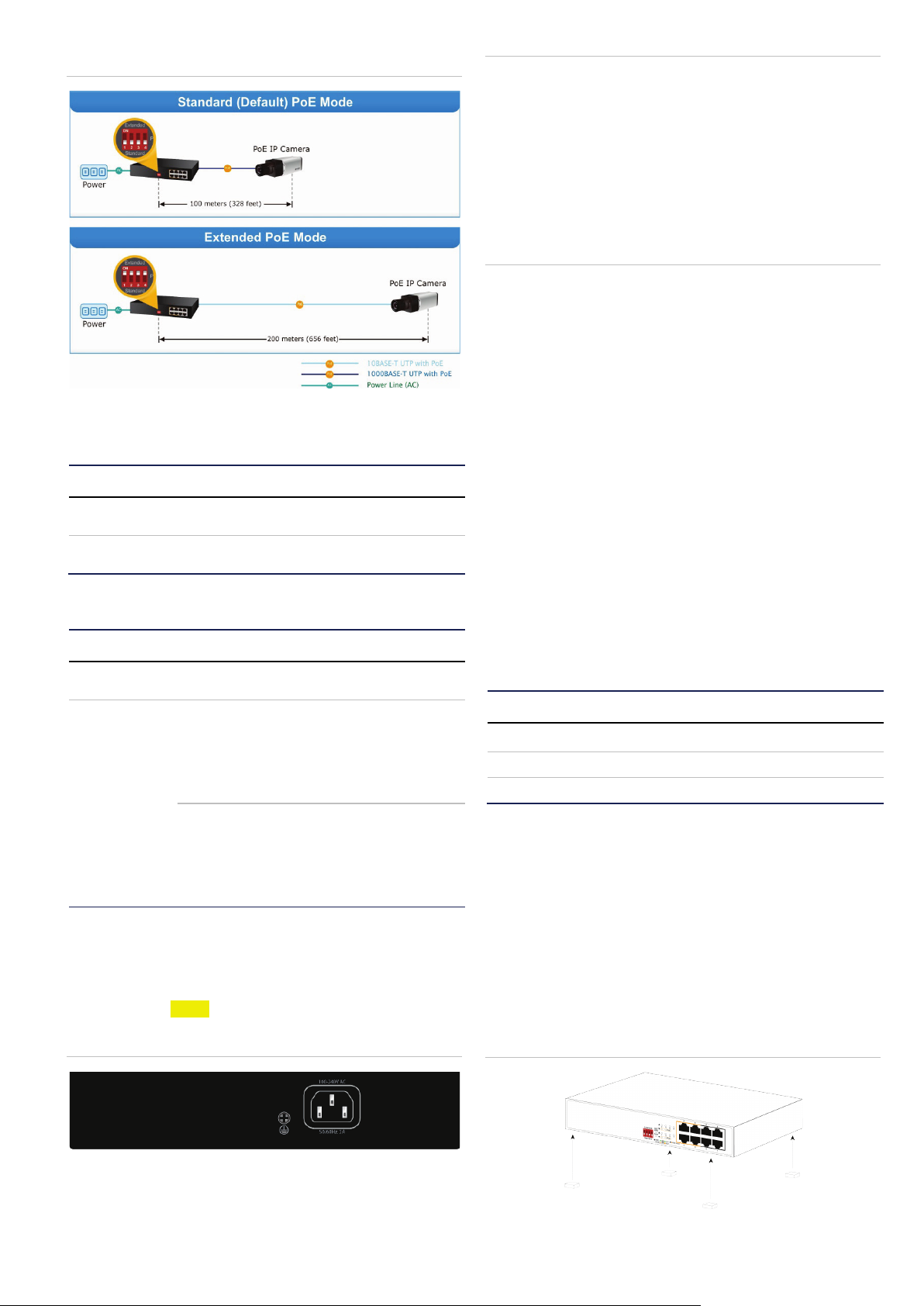
Figure 2: PoE modes
LED indicators
System
LED Color Function
PWR Green
POE MAX Green
Lit: indicates that the switch has
power.
Lit: indicates that the PoE usage is
full.
System per 10/100/1000 Mbps port
LED Color Function
PoE-in-use Orange
Green
Speed/LNK/ACT
Orange
Lit: indicates that the port is providing
53 VDC in-line power. (1-4 ports).
Lit: indicates that the switch is
successfully connecting to the
network at 1000 Mbps.
Blinking: indicates that the switch is
actively sending or receiving data
over that port.
Lit: indicates the port is successfully
connecting to the network at 100
Mbps or 10 Mbps.
Blinking: indicates that the switch is
actively sending or receiving data
over that port.
Note:
1. The gigabit Ethernet switch is a power-required device
which means it does not work unless power is applied. If
the network must be active at all times, consider using a
UPS (Uninterrupted Power Supply) for the gigabit Ethernet
switch. A UPS prevents network data loss or network
downtime.
2. In some areas, installing a surge suppression device may
also help to protect the gigabit Ethernet switch from being
damaged by an unregulated surge or current.
Installation
10/100/1000BASE-T
All 10/100/1000BASE-T ports come with auto-negotiation
capability. They automatically support 1000BASE-T,
100BASE-TX, and 10BASE-T networks. Users only need to
plug a working network device into one of the
10/100/1000BASE-T ports, and then turn on the gigabit
Ethernet switch. The port runs automatically in 10 Mbps,
20 Mbps, 100 Mbps, or 200 Mbps, and runs at 1000 Mbps or
2000 Mbps after negotiation with the connected device.
Cabling
Each of the 10/100/1000BASE-T ports uses RJ45 sockets for
the connection of unshielded twisted-pair cable (UTP). The
IEEE 802.3/802.3u/802.3ab Fast/Gigabit Ethernet standard
requires Category 5 UTP for 100Mbps 100BASE-TX. 10BASET networks can use Cat.3, 4, or 5; 1000BASE-T uses 5/5e/6
UTP (see the table below). Maximum distance is 100 meters
(328 feet).
Port type Cable type Connector
10BASE-T Cat.3, 4, 5, 2-pair RJ45
100BASE-TX Cat.5, 5e UTP, 4-pair
1000BASE-TX Cat.5/5e/6 UTP, 4-pair
Ethernet devices (hubs and computers, for example) can be
connected to the gigabit Ethernet switch by using straight-
through wires. The 10/100/1000Mbps ports are auto-MDI/MDIX and can be used with straight-through or crossover cables.
RJ45
RJ45
Desktop installation
Rear panel
The rear panel of the gigabit Ethernet switch consists of an AC
inlet power socket, which accepts input power from 100 to 240
VAC, 50-60 Hz, and a grounding screw.
Figure 3: ES3002-4P-4T rear panel
P/N 1073337-EN • REV A • ISS 19JUL17 3 / 8
Follow the steps below for gigabit Ethernet switch desktop
installation:
1. Attach the rubber feet to the recessed areas on the bottom
of the gigabit Ethernet switch as shown in Figure 4 below.
Figure 4: Attaching the rubber feet
Page 4

2. Place the gigabit Ethernet switch on the desktop near an
AC power source.
3. Provide adequate ventilation space between the gigabit
Ethernet switch and any surrounding objects.
Note: When choosing a location, consider the
environmental restrictions (airflow) detailed under
“Specifications” on page 1.
4. Connect the gigabit Ethernet switch to 802.3af/802.3at
compliant power devices (PD) or other network devices.
a. Connect one end of a standard network cable to the
10/100/1000BASE-T RJ45 ports on the front panel of
the gigabit Ethernet switch.
b. Connect the other end of the cable to a network device
such as a printer server, workstation, router, etc.
Note: Connection to the gigabit Ethernet switch requires
UTP Category 5, 5e, or 6 network cabling with RJ45
connectors. For more information, see “Appendix:
Networking connection” on page 7.
5. Supply power to the gigabit Ethernet switch.
a. Connect one end of the power cable to the gigabit
Ethernet switch.
b. Connect the power plug of the power cable to a
standard wall outlet.
After the gigabit Ethernet switch powers up, the power LED
illuminates solid green.
Rack mount installation
Follow the steps below to install the gigabit Ethernet switch in a
19-inch standard rack:
Figure 6: Rack mounting
5. Follow steps 4 and 5 under “Desktop installation” on page
3 to connect the network cabling and supply power to the
gigabit Ethernet switch.
Wall mount installation
1. Locate a wall suitable for mounting the ES3002-4P-4T.
2. Install two screws on the wall.
3. Hang the ES3002-4P-4T on the screws from the wall.
4. Follow step 5 under “Desktop installation” on page 3 to
power supply to the gigabit Ethernet switch.
Note: Before mounting the device to the wall, check the
location of the electrical outlet and the length of the
Ethernet cable.
Figure 7: Wall mounting
1. Place the gigabit Ethernet switch on a hard flat surface,
with the front panel positioned forward.
2. Attach a rack-mount bracket to each side of the gigabit
Ethernet switch with the supplied screws as shown in
Figure 5 below.
Figure 5: Attaching the brackets
3. Secure the brackets tightly.
4. After the brackets are attached to the gigabit Ethernet
switch, use suitable screws to securely attach the brackets
to the rack, as shown in Figure 6.
Product application
Connecting the end node or switch
1. Place the gigabit Ethernet switch on a smooth surface or
fasten the mounting brackets purchased separately with
the provided screws in a standard 19-inch rack.
2. Connect the power cord to the power inlet socket of the
gigabit Ethernet switch and the other end into the local
4 / 8 P/N 1073337-EN • REV A • ISS 19JUL17
Page 5

power source outlet. When the Switch receives power, the
Power LED illuminates solid green.
3. Connect the other switch or computer to one port of the
gigabit Ethernet switch using Category 3/4/5/5e/6
UTP/STP cabling.
4. Connect another switch or computer to the other port of
gigabit Ethernet switch by following the same process as
described in step 3 above.
Figure 8: End node or switch connection
PoE powered devices
Voice over IP phones
Enterprise can install PoE VoIP Phone, ATA
and other Ethernet/non-Ethernet end-devices
3~5 W
6~12 W
8~25 W
3~12 W
in the central area where UPS is installed for
an uninterruptible power and control system.
Wireless LAN Access Points
Museums, airports, hotels, scenic places,
campuses, factories, and warehouses can
install access points.
IP Surveillance
Enterprises, museums, campuses, hospitals,
and banks can install IP cameras without
restrictions on installation location as
electricians are not required to install AC
sockets.
PoE Splitter
A PoE Splitter is used to split the PoE
52 VDC over the Ethernet cable into
5/12 VDC power output.
It frees the device deployment from
restrictions due to power outlet locations,
which eliminate the costs for additional AC
wiring and reduces installation time.
Department/workgroup PoE+ switch
With 4 PoE+ in-line power interfaces, the ES3002-4P-4T can
provide central power to an IP phone system, IP camera
system, and a wireless AP group for the enterprise. For
example, up to four cameras can be installed for surveillance
demands or up to four wireless APs can be utilized to build a
wireless roaming environment in the office. Without a power
socket limitation, the Switch makes the installation of cameras
or wireless APs easy and efficient.
Figure 9: Department/workgroup PoE+ switch connection
Power over Ethernet (PoE) overview
What is PoE?
PoE technology comprises of a system that safely transmits
both power and data on an Ethernet UTP cable. The IEEE
standard for PoE technology requires a Cat5 or higher cable
for high power PoE levels, but can operate with a Cat3 cable
for low power levels. Power is supplied in common mode over
two or more of the differential pairs of wires found in the
Ethernet cables and comes from a power supply within a PoEenabled network device such as an Ethernet switch, or can be
injected into a cable run with a mid-span power supply.
The original IEEE 802.3af-2003 PoE standard provides up to
15.4 W of DC power (minimum 44 VDC and 350 mA) to each
device. Only 12.95 W is assured to be available at the powered
device as some power is dissipated in the cable.
The updated IEEE 802.3at-2009 PoE standard, also known as
PoE+ or PoE plus, provides up to 25.5 W of power. The 2009
standard prohibits a powered device from using all four pairs
for power. The 802.3af/802.3at defines two types of source
equipment: mid-span and end-span.
Mid-span
A mid-span device is placed between a legacy switch and the
powered device. Mid-span taps the unused wire pairs 4/5 and
7/8 to carry power; the other four are for data transmission.
End-span
An end-span device is directly connected to the powered
device. End-span can also tap the 1/2 and 3/6 wire pairs.
P/N 1073337-EN • REV A • ISS 19JUL17 5 / 8
Page 6

PoE system architecture
The specification of PoE typically requires two devices: the
Powered Source Equipment (PSE) and the Powered Device
(PD). The PSE is either an end-span or a mid-span, while the
PD is a PoE-enabled terminal, such as IP phones, wireless
LAN, etc. Power can be delivered over data pairs or spare
pairs of standard Cat5 cabling.
Powered Source Equipment (PSE)
Power sourcing equipment (PSE) is a device such as a switch
that provides (sources) power on the Ethernet cable. The
maximum allowed for continuous output power per cable in
IEEE 802.3af is 15.4 W. A later specification, IEEE 802.3at,
offers 25.50 W. When the device is a switch, it is commonly
called an end-span (although IEEE 802.3af refers to it as
endpoint). Otherwise, if it is an intermediary device between a
non PoE capable switch and a PoE device, it is called a midspan. An external PoE injector is a mid-span device.
Powered Device
A powered device (PD) is a device powered by a PSE and thus
consumes energy. Examples include wireless access points,
IP phones, and IP cameras. Many PDs have an auxiliary
power connector for an optional, external power supply.
Depending on the PD design, some, none, or all power can be
supplied from the auxiliary port, with the auxiliary port
sometimes acting as backup power in case of a PoE power
failure.
How power is transferred through the cable
A standard Cat5 Ethernet cable has four twisted pairs, but only
two of these are used for 10BASE-T and 100BASE-TX. The
specification allows two options for using these cables for
power, shown in Figure 10 and Figure 11.
The spare pairs are used. Figure 10 below shows the pair on
pins 4 and 5 connected together and forming the positive
supply, and the pair on pins 7 and 8 connected and forming the
negative supply (either polarity can be used).
Figure 10: Power supplied over spare pins
The data pairs are used. Since Ethernet pairs are transformers
coupled at each end, it is possible to apply DC power to the
center tap of the isolated transformer without disrupting the
data transfer. In this mode of operation, the pair on pins 3 and
6 and the pair on pins 1 and 2 can be of either polarity.
Figure 11: Power supplied over the data pins
Troubleshooting
This section contains issue-solving information. If the gigabit
Ethernet switch is not functioning properly, ensure that it was
set up according to the instructions in this manual.
Issue Solution
The link LED does not
illuminate.
The 1000BASE-T port link
LED illuminates, but the
traffic is irregular.
The gigabit Ethernet switch
isn’t connected to the
network
A PoE device connected to
the gigabit Ethernet switch
is not receiving power
How can the power output of
each PoE port be
determined?
Check the cable connection and
try swapping out a cable.
Ensure that the attached device is
not set to full duplex. Some
devices use a physical or software
switch to change duplex modes.
Auto-negotiation may not
recognize this type of full-duplex
setting.
Check the LNK/ACT LED and/or
try another port on the gigabit
Ethernet switch. Ensure that the
cable is installed properly and is
the correct type. Turn off the
power and then, after a while, turn
on the power again.
• Check the cable type making
the connection to the device.
The cable should be an 8-wire
UTP, Cat5 or above, and
EIA568 cable within 100
meters. A 4-wire, short loop
cable, or a cable over 100
meters, affects the power
supply.
• Ensure that the device is fully
compliant with IEEE
802.3af/IEEE 802.3at
standards.
• Each PoE port supports 53 V54 DC, 600 mA, and a
maximum of 30 W of power
output. Detect and inject by the
IEEE 802.3at standard.
• Each PoE port supports 53 V54 DC, 300 mA and a
maximum of 15.4 W of power
output. Detect and inject by the
IEEE 802.3af standard.
6 / 8 P/N 1073337-EN • REV A • ISS 19JUL17
Page 7

Appendix: Networking
Straight-through Cable
SIDE 1
SIDE 2
SIDE 1
1 = White / Orange
1 = White / Orange
SIDE 2
Crossover Cable
SIDE 1
SIDE 2
SIDE 1
1 = White / Orange
1 = White / Green
SIDE 2
1 2 3 4 5 6 7 8
1 2 3 4 5 6 7 8
1 2 3 4 5 6 7 8
1 2 3 4 5 6 7 8
connection
RJ45 pin assignments
1000Mbps, 1000BASE-T
Contact MDI MDI-X
1 BI_DA+ BI_DB+
2 BI_DA- BI_DB-
3 BI_DB+ BI_DA+
4 BI_DC+ BI_DD+
5 BI_DC- BI_DD-
6 BI_DB- BI_DA-
7 BI_DD+ BI_DC+
8 BI_DD- BI_DC-
Implicit implementation of the crossover function within a
twisted-pair cable or at a wiring panel, while not expressly
forbidden, is beyond the scope of this standard.
10/100Mbps, 10/100BASE-TX
When connecting the gigabit Ethernet switch to another Fast
Ethernet switch, a straight-through or crossover cable might be
necessary. Each port of the gigabit Ethernet switch supports
auto-MDI/MDI-X detection, which enables direct connection to
any Ethernet device without making a crossover cable. The
following table and diagram show the standard RJ45
receptacle/connector and their pin assignments:
RJ45 connector pin assignment
MDI
Contact
1 Tx + (transmit) Rx + (receive)
2 Tx - (transmit) Rx - (receive)
3 Rx + (receive) Tx + (transmit)
4, 5 Not used
6 Rx - (receive) Tx - (transmit)
7, 8 Not used
Media Dependent
Interface
MDI-X
Media Dependent
Interface -Cross
The standard RJ45 receptacle/connector
There are eight wires on a standard UTP/STP cable and each
wire is color-coded. Figure 12 below shows the pin allocation
and color of straight-through cable and crossover cable
connection.
Figure 12: Straight-through and crossover cable
2 = Orange
3 = White / Green
4 = Blue
5 = White / Blue
6 = Green
7 = White / Brown
8 = Brown
2 = Orange
3 = White / Green
4 = Blue
5 = White / Blue
6 = Green
7 = White / Brown
8 = Brown
2 = Orange
3 = White / Green
4 = Blue
5 = White / Blue
6 = Green
7 = White / Brown
8 = Brown
2 = Green
3 = White / Orange
4 = Blue
5 = White / Blue
6 = Orange
7 = White / Brown
8 = Brown
Ensure that the connected cables have the same pin assignment and color as described above before deploying them in a
network.
P/N 1073337-EN • REV A • ISS 19JUL17 7 / 8
Page 8

Regulatory information
Manufacturer
FCC compliance
communications. Operation of this equipment in a
FCC conditions
ACMA compliance
Canada
This Class A digital apparatus complies with CAN
Certification
European Union
directives
unsorted municipal waste in the European Union.
Trademarks and
patents
North America
T
E
W
Latin America
T
E
Europe, Middle East, and Africa
W
Australia
E
Interlogix.
2955 Red Hill Avenue, Costa Mesa, CA 92626
5923, USA
Authorized EU manufacturing representative:
UTC Fire & Security B.V.
Kelvinstraat 7, 6003 DH Weert, The Netherlands
Class A: This equipment has been tested and
found to comply with the limits for a Class A
digital device, pursuant to part 15 of the FCC
Rules. These limits are designed to provide
reasonable protection against harmful
interference when the equipment is operated in a
commercial environment. This equipment
generates, uses, and can radiate radio frequency
energy and, if not installed and used in
accordance with the instruction manual, may
cause harmful interference to radio
residential area is likely to cause harmful
interference in which case the user will be
required to correct the interference at his own
expense.
This device complies with Part 15 of the FCC
Rules. Operation is subject to the following two
conditions:
(1) This device may not cause harmful
interference.
(2) This Device must accept any interference
received, including interference that may cause
undesired operation.
Notice! This is a Class A product. In a domestic
environment this product may cause radio
interference in which case the user may be
required to take adequate measures.
ICES-003 (A)/NMB-3 (A).
Cet appareil numérique de la classe A est
conforme à la norme CAN ICES-003 (A)/NMB-3
(A).
This product complies with the applicable
harmonized European standards listed under the
EMC Directive 2014/30/EU, the RoHS Directive
2011/65/EU.
2012/19/EU (WEEE directive): Products marked
with this symbol cannot be disposed of as
For proper recycling, return this product to your
local supplier upon the purchase of equivalent
new equipment, or dispose of it at designated
collection points. For more information see:
www.recyclethis.info.
The trade names used in this document may be
trademarks or registered trademarks of the
manufacturers or vendors of the respective
products.
Contact information
+1 855.286.8889
techsupport@interlogix.com
www.interlogix.com/support
+1 561-998-6114
latam@interlogix.com
Select Contact Us at www.utcfssecurityproducts.eu
security.tech.support@interlogix.com.au
8 / 8 P/N 1073337-EN • REV A • ISS 19JUL17
 Loading...