


TruVision DVR 42 User
Manual
P/N 1072662B-EN • REV 1.0 • ISS 13AUG14
Copyright
©
Interlogix is part of UTC
Technologies Corporation. All
Trademarks and
patents
Trade names
trademarks of the manufacturers or vendors of the respective products.
Manufacturer
Interlogix
2955 Red Hill Avenue, Costa Mesa, CA 92626
Authorized EU manufacturing represent ative:
UTC Fire & Security B.V.
Kelvinstraat 7, 6003 DH Weert, The Netherland s
Certification
FCC compliance
Class A: This equipment has been tested and found to comply with the limits for
a Class A digital device, pursuant to part 15 of the FCC Rules. These limits are
designed to provide reasonable protection against harmful interference when
the equipment is operated in a commercial environment. This equipment
generates, uses, and can radiate radio frequency energy and, if not installed
and used in accordance with the instruction manual, may cause harmful
interference to radio communications. Operation of this equipment in a
residential area is likely to cause harmful interference in which case the user will
be required to correct the interference at hi s own ex pense.
ACMA compliance
Notice! This is a Class A product. In a domestic environment this product may
cause radio interference in which case the user may be required to take
adequate measures.
Canada
This Class A digital apparatus complies with Canadian ICES
Cet appareil numérique de la class A conforme à la norme NMB-003 du
Canada.
European Union
directives
12004/108/EC (EMC directive):
declares tha
or with the essential requirements and
other relevant provisions of Directive 2004/108/EC
2002/96/EC (WEEE directive):
disposed of as unsorted municipal waste i n the European Union. For proper
recycling, return this product to your local sup pl i er upon the purchase of
equivalent new equipment, or dispose of it at designated collect
more information see: www.recyclethis. i nfo.
2006/66/EC (battery directive):
disposed of as unsorted municipal waste i n the European Union. See the
product documentation for specific battery
with this symbol, which may include lettering t o i ndicate cadmium (Cd), lead
(Pb), or mercury (Hg). For proper recycli ng, return the battery to your supplier or
to a designated collection point. For more information see:
Contact information
For contact information
www.utcfssecurityproducts.eu
2014 United Technologies Corporation.
Buildings & Industrial Systems, a unit of Unit ed
rights reserved.
used in this document may be trademarks or regi st ered
.
-5923, USA
N4131
t this device is in compliance
Products marked with this symbol cannot be
-003.
Hereby, UTC Climate Controls & Se curity
.
ion points. For
This product contains a battery that cannot be
information. The battery is marked
www.recyclethis.info.
, see www.interlogix.com or

Content
Chapter 1 Product introduction 5
Product overview 5
Default settings to access the device 5
Chapter 2 Installation 7
Installation environment 7
Unpacking the TVR 42 and its accessories 7
Back panel 8
RS-485 ports 9
RS-232 port 10
Monitor connections 10
Loop through 10
Audio inputs and output 10
Brackets 11
PTZ dome camera set up 11
Wiring the KTD-405 keypad 16
Chapter 3 Getting started 19
Turning on and off the DVR 19
Using the setup wizard 20
Chapter 4 Operating instructions 24
Controlling the TVR 42 24
Using the front panel 24
Using the mouse 27
Using the IR remote control 28
Menu overview 30
Chapter 5 Live view 33
Description of live view 33
Video output 34
Audio output 34
Controlling live view 34
Multiview format 36
Sequencing cameras 37
Accessing frequently used commands 37
Configuring live view 39
Configuring time and date 42
General settings 43
V-stream encoding 46
Chapter 6 Controlling a PTZ camera 47
Configuring PTZ settings 47
Calling up presets, preset tours and shadow tours 48
TruVision DVR 42 User Manual 1

Setting and calling up presets 49
Setting and calling up preset tours 51
Setting and calling up a shadow tour 52
Chapter 7 Playing back a recording 54
Overview of the playback window 54
Playback pop-up menu 56
Instant playback 57
Previous-day playback 58
Searching recorded video 59
Playing back recordings by time and video type 60
Playing back recordings by event 61
Creating and playing back bookmarked recordings 62
Slideshow of snapshots 63
Playing back recordings from the system log 64
Playback skip time 65
Motion search 65
Playing back frame-by-frame 66
Digital zoom in playback 66
Chapter 8 Archiving recorded files 67
Archiving files 67
Auto archiving 70
Creating and archiving video clips 71
Archiving snapshots 72
Managing backup devices 72
Playing back archived files on a PC 72
Chapter 9 Using the web browser 73
Windows Vista and 7 users 73
Accessing the web browser 74
Web browser overview 74
Using the web browser to configure the device 76
Searching and playing back recorded video 80
Searching for event logs 82
Dual streaming 82
Controlling a PTZ dome camera in the web browser 84
Capturing text insertions 84
Text overlay 86
Using a network storage system 87
Chapter 10 Recording 89
Initializing recording settings 89
Defining a recording schedule 93
Daily schedules 94
Holiday schedules 95
Manual recording 95
Motion detection schedules 96
2 TruVision DVR 42 User Manual

External alarm schedules 96
Protecting recorded files 96
HDD redundancy 98
Chapter 11 Alarm settings 100
Description of alarm notification types 100
Setting up motion detection 103
Setting up external alarms 106
Triggering or clearing alarm outputs manually 108
Setting up system notifications 108
Detecting video loss 109
Detecting video tampering 110
Chapter 12 Network settings 111
Configuring general network settings 111
Configuring PPPoE 112
Configuring DDNS 113
Configuring an NTP server 114
Configuring e-mail 114
Configuring UPnP 115
Configuring SNMP 116
Configuring an FTP server to store snapshots 116
Configuring a remote alarm host 117
Configuring multicast 117
Configuring the server and HTTP ports 117
Configuring the RTSP service port 118
Checking network status 118
Exporting network packet data 119
Bandwidth throttle management 120
Chapter 13 HDD management 121
Initializing HDDs 121
Controlling disk space on the HDD 121
Setting up HDD groups 122
Recording dual streaming 123
Setting the HDD property 123
Checking HDD status 124
Configuring HDD alarms 124
Managing eSATA 125
Checking the S.M.A.R.T. information 125
Searching video using disk analysis 126
Chapter 14 Camera settings 128
Configuring the camera OSD settings 128
Setting up privacy masking 129
Adjusting camera image settings 130
Watermarking 130
Hiding a camera image from view 130
TruVision DVR 42 User Manual 3

Chapter 15 DVR management 132
Configuring the RS-232 port 132
Updating system firmware 133
Restoring default settings 134
Viewing system information 134
Searching system logs for events 137
Importing and exporting configuration settings 138
Chapter 16 User management 139
Adding a new user 139
Customizing a user’s access privileges 140
Deleting a user 142
Modifying a user 142
Changing the Admin password 142
Appendix A Specifications 143
Appendix B PTZ protocols 145
Appendix C Port forwarding information 146
Appendix D KTD-405 keypad 148
Supported firmware 148
Wiring the keypad 148
Setting up the keypad to work with the TVR 42 149
Operating the keypad 151
Appendix E Maximum pre-recording times 156
Appendix F Supported PTZ commands 158
Appendix G Default menu settings 160
Index 171
4 TruVision DVR 42 User Manual

User
Administrator
Operator
Chapter 1
Product introduction
Product overview
The TruVision™ DVR 42 (TVR 42) is a versatile, user-friendly embedded digital
video recorder (DVR) allowing end-users to record 4, 8, or 16 analo g c am eras at
960h in real time (25/30 fps), while providing integration with the UTC portf olio of
security solutions, and offering a seamless product experience within the
TruVision brand.
Its dual streaming functionality allows the user to set up different settings for
recording and streaming video in live view mode.
TruVision DVR 42 can fully integrate with the license-free TruVision Navigator
software, which is ideal for the most commercial applications. TVR 42’s easy and
intuitive-to-use web browser interface enables remote configuration and secur e
viewing, searching, and playing back of video from computers connected via the
Internet.
Note: Models are shipped with the power chords for their region.
Default settings to access the device
Default user names and passwords
See Table 2 below for the list of default user names and passwords. Go to
Chapter 16 “User management” on page 139 for further information.
Table 1: Default user names and pass words
Description
There can only be one administrator.
The user name is admin. The name cannot be modified.
The default password is 1234.
The default user name is “operator”.
The default password is 2222.
TruVision DVR 42 User Manual 5

User
Guest
HTTP port: 80
Server/Client software port: 8000
Description
The default user name is “guest”.
The default password is 3333.
Note: The default passwords should be changed for security reasons.
Default network settings
The default values for TVR 42 network settings are:
• IP address - 192.168.1.82
• Subnet mask - 255.255.255.0
• Gateway address - 192.168.1.1
• Ports:
When using the browser:
RTSP port: 554
When using TruNav:
RTSP port: 554
Go to Chapter 9 “Using the web browser” on page 73 for further information.
6 TruVision DVR 42 User Manual

Chapter 2
Installation
This section describes how to install the TVR 42 unit.
Installation environment
When installing your product, consider these factors:
• Ventilation
• Temperature
• Moisture
• Chassis load
Ventilation: Do not block any ventilation openings. Install in accordance with the
manufacturer’s instructions. Ensure that the location planned for the installation
of the unit is well ventilated.
Temperature: Consider the unit’s operating temperature (-10 to +55 ºC, 14 to
131 °F) and noncondensing humidity specifications (10 to 90%) before choosing
an installation location. Extremes of heat or cold beyond the specified operating
temperature limits may reduce the life expectancy of the DVR. Do not install the
unit on top of other hot equipment. Leave 44 mm (1.75 in.) of space between
rack-mounted TruVision DVR 42 units.
Moisture: Do not use the unit near water. Moisture can damage the internal
components. To reduce the risk of fire or electric shock, do not expose this unit to
rain or moisture.
Chassis: Equipment weighing less than 15.9 kg (35 lb.) may be placed on top of
the unit.
Unpacking the TVR 42 and its acce ssories
When you receive the product, check the package and contents for damage, and
verify that all items are included. There is an item list included in the package. If
any of the items are damaged or missing, please contact your local supplier.
TruVision DVR 42 User Manual 7

Items shipped with the product include:
• IR (infrared) remote control
• Two AAA batteries for the remote control
• AC power cords (US, Europe, UK)
• USB mouse
• TVR 42
• Video loop through cable
• CD with software and manuals
• TruVision DVR 42 Quick Start Guide
• TruVision DVR 42 User Manual (on CD)
• TruVision Recorder Operator Guide (on CD)
Back panel
Figure 1 on page 9 shows the back panel connections and describes each
connector on a typical TVR 42 digital video recorder. Details may vary for specific
models.
Before powering up the DVR, connect the cameras and a main monitor for basic
operation.
8 TruVision DVR 42 User Manual
supports both digital audio and video.
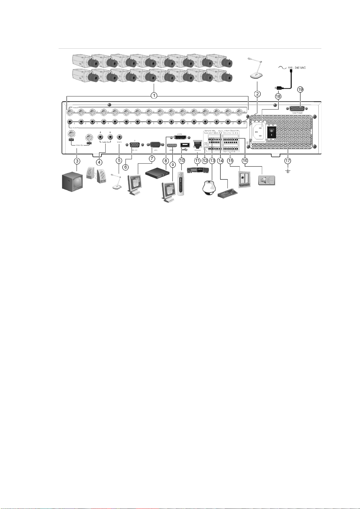
Figure 1: Back panel connections
1. Connect up to 16 analog cameras to BNC
connectors (depends on the DVR model).
2. Connect audio inputs (available for each
camera) to RCA connectors.
3. Connect up to two CCTV monitors (BNCtype connectors):
- Spot monitor
- Main monitor
4. Connect to speakers for audio output.
5. Connect RCA connector to a m i cr ophone.
6. Connect to a RS-232 device.
7. Connect one CCTV monitor (BNC-type
connector).
8. Connect to an optional eSATA device such
as SATA HDD, CD/DVD-RM.
9. Connect to a HDTV. The HDMI connection
10. Connect to an optional USB device such as
a mouse, CD/DVD burner or HDD. The
DVR supports both a USB DVD and a USB
HD on the front and back USB ports.
11. Connect to a network.
12. Terminate the line to the dome cameras
using this RS-485 switch. Default is Off.
13. Connect to a PTZ control.
14. Connect to a keyboard (KTD-405 shown)
15. Connect up to 16 alarm inputs.
16. Connect up to four alarm relay outputs.
17. Connect to ground.
18. Connect to a power supply.
19. Loop through for up to 16 analog cameras
(see item 1).
RS-485 ports
There are two RS-485 ports on the back panel of the DVR. See Figure 2 on page
10 for the serial pin outs.
• Dome RS-485:
A and B: Connect pan, tilt, zoom control of PTZ dome cameras. A = +, B = C and D: Not used
TruVision DVR 42 User Manual 9
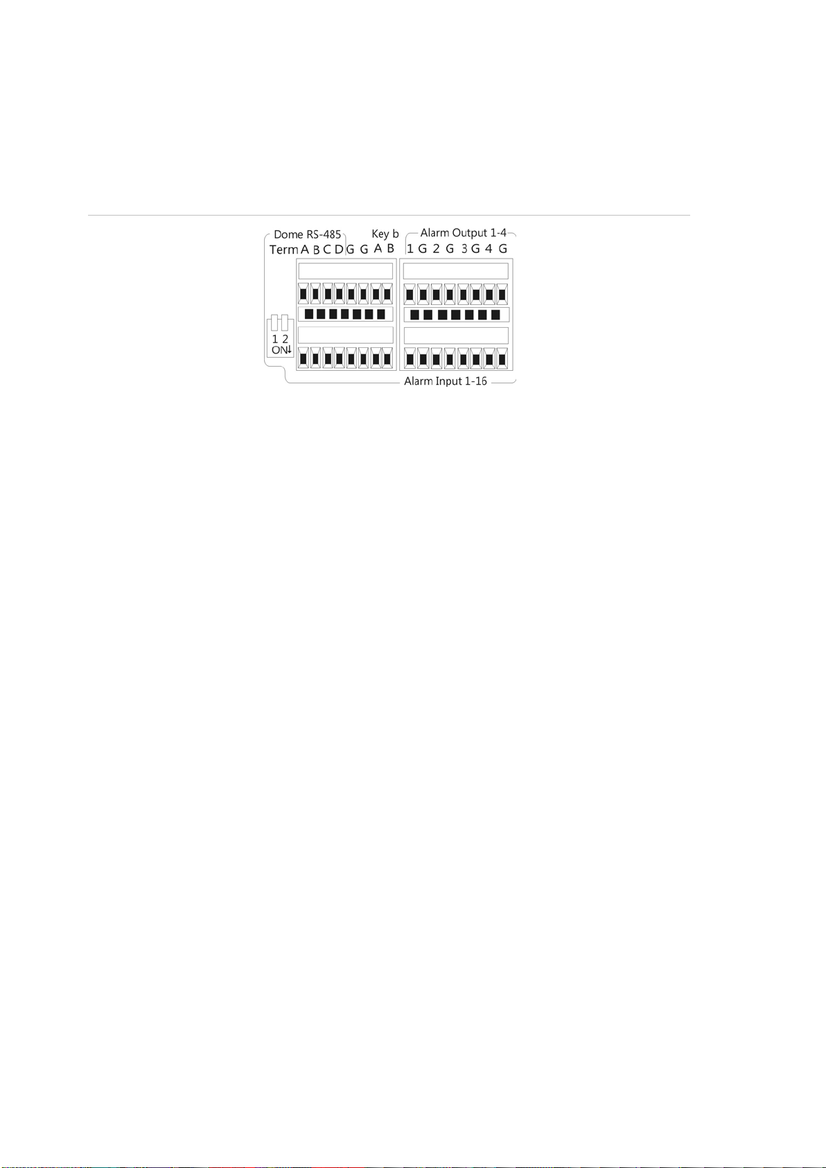
G: Ground of dome camera
G: Ground of keypad
• Keyb: Connect the keypad.
Figure 2: RS-485 pins
RS-232 port
Use the RS-232 port to connect CBR-PB3-POS (point-of-sale) and ATM devices
to the DVR. See “Configuring the RS-232 port” on page 132 to configur e the port.
Monitor connections
Connect the monitors to the DVR outputs (BNC/VGA/HMDI). The HDMI version
is 1.3. The unit provides a 1 Vp-p analog signal. See Figure 1 on page 9 for
connecting a monitor to a TVR 42.
The TVR 42 supports up to 1280 × 1024 / 60 Hz resolution in VGA. The monitor
resolution should be at least 800 × 600. Adjust your monitor accordingly to this
resolution.
Loop through
You can loop through the cameras to equipment such as a matrix, monitors or a
second DVR. There are 16 numbered loop-through BNC outputs. See Figure 1
on page 9.
Audio inputs and output
The unit is equipped with 16 audio inputs and two audio outputs. Both the audio
output and the audio inputs are line-level. Each 16 audio input is associated with
one of the 16 cameras.
10 TruVision DVR 42 User Manual
Audio input
Audio output
RCA jack, 315 mV, 40 kohms. Unbalanced
RCA jack, 315mV, 600 ohms. Unbalanced
Note: Line-level audio requires amplification.
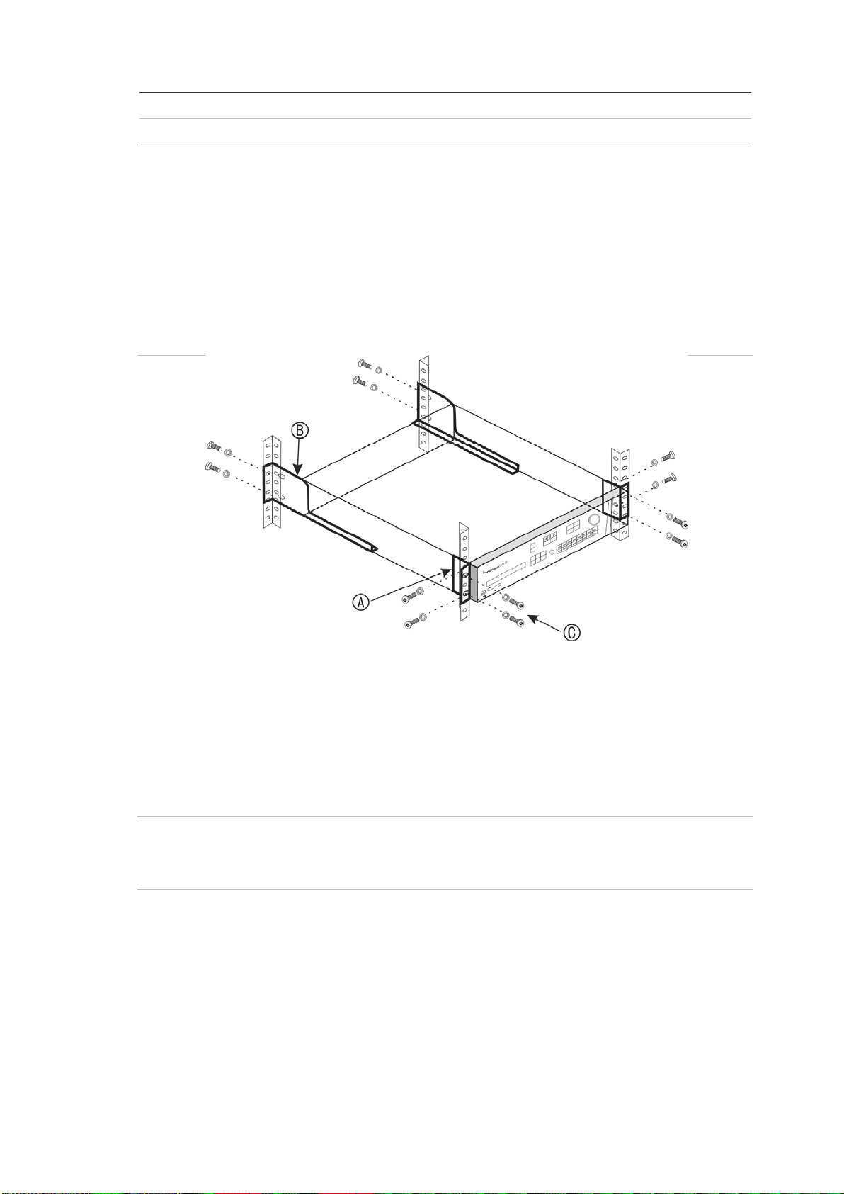
Brackets
The DVR is easily rack-mountable with the purchase of the TVR-RK-1 r ac kmount kit. See Figure 3 below. Contact your local supplier to order it.
Figure 3: Rack-mount installation
To install the racks:
1. Attach the two small front-rack mount ears to the DVR (A). The screws are
supplied.
2. Attach the two large rear support brackets (not supplied) to the rear rails (B).
3. Attach the DVR to the front rails (C). The screws are not supplied.
Caution:
Do not rack-mount the TVR 42 without the rear rails installed. Failure to install
the rear rails can damage the DVR.
PTZ dome camera set up
Use the USB mouse provided or the optional keypad for local telemetry control. If
using the TVR 42 over a network, use the web browser to control the PTZ dome
cameras or TruVision Navigator.
TruVision DVR 42 User Manual 11
See Appendix B on page145 for the supported protocols and Appendix F on
page 158 for the PTZ commands supported by each protocol.
Each PTZ camera must be set up individually. For information on configuring
PTZ dome camera settings, see Chapter 6, “Controlling a PTZ camera” on page
47.
Connecting a TVR 42 to a PTZ dome camera and a
keypad
You can connect the KTD-405 or TVK-800 keypad to the DVR. The KTD-405 is a
RS-485 bus keypad and the TVK-800 is an IP keypad.
For information on using the TVK-800 keypad, please refer to the TVK-800 user
manual.
When connecting the KTD-405 keypad, use the input/output box that is supplied
with the keypad to connect a keypad to the TVR 42. The keypad can be
connected to a PTZ camera for local control or for control over the network.
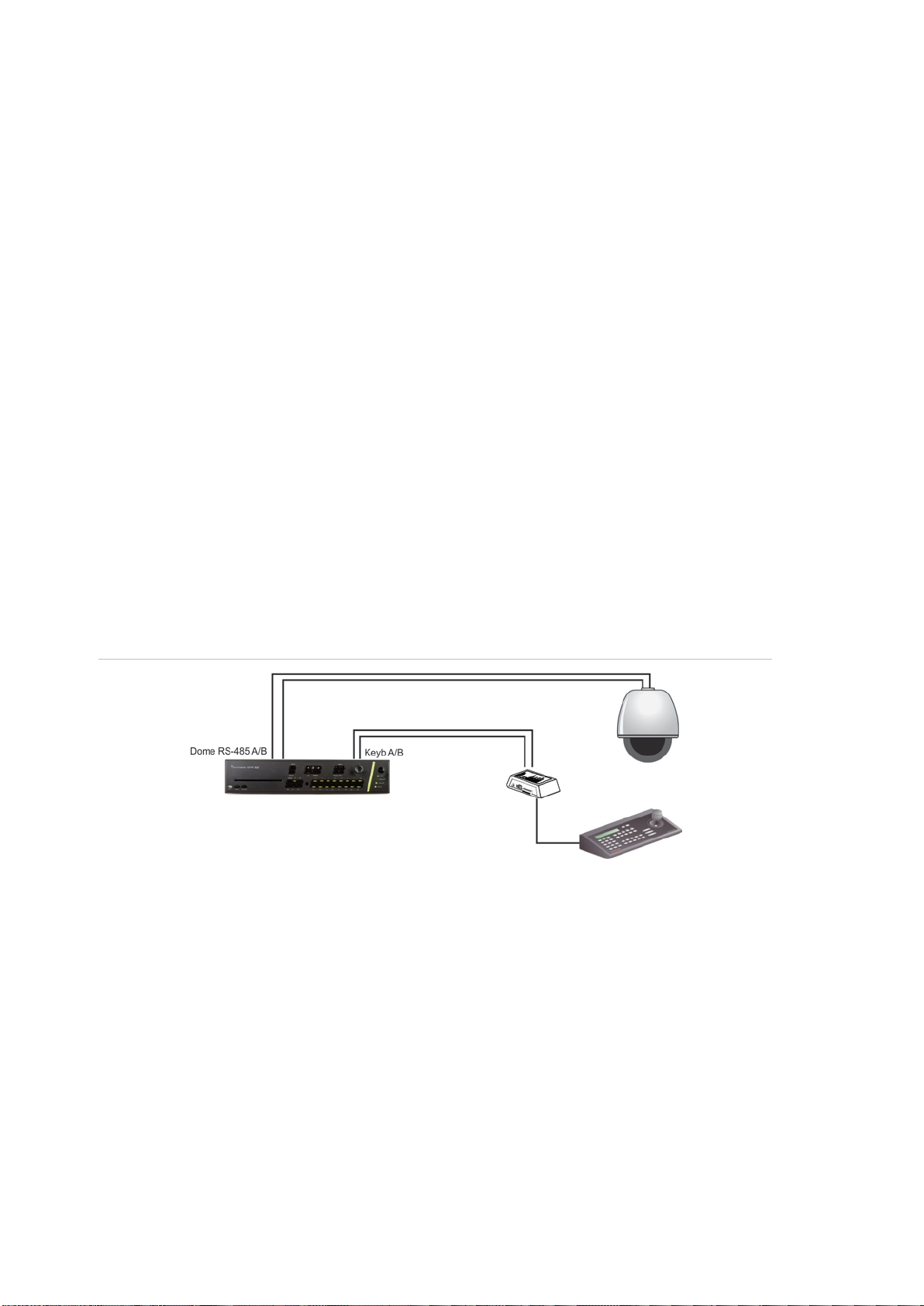
See Figure 4 below for the preferred setup. Any PTZ dome camera can be
controlled as the DVR is doing the PTZ protocol translation. However, this setup
provides only limited dome configuration.
Figure 4: Connecting a KTD-405 keypad to the TVR 42 for control of a PTZ dome camera
over the network
Configuring the PTZ protocols for Interlogix c ame ras
Before the PTZ dome cameras are assembled in their housings, set their
protocol and address DIP switches for the TVR 42. See Table 3 on page 13 for
different Interlogix PTZ dome camera settings.
If you are using PTZ dome cameras from another company, please refer to their
configuration instructions.
12 TruVision DVR 42 User Manual

Camera
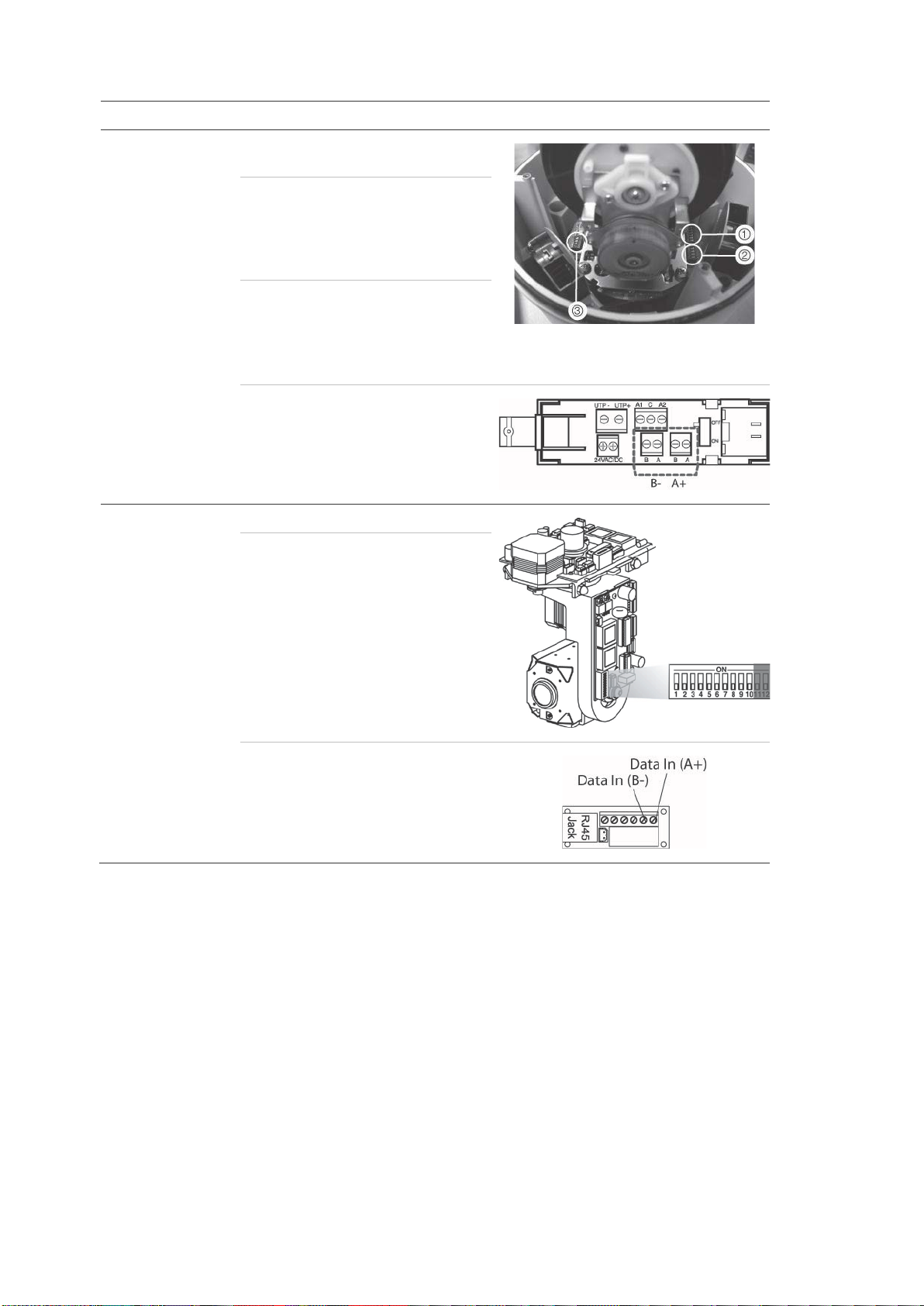
TruVision Mini PTZ
12X: Indoor Dome
485 communication DIP switches
3. Camera ID DIP switches
TruVision Mini PTZ
12X: Outdoor
Dome
485 communication DIP switches
3. Camera ID DIP switches
Table 2: PTZ protocols for Interlogix cameras
Switch setting
Protocol DIP
switches:
RS-485
000000
0000000000
communication DIP
switches:
Camera ID DIP
switches:
Select the
camera ID
DIP switch
address as
required
1. Protocol DIP switches
2. RS-
RS-485 data connector:
Protocol DIP
000000
switches:
RS-485
0000000000
communication DIP
switches:
Camera ID DIP
switches:
Select the
camera ID
DIP switch
address as
required.
RS-485 data connector:
1. Protocol DIP switches
2. RS-
TruVision DVR 42 User Manual 13
Camera
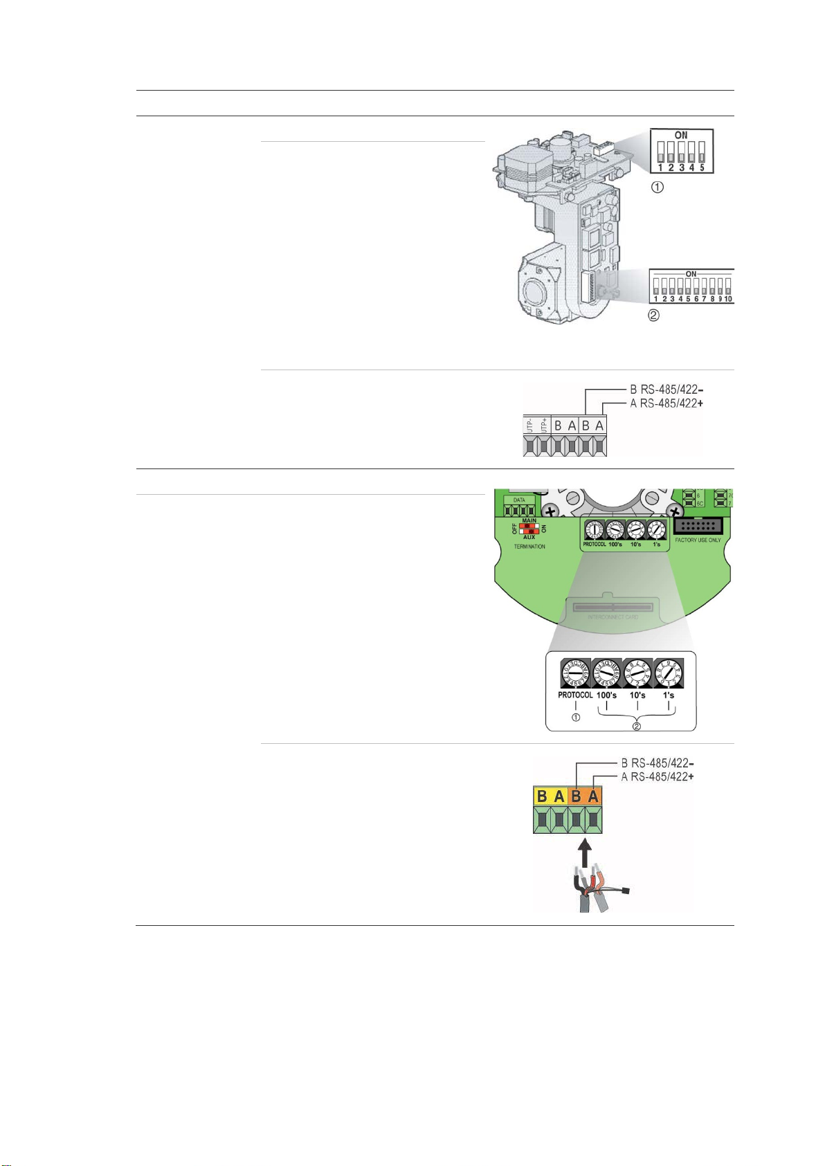
TruVision Dome
16X PTZ
1. Address switches; 2. Baud switches;
3. Protocol switches
CyberDome
Switch setting
Protocol switches: 0111
Address switches: Select the
camera ID
DIP switch
address as
required.
Baud rate: 0000
RS-485 data connector:
Protocol switches: NA
Address switches: Select the
camera ID
DIP switch
address as
required.
RS-485 data connector:
14 TruVision DVR 42 User Manual
Camera
UltraView PTZ
2. Address switches
Legend
Switch setting
Protocol switches: 01000
Address switches: Select the
switch
address as
required.
1. Protocol switches;
RS-485 data connector:
Protocol switches: 1
Address switches: Select the
camera ID
DIP switch
address as
required.
RS-485 data connector:
TruVision DVR 42 User Manual 15
2. I/O box
Wiring the KTD-405 keypad
The KTD-405 keypad uses RS-485 simplex wiring. The signal is transferred by a
single twisted pair line. A shielded STP CAT5 network cable is recommended.
Ground one end of the cable, either the first or last device on the RS-485 line.
The maximum number of devices that can be installed in one bus is 255, with a
maximum cable length of 1200 m. The cable length can be expanded using a
signal distributor.
Both the first and the last device in series should be terminated with 120 Ohm
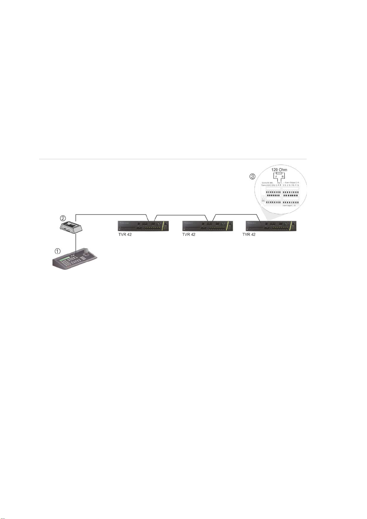
resistance to minimize line reflections. See Figure 5 below.
Figure 5: RS-485 bus serial wiring
1. Keypad (KTD-405 keypad shown)
3. See section “RS-485 ports” on page 9
Use an RS-485 signal distributor for a star wiring configuration. See Figure 6 on
page 17.
16 TruVision DVR 42 User Manual

2. I/O box
4. See section “RS-485 ports” on page 9
2. I/O box
Figure 6: Star wiring with RS-485 signal distributor
Correct:
1. Keypad (KTD-405 keypad shown)
3. RS-485 distributor
Incorrect:
1. Keypad (KTD-405 keypad shown)
3. See section “RS-485 ports” on page 9
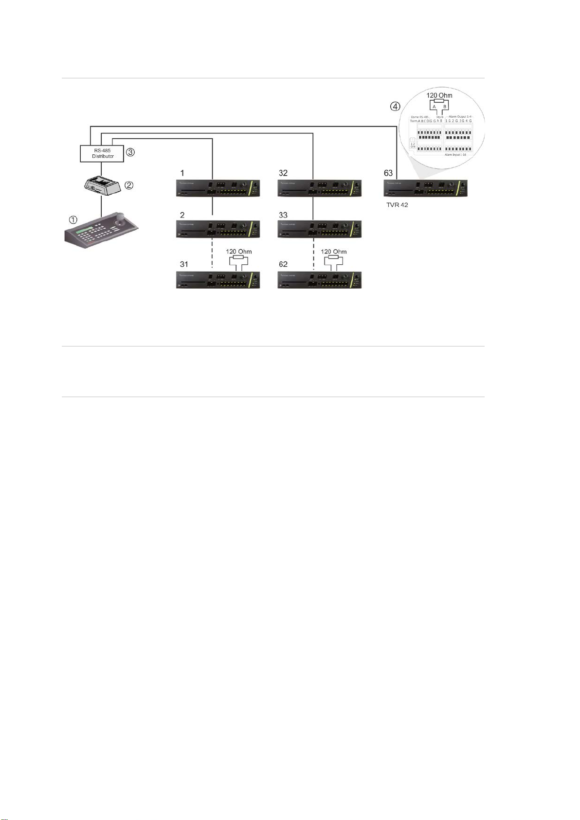
Use an RS-485 signal distributor to increase the maximum number of devices on
the bus as well as the total range. Each distributor output provides another RS485 bus, extending the output an additional 1200 m. Up to 31 TVR 42s can be
connected to each output. See Figure 7 on page 18.
TruVision DVR 42 User Manual 17
2. I/O box
4. See section “RS-485 ports” on page 9
Figure 7: Expanding the system with an RS-485 signal distributor
1. Keypad (KTD-405 keypad shown)
3. RS-485 distributor
Caution: Most signal distributors are unidirectional. This means that the signal
only flows from the input towards the outputs. Consequently it is not possible to
connect several keypads.
See section “RS-485 ports” below to configure the RS-485 port communication
settings.
18 TruVision DVR 42 User Manual

Chapter 3
Getting started
Turning on and off the DVR
Before starting the power up process, connect at least one monitor to the BNC,
HDMI, or VGA outputs. Otherwise, you will not be able to see the user interface
and operate the device. Also connect at least one camera.
The DVR auto-detects the video mode (PAL or NTSC) on startup.
It is equipped with a universal power supply that will auto-sense 110/240 V,
60/50 Hz.
Note: It is recommended that an uninterruptible power supply (UPS) is used in
conjunction with the device.
To turn on the DVR:
Turn on the DVR using the power switch on the back panel. A splash screen
appears on screen.
Once the TVR 42 is powered up, the indicator bar on the front panel will light up
green. All connected cameras are displayed on-screen. The TVR 42
automatically begins recording.
To turn off the DVR:
1. In live view mode, right-click the mouse and click Menu. The main menu
window appears.
2. Select the Power Manager icon.
3. In the Shutdown popup menu, select Shutdown. Click Yes to confirm
shutdown.
To reboot the DVR:
1. In live view mode, right-click the mouse and click Menu. The main menu
window appears.
2. Select the Power Manager icon.
3. In the Shutdown popup menu, select Reboot. Click Yes to confirm shutdown.
TruVision DVR 42 User Manual 19

Using the setup wizard
The TVR 42 has an express installation wizard that lets you easily configure
basic DVR settings when first used. It configures all cameras simultaneously.
The configuration can then be customized as required.
By default the setup wizard will start once the DVR has loaded. It will walk you
through some of the more important settings of your DVR.
Any changes you make to a setup configuration page are saved when you exit
the page and return to the main wizard page.
Note: If you want to set up the DVR with default settings only, click Next in each
window until the end.
To quickly set up the DVR:
1. Connect all the devices required to the back panel of the DVR. See Figure 1
on page 9.
2. Turn on the unit using the power switch on the back panel. After the boot up
window, the DVR displays video images on screen.
3. Select the preferred language for the system from the dropdown list and then
click Next.
4. Enable or disable the option to start the wizard automatically when the DVR is
turned on. Click Next.
5. Administrator conf iguration:
Navigate to the Admin Password edit box and click the edit box with the
mouse, or press Enter on the front panel or remote control, to display the
virtual keyboard. Enter the default admin password, 1234.
Note: You must enter an admin password. To change the Admin password,
check New Admin password and enter the new password and confirm it.
Caution: It is strongly recommended that you change the password of the
administrator. Do not leave 1234 as the default password. Write it down in a
safe place so that you do not forget it.
If you should forget the password to your DVR, contact your supplier with the
serial number of your DVR to obtain a secure code to reset your DVR.
Click Next.
6. Time and date configuration:
Select the desired time zone, date format, system time and system date.
Note: Daylight savings time (DST) cannot be configured from the wizard. See
“Configuring time and date” on page 42 for more information on DST.
20 TruVision DVR 42 User Manual

Note: The system time and date are visible on screen. However, they do not
appear in recordings.
Click Next to move to the next page, or Previous to return to the previous
page.
7. Network configuration:
Configure your network settings such as the NIC type, IP address, subnet
mask and default gateway. Enter the preferred DNS server address as well
as the alternate one to use.
Click Next to move to the next page, or Previous to return to the previous
page.
8. HDD management:
Configure your HDD settings as required.
You can group HDDs and assign cameras to a group. See “Setting up HDD
groups” on page 122 for further information. You can also set up a drive for
redundant recording. See “HDD redundancy” on page 98.
After configuring your HDD settings, click Initialize to initialize the HDD and
Next to move to the next page, or Previous to return to the previous page.
TruVision DVR 42 User Manual 21

9. Recording configuration:
Configure your recording settings as required. The settings apply to all
cameras connected to the DVR. There are two recording configurations:
Auto record settings: The window for “Auto Record Settings” is shown
below.
Advanced record settings: The window for “Advanced Record Settings” is
shown below.
Check the Constant Recording checkbox for the DVR to record continuously
all day. If left unchecked, the DVR will not record.
Check the TL-Hi check box and select its image resolution and fr am e rate.
Check the TL-Lo check box and select its image resolution and frame rate.
To record motion detection events, check Event (Motion) and select the
image resolution and frame rate.
To record alarm events, check Alarm and select the image resolution and
frame rate.
Under Camera name enter the camera name. A soft keyboard will ap pear to
enter the characters.
10. When all the required changes have been entered, a page appears showing
all the settings.
22 TruVision DVR 42 User Manual

Click Finish to exit the Wizard. The TVR 42 is now ready to use.
TruVision DVR 42 User Manual 23

Chapter 4
Operating instructions
Controlling the TVR 42
There are several ways to control the DVR:
• Front panel control
• Mouse control
• IR remote control
• KTD-405 keypad control (see Appendix)
• Web browser control
You can use your preferred control method for any procedure, but in most cases
we describe procedures using mouse terminology. Optional control methods ar e
given only when they differ substantially from mouse control methods.
Using the front panel
The function buttons on the front panel control can be used to operate many, but
not all, of the main functions of the DVR. The LED indicators light up to alert you
of various conditions. The functions available can be limited by setting
passwords. See Figure 8 on page 25 for more information.
24 TruVision DVR 42 User Manual
Item
1.
The recorder supports additional devices such as a USB
2.
3.
4.
5.
6.
7.
Switch between different cameras in live, P T Z cont rol or
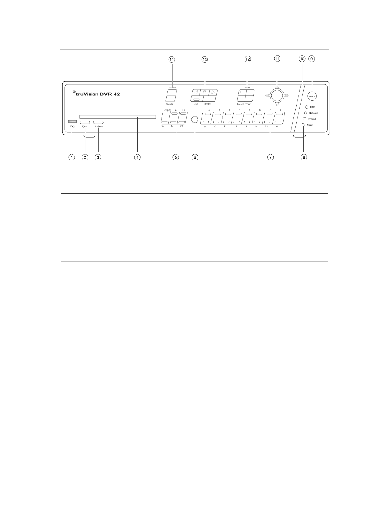
Figure 8: Front panel
The controls on the front panel include:
Name Description
USB port
mouse, CD/DVD burner, and a USB HDD on the f ront
and rear USB ports.
Eject button Ejects CD/DVD disc.
Archive button Press once to enter quick archive mode. Press t wice to
start archiving.
CD/DVD slot Insert a CD or DVD disc.
Display buttons Display: Togg l es t hrough the various multiviews: full,
quad, 1+5, 1+7, 9, and 16.
Sequence: Starts/stops sequencing in live v i ew mode.
A: Selects the main monitor.
B: Selects the spot monitor (in live view).
F1: In all-day playback, click to start and stop video
clipping.
F2: In live view mode, click to display/hide t he time bar.
In all-day playback, click to hide/display the playback
control toolbar.
IR receiver Receiver for IR remote.
Channel buttons
playback modes. Use the soft keyboard to enter
numerals 0 to 9.
TruVision DVR 42 User Manual 25

Item
8.
that the recorder
: A steady red light indicates that there is a sensor
9.
10.
11.
Use to select options in a menu and to control playb ack.
Move the joystick left/right and up/down to
12.
13.
snapshot playback mode, view snapshots in the reverse
Name Description
Status LEDs HDD: A steady green light indicates that the recorder i s
accessing the HDD in read or write mode. A steady red
indicates a HDD failure.
Network: A steady green light indicates that the
recorder is currently connected to a network. No l ight
indicates that it is not connected to a network.
Internal: A steady green light indicates
is recording video or audio. No light means that i t is not
recording. A steady red light means that there has been
an internal health failure.
Alarm
Alarm In or other alarm such as motion detection or
tampering. A steady green light means there i s no
alarm.
Alarm button Use to manually acknowledge an alarm. In live view
mode, use it to call the alarm recipient.
Alarm indicator bar Blinking red indicates that there is an alarm.
Joystick
Press for Enter. The LED arrows are lit when the jog is
active.
Live view mode: Press Enter to enter/exit PTZ mode.
Menu mode:
position cursor in the menu window. Press for Enter.
Playback mode: Move the joystick left/right to slow
down or speed up playback. Move it up/down to jump
forwards or backwards by 30 seconds. Press Enter to
stop/start playback.
PTZ mode:
Move the joystick to control the movement of the P TZ
dome camera. Move the joystick left/right to slow down
or speed up PTZ. Move it up/down to jump forwards or
backwards by 30 seconds.
PTZ buttons Zoom: Use + and – for digital zoom.
Playback buttons Reverse: In live view mode, press to jump back to
26 TruVision DVR 42 User Manual
Preset: Call up preprogrammed preset positio ns.
Tour: Call up preprogrammed shadow tours.
the oldest available video and start play back. I n
playback mode, press to play back video in reverse. In
direction.
Pause: In live view mode, freeze the last image of
the live video. In playback mode, pause playba ck.
Forward: In live view mode, press to start all-day
playback of the currently selected camera. If you are in
multiview format, only the camera shown in the top-left
corner of the multiview is played back
Live: Switch to live view mode.
Replay: Replay the current file in playback Starts at the
beginning of the file.

Item
14
Item
Left button
Right button
Scroll
Name Description
. Menu and Search buttons Menu: Enter/exit the main menu.
Search: In live view mode, enter the advanc ed search
menu.
Using the mouse
The USB mouse provided with the DVR can be used to operate all the functions
of the DVR, unlike the front panel which has limited functionality. The USB
mouse lets you navigate and make changes to settings in the user interface.
Connect the mouse to the DVR by plugging the mouse USB connector into the
USB port on the back or front panel. The mouse is immediately operational and
the pointer should appear.
Note: Use a USB 1.1 or higher mouse.
Move the pointer to a command, option, or button on a window. Click the left
mouse button to enter or confirm a selection.
You can purchase a spare mouse by ordering part number TVR-MOUSE-1.
See Table 4 below for a description of the mouse buttons.
Table 3: Mouse buttons
Description
Single-click L ive view: Select a camera to display the quick
access toolbar (see “Accessing frequently used
commands” on page 37).
Menu: Select a component of a menu, such as a
button or an input field. This is similar to pressing the
Enter button on the remote/front panel contr ol s.
Double-click Live view: Switch between single screen and multi-
screen mode in live/ playback mode.
Click and drag L ive view: Drag channel/time bar.
PTZ control: Adjust pan, tilt and zoom.
Tamperproof, privacy masking and motion
detection functions: Select the target area.
Digital zoom-in: Drag and select target area.
Single-click Live view: Display menu.
Menu: Exit the current menu and return to higher
level.
-wheel Scroll up Live view: Return to the previous window.
Menu: Move the selection to the previous item.
Scroll down Live view: Move to the next window.
Menu: Move the selection to the next item.
TruVision DVR 42 User Manual 27
Item
Description
1
Acknowledge an alarm.
2
Enable/disable the IR remote control to control the
3
Select a camera, and enter a number in a menu opt ion.
4
Switch
5
Switch
6
Return to
Using the IR remote control
The TVR 42 is supplied with an infra red (IR) remote control unit. Like the mouse,
it can be used to operate all of the main functions of the TVR 42.
The IR remote control can be programmed with a unique device ID address so
that the controller will only be able to communicate with DVRs with that address.
No programming is necessary if using a single TVR 42.
The device ID address only applies when using a remote control and not when
using a keypad.
You can purchase a remote control by ordering part number TVR-REMOTE-1.
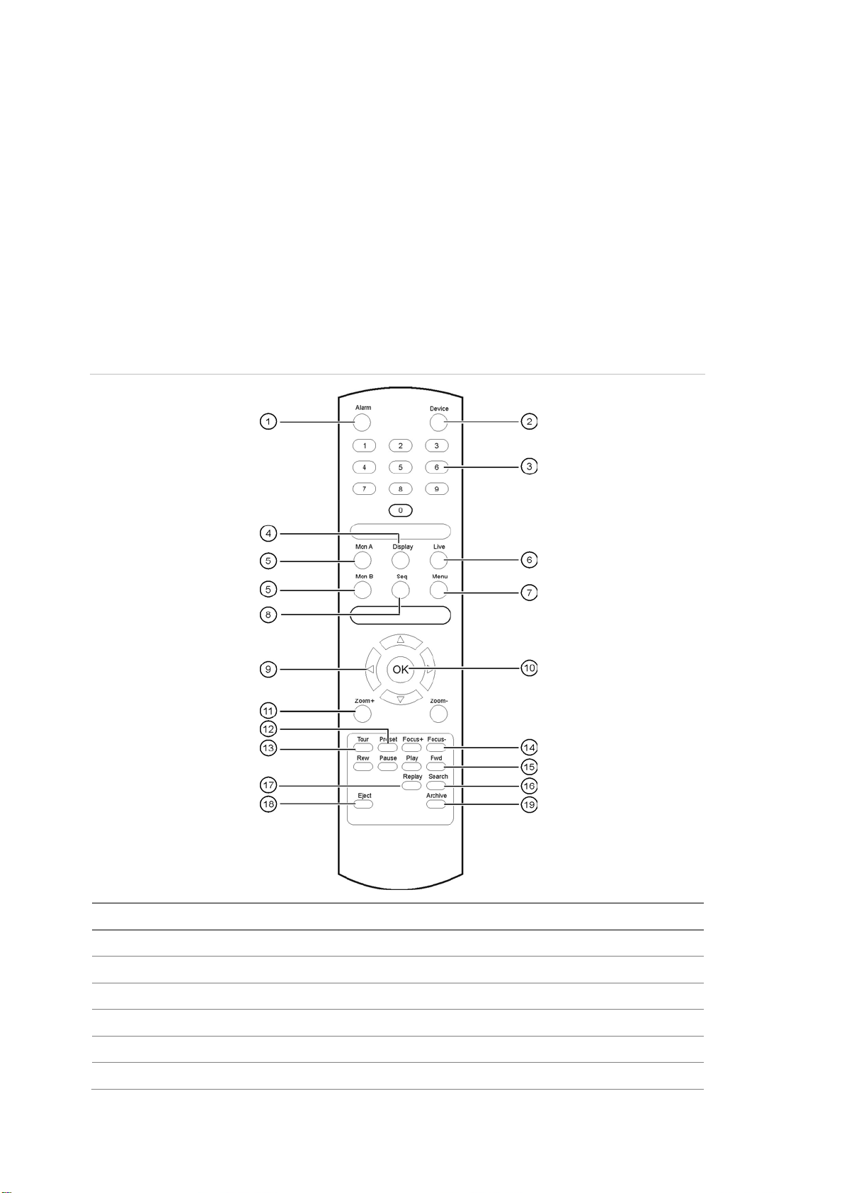
Figure 9: IR remote control
. Alarm
. Device
. Numeric buttons
. Display
. Mon A and Mon B
. Live
28 TruVision DVR 42 User Manual
between the different multiviews.
between monitors A and B.
live view mode.
TVR 42.
 Loading...