

Page 1
Sentrol
DV1201A & DV1221A
Seismic Detectors Installation Manual
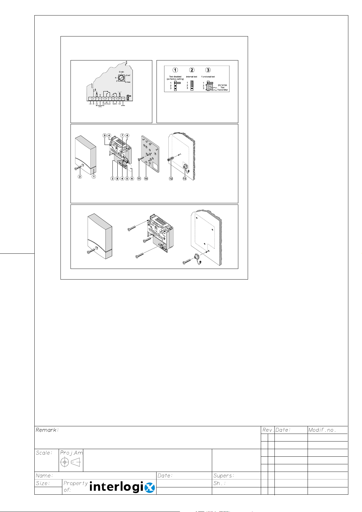
Figure 1: Wiring diagram
1/2. 12 Vdc 7. Common (C)
3. LED indication 8/9. Tamper
4. Integrator level 10. Test control
5. Normaly Closed (NC) 11. Spare
6. Normaly Open (NO)
Figure 3: General characteristics of the DV1201A / DV1221A
Using the mounting plate DV1202A as a template
A. Holes for DV1201A / DV1221A
B. Hole for expansion plug or recess mounting box
C. Template and mounting holes for test transmitter DV1215A
D. Holes for accessories.
Figure 4: Mounting the detector directly on a metal surface without using a mounting plate
Figure 2: Two ways to test the seismic detectors
Test disabled (ex-factory setting)
Internal test of detector’s electronics =
Position jumper between 1 and 2 .
Function test of the detector and its physical contact
with the protected object = Position connector from
test transmitter DV1215A between 2 and 3.
Connecting terminal 10 to 0 V activates both tests.
1. Cover
2. Cover screw
3. Base plate
4. Mounting holes
5. Clamp
6. Area for mounting the
DV1215A test transmitter
7. Potentiometer for adjusting
the detector’s sensitivity
8. Connection block
9. Anti-tamper micro-switch
10. Mounting plate DV1202A
11. Fixing bolt
12. Expander bolt
13. Test transmitter DV1215A
- 1 -
Form: Letter (bookshape)
Formaat: Letter (boekvorm)
White paper: 70gr/m² progresso; overprint black. If P.O.D.: use 80gr/m².
Wit papier: 70gr/m² progresso; opdruk zwart. Wanneer P.O.D.: gebruik 80gr/m².
1 A 24-04-'02 10423-10424
G. Manders
A4
Manual DV1201A / DV1221A
24-04-'02
5620
14 999-
110-01
Page 2
Sentrol
DV1201A & DV1221A
Seismic Detectors Installation Manual
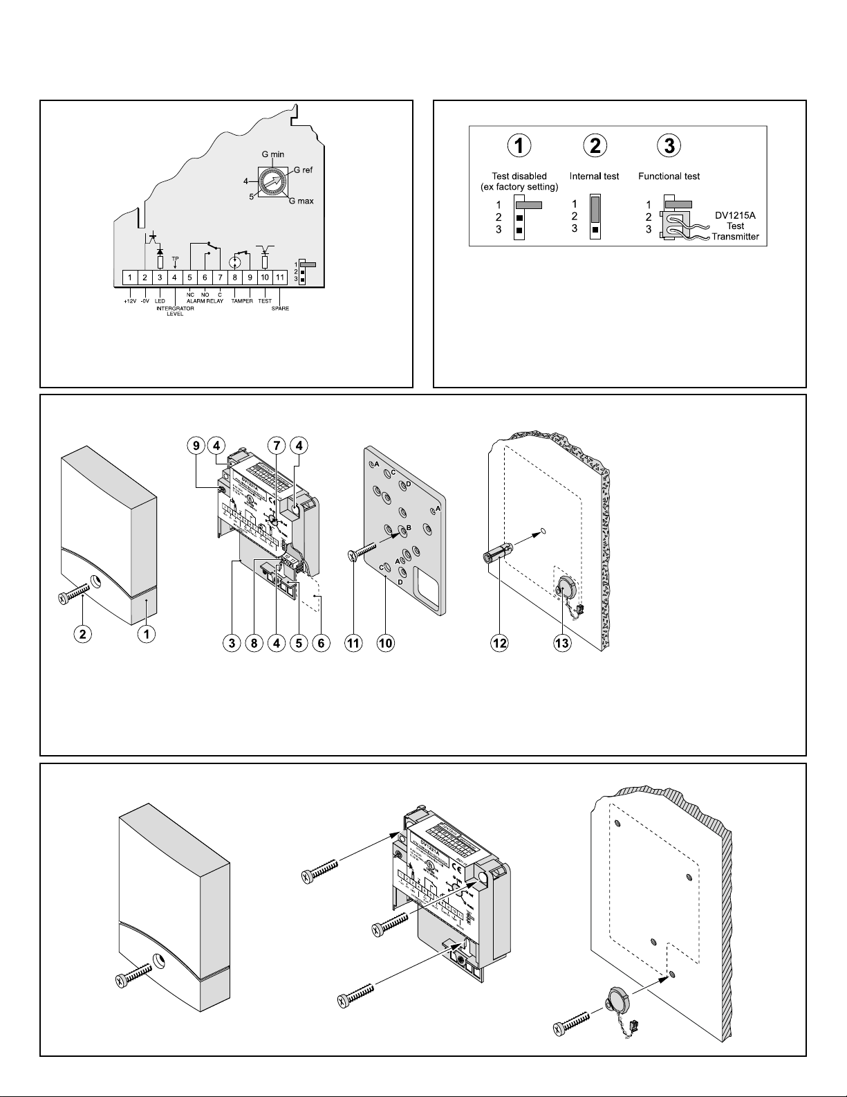
Figure 1: Wiring diagram
1/2. 12 VDC 7. Common (C)
3. LED indication 8/9. Tamper
4. Integrator level 10. Test control
5. Normaly Closed (NC) 11. Spare
6. Normaly Open (NO)
Figure 3: General characteristics of the DV1201A / DV1221A
Figure 2: Two ways to test the seismic detectors
! Test disabled (ex-factory setting)
" Internal test of detector’s electronics =
Position jumper between 1 and 2 .
# Function test of the detector and its physical contact
with the protected object = Position connector from
test transmitter DV1215A between 2 and 3.
$
Connecting terminal 10 to 0 V activates both tests.
1. Cover
2. Cover screw
3. Base plate
4. Mounting holes
5. Clamp
6. Area for mounting the
DV1215A test transmitter
7. Potentiometer for adjusting
the detector’s sensitivity
8. Connection block
9. Anti-tamper micro-switch
10. Mounting plate DV1202A
11. Fixing bolt
12. Expander bolt
13. Test transmitter DV1215A
Using the mounting plate DV1202A as a template
A. Holes for DV1201A / DV1221A
B. Hole for expansion plug or recess mounting box
C. Template and mounting holes for test transmitter DV1215A
D. Holes for accessories.
Figure 4: Mounting the detector directly on a metal surface without using a mounting plate
- 1 -
Page 3

Figure 5: Mounting on concrete
Always use a DV1202A mounting plate. The expansion plug must
penetrate at least 50 mm into the concrete. Please follow the steps
shown in Figure 6 if you are installing the test transmitter DV1215A.
$
For the equipment to conform to CEI standard 79-2, the
DV1215A test transmitter must be installed.
Figure 6: Control and function test
Using a voltmeter, check the background signal level in the detector
to prevent nuisance alarms. Set the sensitivity to Gmax during the
test.
DV1201A DV1221A Measure
0.7 V 0 V None
1.4 V 2 V Reduce range/remove source
Detection range (in foot):
Material Thermal
Concrete 13.12 45.93 45.93
Steel 1/G
Brick 9.84 26.25 26.25
Concrete 9.84 29.53 29.53
Steel 2/G
Brick 3.28 19.69 19.69
Concrete 6.56 19.69 19.69
Steel 3/G
Brick - 13.12 13.12
Concrete 3.28 16.40 16.40
Steel 4 3.28 16.40 16.40
Brick - 9.84 9.84
Concrete - 13.12 13.12
Steel 5 - 13.12 13.12
Brick - 6.56 6.56
Sensitivity
setting
max
ref
min
lance
26.25 45.93 45.93
13.12 29.53 29.53
6.56 19.69 19.69
Diamond
disk
Drilling
$
Try to remove the source of ambient noise instead of
reducing the range.
Functional testing with hand tester DV1230 ! and mechanical
tool
":
DV1201A DV1221A
Alarm in 30 sec. Alarm in 45 sec.
Alarm after 5 blows NA
Technical specifications:
Input power: 9-15 VDC
2 V max. ripple pp
Current consumption: Nom. 8.6 mA
Alarm output: Form C solid state relay, max. series
resistance 35 Ohm
Alarm indication: LED-ind. output 3
Sensitivity: 5 steps of 6 dB each
Range: See Table “Detection range”
Sabotage protection: Temp. 183.2 °F
drill shield,
opening/pry-off contact,
Low voltage alarm: 7.5 V
Temperature limits: -4 °F to + 131 °F
Dimensions: 3.93 x 3.15 x 1.30 inches
Colour: Grey, RAL 7035
Weight: 0.86 lb
- 2 -
Page 4

Figure 7: Wiring the DV1201A/DV1221A into Most Security Systems
Figure 8: Connecting the DV1201A to a Four-wire Circuit
Type Control in an UL Complete Mercantile Safe System
Figure 10: Wire Diagram DV1208A
Figure 9: Connecting the DV1201A to a Two-wire Balanced
Loop Type Control in an UL Complete Mercantile Safe
System
- 3 -
Page 5

Figure 11
- 4 -© Sentrol is an Interlogix company. 2002. All rights reserved. 5620-1A
 Loading...