

Page 1
1.0 INTRODUCTION
The Advisor X Structural Vibration Detection System is a seismic detection system designed to detect attempts to break into
vaults, safes, night deposit safes, automatic cash dispenser
units and other reinforced physical areas such as data storage
and filing cabinets.
To achieve this high level of accuracy, the system analyzes
three major parameters-signal strength, signal frequencies, and
signal duration-before triggering an alarm. These parameters
differentiate real break-in attempts from nuisance signals. In
general, the signal characteristics of a true break-in
attempt include:
• Explosives: generate a signal with a very high amplitude and
a short duration.
• Mechanical Destruction (hammer and chisel): generates
signals with a rather high amplitude and a short intermittent signal duration.
• Rotating Devices: generate signals with a moderate to high
amplitude and a long signal duration.
• Thermal Devices: generate signals with low amplitude and a
long signal duration.
2.0 PLANNING INSTALLATION
2.1 What to Avoid
Although the Advisor X System is designed to provide a high
level of immunity against nuisance alarms, some precautions
should be considered when planning an installation. Do not
install detectors close to electric motors, transformers, fans, air
conditioners or other electrical devices that create mechanical
vibrations in the protected structure. Avoid mechanical contact
between electrical devices and the surface of the protected
structure, or dampen the vibrations by using rubber-like insulating materials.
Water Piping
The flow of water through piping in mechanical contact with the
protected structure emits a strong signal in the structure itself
and may cause nuisance alarms.
Ultrasonic Detectors
Ultrasonic detectors may emit a signal that is within the frequency range of the Advisor X detectors. Avoid placing ultrasonic detectors closer than six feet to the protected surface.
Bells
Bells may generate overtones in the frequency range of the
Advisor X detectors. Place a piece of tape on the bell to suppress the overtones, drill a hole in the gong, or relocate the bell
to remove the hazard.
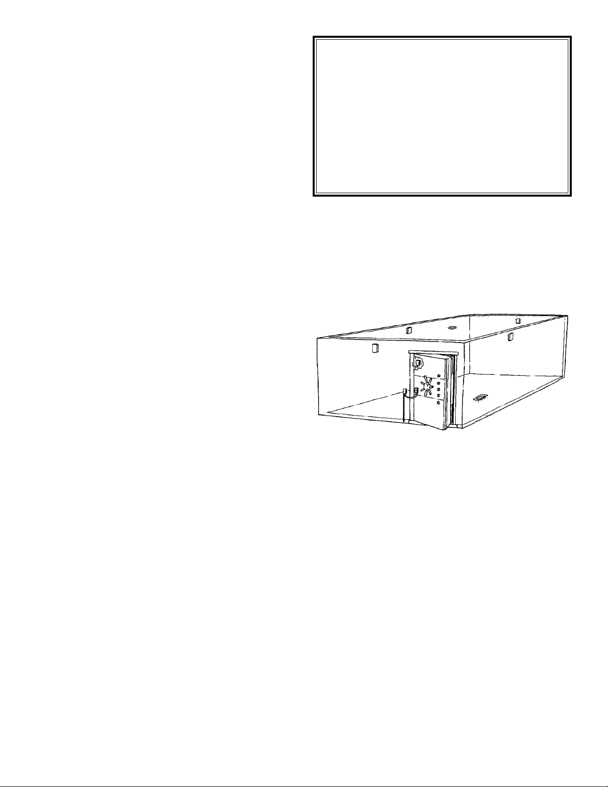
2.2 Planning Vault Protection
Generally, it is advisable to place one detector on each
wall, floor, and ceiling inside the vault and one detector on
or inside the vault door. See the following section on detec-
tion range and sensitivity test. The detectors can be mounted
with the Mounting Plate (supplied), the DV1212 Steel Surface
Mounting Plate recess mounted with the DV1203 Recessed
Mounting Plate. Mount the detectors at a height of at least six
feet (1.8m) to avoid interference from document cabinets and
deposit boxes.
FIGURE 1 - DETECTOR PLACEMENT
Special consideration must be given to installations in which a
UL certificate (UL 681) is to be awarded. This includes, but is
not limited to, power supply requirements, system test needs,
and protection of interconnection cable.
Since the vault door is isolated from the walls by its hinges,
have one detector inside the vault door. Newer vault doors normally have cable channels inside the hinges to provide easy
connection of the sensor.
An optional means of protecting the vault doorway is to mount
a detector on the outside of the door. This provides protection
against torch-cutting and thermic bar attack at an early stage,
since the vault door acts as a membrane and detects the signal
even before the surface attack has started. The detector can be
mounted directly on the surface or with a DV1202 or DV1203
mounting plate. See mounting instructions, Section 3.0.
The DV1219 Armed Cable Kit and the DV1228 Metal Junction
Box allows cabling from the door to the door frame on the hinge
side with armored cable. Be careful when drilling into the vault
door. Sometimes there is a printed circuit board drill protection
behind the outer steel plate. (Consult the vault door manu-
facturer for details.)
1
Sentrol, Inc
DV1200 Series, Advisor X
Structural Vibration Detection System
Installation Instructions
Models DV1201, DV1221
Page 2

2.3 The Vault Sensitivity Test for Irregularities
If the surface of the vault or safe shows cracks, gaps or has
other irregularities, perform a test to determine if the protection
range of each sensor is affected. Additional sensors may be
required for optimal coverage. This test is not necessary when
sensors are mounted on a steel surface. For concrete, block
and brick construction, perform the following test, using an electric drill and a 1/4” (6mm) carbide-tipped bit.
1. Locate any irregularity in the construction. The mortar
between bricks and blocks should be considered as
irregularities.
2. Install the sensor at one side of the suspected irregularity.
See mounting instructions.
3. Wire the sensor to power and to the alarm circuit.
4. Set the sensor sensitivity to MAX.
5. Drill into the wall at a point equal to the protection radius (R)
depending on the construct type as described in the table
below. Check for an alarm.
6. If an alarm does not occur, assume that the irregularity
inhibits the protection range of the detector. Redrill closer to
the sensor until an alarm occurs and identify the proper protection radius for that particular site.
7. Take all irregularities into account when spacing sensors.
Additional sensors may be required. Note: The separation
between the vault door and the frame will require an
additional detector on the door to counter a possible
weakness at this point.
2
TABLE 1 - ESTIMATING DETECTOR RANGE ON A VAULT
Protective Radius
Methods of Attack
Sensitivity Thermic Diamond
Material Setting Lance Disk Drilling
Concrete K-350 1 13ft.,2in. (4m) 45ft.,11in. (14m) 45ft.,11in. (14m)
Steel 26ft.,3in. (8m) 45ft.,11in. (14m) 45ft.,11in. (14m)
Brick G Max 9ft.,10in. (3m) 26ft.,3in. (8m) 26ft.,3in. (8m)
Concrete K-350 2 9ft.,10in. (3m) 29ft.,7in. (9m) 29ft.,7in. (9m)
Steel 13ft.,2in. (4m) 29ft.,7in. (9m) 29ft.,7in. (9m)
Brick G Ref 3ft.,4in. (1m) 19ft.,8in. (6m) 19ft.,8in. (6m)
Concrete K-350 3 6ft.,7in. (2m) 19ft.,8in. (6m) 19ft.,8in. (6m)
Steel 6ft.,7in. (2m) 19ft.,8in. (6m) 19ft.,8in. (6m)
Brick G Min - 13ft.,2in. (4m) 13ft.,2in. (4m)
Concrete K-350 4 3ft.,4in. (1m) 16ft.,5in. (5m) 16ft.,5in. (5m)
Steel 3ft.,4in. (1m) 16ft.,5in. (5m) 16ft.,5in. (5m)
Brick - 9ft.,10in. (3m) 9ft.,10in. (3m)
Concrete K-350 5 - 13ft.,2in. (4m) 13ft.,2in. (4m)
Steel - 13ft.,2in. (4m) 13ft.,2in. (4m)
Brick - 6ft.,7in. (2m) 6ft.,7in. (2m)
2.4 Planning Guidelines
Dos
• Do prepare a vault layout plan showing vault dimensions and
locations of all equipment to be installed.
• Do check that vault is constructed of monolithic concrete or
concrete with steel liner; if constructed of concrete block or
brick, masonry must be bonded with Portland cement.
• Do check that sensors are mounted directly to masonry or
steel surface and that approved mounting hardware is used.
• Do install at least one sensor on each wall, as well as on the
floor and ceiling.
• Do protect vault door with sensor mounted as close as possible to side of door, embedding it in door frame.
• Do perform drill tests, whenever possible, on the outside of the
vault.
• Do apply silicone sealant around all openings of sensor cover,
screw heads, and cable port) after surface-mounting sensor
on floor.
Don’ts
• Don’t assume that covered concrete walls are free of cracks,
loose mortar or other irregularities.
• Don’t install sensors permanently before determining sensitivity settings and ambient noise levels.
• Don’t install sensors on cinder block or other unapproved
masonry surface.
• Don’t install ultrasonic sensors inside the vault.
Page 3
• Don’t install sensors close to bells, buzzers, or telephones
unless gong(s) or hammer(s) can be taped to deaden sounds.
• Don’t mount sensors on rough surfaces. Smooth all surfaces.
• Don’t allow test signal transmitter to make contact with mounting plate or sensor on masonry installation.
• Don’t use rigid conduit inside vault except where specified,
e.g. run wiring to door contacts and heat detectors in conduit.
• Don’t install sensors behind safe deposit boxes unless sensors are made accessible for service.
2.5 Requirements When Using One Sensor
(DV1201 or DV1221)
All-steel safes with 1/4” walls*
Safes must be a minimum of 1/4” steel on the body and
1/2” on the door. For this type of safe construction, the overall
size of the safe must not be larger than 12 cubic feet or have:
• The height plus the width not greater than 55 inches, nor
• The height plus the depth not greater than 55 inches, nor
• The width plus the depth not greater than 55 inches.
The sensor can be mounted in or on the safe in close proximity to the door hinges or on the door itself. The sensitivity settings (Refer to Tables 2 and 3) must be adjusted so that adequate detection with the lowest setting is obtained. Use of the
Mounting Plate is optional. (Refer to Section 3.0 for additional
information).
All-steel safes with 1” walls*
Safes must have a minimum of 1” of steel on the body and the
door. The overall size must not exceed 52 cubic feet or
• The height plus the width not greater than 90 inches, nor
• The height plus the depth not greater than 90 inches, nor
• The width plus the depth not greater than 90 inches.
The DV1201 and DV1221 sensors can be mounted on the safe
door or on the body in close proximity to the hinges or inside the
safe. The sensitivity settings must be adjusted to obtain adequate detection with the lowest possible setting. Use of the
Mounting Plate is optional.
* Control panel must be within visual or audible range
for testing.
A concrete-clad safe
The same dimensional rule of thumb applies as for an all-steel
safe with 1” walls. However, if the previous check of safe construction revealed cracks, seams, or other irregularities in the
concrete shell, always assume that two sensors are required for
the safe housing regardless of its size.
FIGURE 2 - STRUCTURAL VIBRATION DETECTOR
Removing the cover screws and cover from the base plate (2)
provides access to the connection terminals (10) and the sensitivity adjustment control (9).
Inside the unit are located:
• main mounting holes (4) (5)
• test transmitter areas (8) (7)
• strain relief (6)
• tamper switch (11)
3.0 INSTALLATION INSTRUCTIONS
3.1 General Instructions for DV1201/DV1221
Structural Vibration Detector
The DV1201/DV1221 Structural Vibration Detectors consist of
cast aluminum housings, with dimensions of 3.1in. x 3.9in. x
1.2in. (8 x 10 x 3cm), and weigh 9 ounces (250gr) each.
To mount the DV1201 and DV1221 on any surface, the following tools are recommended:
• Mounting plate (also used as drilling template) supplied with
each DV1201/DV1221.
• Power drill with hammer
facility.
• Felt pen.
• #36 high speed steel
drill, diam. (for 6-32 tap).
• #29 high speed steel
drill, diam. (for 8-32 tap).
• High speed steel drill,
diam. 7/16”.
• Concrete drill, diam. 1/2”
(for expansion plug).
• Tap for 6-32 screw.
• Tap for 8-32 screw.
• Cutting oil to cool drill bit
and tap when steel
mounting is required.
3
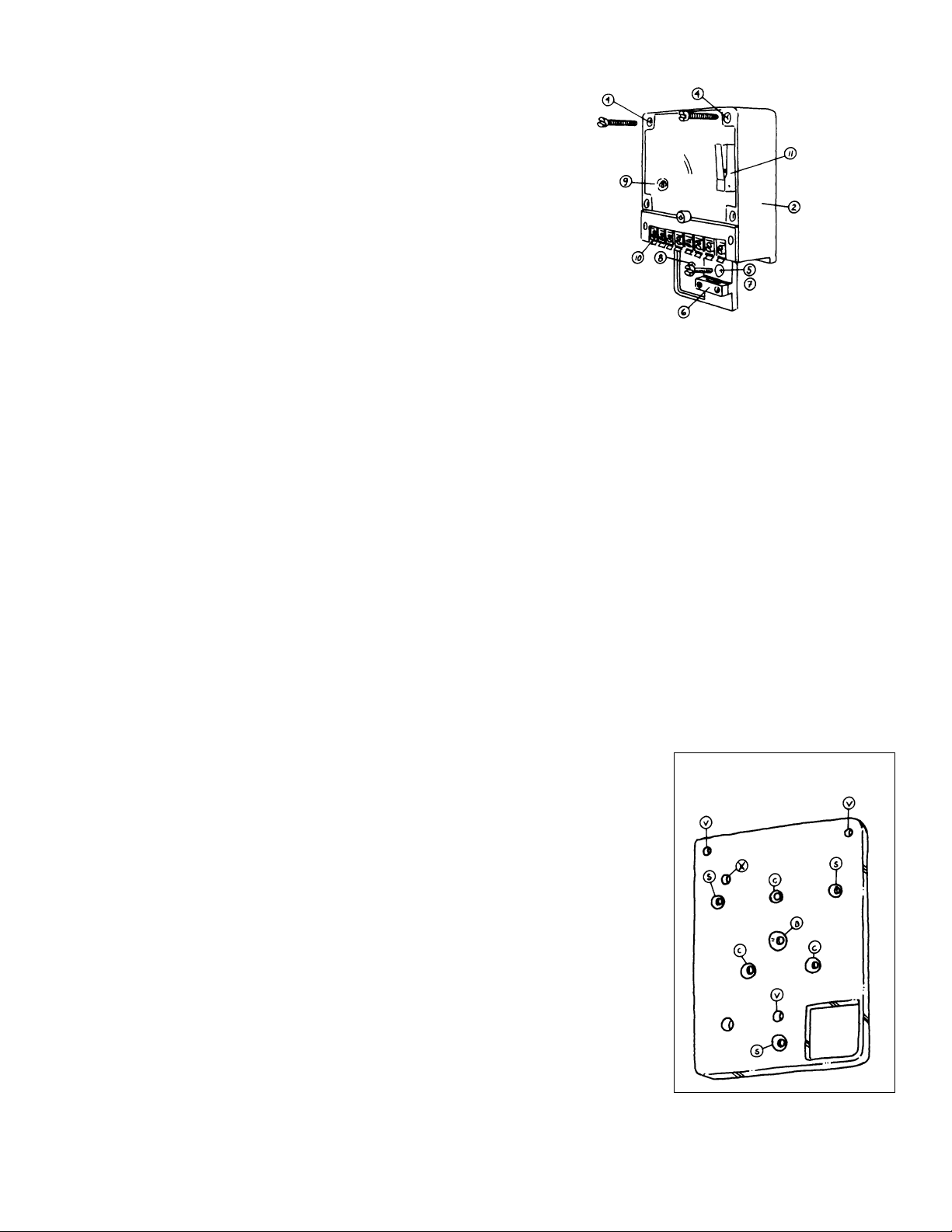
FIGURE 3 -
MOUNTING PLATE
Page 4

FIGURE 4 - MOUNTING DETECTOR
ON A STEEL SURFACE
3.2 Instructions for Mounting Plate
The mounting plate can be used for mounting the DV1201 and
DV1221 onto specific surfaces such as steel and concrete (see
Sections 3.4 and 3.5). The mounting plate also provides an
adaptation hole layout for use in replacing the Securitas SSD70
and the Cerberus GM31,35 GM550 or Arrowhead 3810 detectors (see figure 3).
V = mounting holes for DV1201/DV1221 (threaded holes)
S = mounting holes for DV1201/DV1221 (when replacing
Securitas SSD70)
C = mounting hole for DV1201/DV1221 (when replacing
Cerberus GM31,35 GM550 or Arrowhead 3810)
X = DV1215 drilling pattern on concrete
B = mounting hole for expansion plug
3.3 Direct Mounting the DV1201/DV1221
on a Steel Surface
In certain cases, it is advisable to mount the detector directly
onto a steel surface using
the bolts provided and
threaded holes (made by the
installer).
Mounting instructions for
direct mounting on steel.
1. Define the exact location
of the DV1201/DV1221
when mounted. Hold the
mounting plate in position
on the steel surface.
2. Using the felt pen and
the mounting plate as a
template, mark the
location of the three
threaded holes (see
holes marked “V” in
figure 9).
3. Drill three holes, using
a #29 drill, at least
7/16” deep (see drawing) in the three positions marked.
4. After drilling the holes, tap them with a 8-32 tap, using a little
cutting oil to lubricate the tap. After tapping the holes, use a
7/16” diam. drill to smooth the surface around the hole and to
remove burrs.
5. Mount the detector to the steel surface using the three 8-32
screws provided (see figure 10).
6. If a DV1215 Test Transmitter is used, it can be mounted in
the lower right corner of the detector.
3.4 Indirect Mounting of DV1201/DV1221
on a Steel Surface
In some cases, indirect mounting of the DV1201/DV1221 detectors may be advisable:
• Use the mounting plate when replacing Securitas SSD70,
Cerberus GM31,35 GM550 or Arrowhead 3810.
• Use the DV1212 Welded Mounting Plate if drilling on the pro-
tected surface is impractical or impossible.
3.5 Mounting the DV1201/DV1221 on Concrete
Surface mounting with the mounting plate.
In order to mount the DV1201/DV1221 on concrete, a mounting
plate is always required. Follow the instructions below.
FIGURE 5 - MOUNTING THE DETECTOR
ON CONCRETE
1. Define the exact location of the DV1201/DV1221 and hold
the mounting plate to the wall.
2. Using the felt pen, mark the location of the hole for the
expansion plug on the wall (see drawing).
3. Drill a hole using a 1/2” diam. drill on the spot marked. Be
sure the expansion plug is set flush with or below the surface of the wall.
4
Page 5

4. Insert the expansion plug into the hole just drilled and make
sure that the top end of the plug does not protrude from the
wall. Align the mounting plate over the hole and use a bolt
to secure the mounting plate to the wall. If no test transmitter is used, go to step #10.
5. Before tightening the bolt, twist the mounting plate to position the DV1215 drill pattern hole (see drawing in Section
3.2) where the cable is to be routed (in most cases, at the
bottom). Check for proper horizontal/ vertical alignment of
the DV1201/DV1221.
6. Mark the DV1215 mounting hole using the felt pen. Position
the mounting plate so that the marked spot is over the
DV1215 mounting hole (see drawing in Section 3.2).
7. Drill a hole using a 1/2” diam. drill on the spot marked. Be
sure the expansion plug is flush with or below the surface
of the wall.
8. Insert the DV1215 expansion plug into the hole you have
just drilled, ensuring that the top end of the plug does not
protrude from the wall. Place the DV1215 test transmitter
over the hole and secure using the bolt provided with the
expansion plug.
9. Ensuring that the DV1215 does not touch the mounting
plate, tighten the bolt. To provide proper seating of the
plug, hit the bolt’s head (carefully avoiding the DV1215) a
few times with a hammer and tighten the bolt once more.
NOTE: At the first service visit after the installation, tighten
all bolts once more to compensate for inevitable material
expansion in both wall and plug.
10. After completion of the mounting of the mounting plate on
concrete, install the DV1201/DV1221 detector according to
the description in 3.3.
TABLE 2 - RECOMMENDED SENSITIVITY SETTINGS FOR
A SAFE WITH ONE DV1201 OR DV1221 DETECTOR
Planning the Protection of an Automatic Cash Dispensing
Unit (ATM) and a Night Depository Box
For both units, use the DV1221 to filter out
noise generated by normal operation of the
units. The DV1221 can be mounted directly
on the surface of the structure.
• Automatic Cash Dispensing Unit -
Protection is planned exactly as for a safe.
Note: The DV1221 is not designed for use
on concrete. If the ATM has a concrete
body, a DV1201 can be mounted on the
outside surface or a DV1221 can be
mounted on the inside metal surface.
• Night Safe Deposit Box - Protection is
planned exactly as for a safe. Insulate
the chute and the landing place with rubber insulating material to muffle the
noise created by the cash boxes as they
are deposited.
TABLE 3 - RECOMMENDED SENSITIVITY SETTINGS ON A
CASH DISPENSING UNIT (ATM) AND NIGHT DEPOSITORY
WITH ONE DV1221 DETECTOR
4.0 CABLE REQUIREMENTS
TABLE 4 - ADVISOR X SYSTEM CABLE
REQUIREMENTS
4.1 WS300 Cable Preparation Instructions
The Aritech WS300 High Security Cable is specially designed
to provide electrically protected cabling in a UL Complete
Mercantile Safe System. The cable consists of double circuit
shields that enclose all conductors. When wired per the Wiring
Diagrams in Sections 4.0 and 7.0, the WS300 Cable complies
with the description of electrically protected cable in UL 681.
The two aluminum shields that wrap the eight-conductor cable
are isolated from each other. Each shield is electrically conductive to a drain wire (stranded cable, no insulation). In the
preparation of the cable for connection to the DV1201/DV1221
detector and at the control panel, the shields and corresponding drain wires must be kept isolated. A special cable preparation procedure is described below.
5
Thickness Maximum Method of Attack
of Steel Cubic Ft.
Torch Drilling Mechanical
Over 1/4” but 12 Cu ft:
under 1”
DV1201 3 3 3
DV1221 2 2 2
Over 1” 52 Cu ft:
DV1201 3 3 3
DV1221 1 1 1
Note: These settings are only guidelines. All final settings are to be made
following the steps in Section 5.0.
DV1221
DV1221
Note: These settings are only guidelines. All final settings are to be made following the steps in Section 5.0.
Thickness Maximum Method of Attack
of Steel Cubic Ft.
Torch Drilling Mechanical
Over 1/4” but 12 Cu ft:
under 1”
DV1221 2 2 2
Over 1” 52 Cu ft:
DV1221 1 1 1
Number of
Conductors
Multi Sensor System
with Individ. Indication
Feature Stand-alone DV1208
Power 2 2
Alarm form C 2-4 2-4
Tamper 2 2
Test in 1 1
Test out (LED) - 1
separate
home run
Page 6

FIGURE 8 - TESTING THE DETECTORS
TABLE 5 - DETECTOR OUTPUT VOLTAGE LEVELS
4. The voltage levels should meet the “OK” ranges stated
above. If the levels are not “OK,” then locate and remove the
source(s) of ambient noise. Only reduce the sensitivity settings below the recommended levels shown in Tables 1 and
3 after taking all possible steps to eliminate the sources of
noise. If the settings are reduced, ensure, through testing of
all surfaces, that proper detection is maintained.
5. Perform the following tests:
• Scratch the surface around the detector with a screwdriver.
Depending on the strength of the signal you generate, the
detector triggers an alarm within approximately 30 seconds
for the DV1201 and 45 seconds for the DV1221 (the circuit
opens between Terminals 5 and 6). This test simulates an
attack with a drill, diamond disk or a thermal attack.
• Knock firmly with a hammer on the protected surface around
the detector with two-second intervals between blows. After
five blows, the DV1201 alarms. To protect the surface from
damage, place a small aluminum plate between hammer and
surface. This test simulates the attack of a hammer and chisel and is only valid for the DV1201.
• Give one powerful blow near the detector with a hammer.
Both the DV1201 and the DV1221 alarm immediately. This
test simulates an attack with explosives.
6. Close the cover of the detector(s) and check for a closedloop condition of the tamper loop.
7. Connect the alarm and tamper loop to the alarm panel and
perform a functional test of both alarm and tamper signals
according to panel specifications.
8. Confirm proper activation at the system control to insure
proper loop wiring.
1. Carefully remove approximately six inches of the PVC jacket. The outside protective shield detaches with the PVC
jacket, leaving the drain wire loose.
2. To isolate this drain wire from the inside protective shield,
slide a five-inch piece of wire insulator over the exposed
drain wire. Then wrap a layer of electrical tape around the
now-insulated drain wire and the remaining wires at the point
where the PVC jacket is cut. See drawing below.
FIGURE 6 - INITIAL CABLE PREPARATION
3. Remove the mylar wrap isolating the shields and the second
(inside) shield. Cut off both shields at the edge of the
electrical tape.
4. Isolate this drain wire with wire insulator and wrap with a second layer of electrical tape.
5. Make connection to the DV1201/DV1221 sensor as indicated in the Wiring Diagram in Sections 7.0.
FIGURE 7 - FINAL CABLE PREPARATION
5.0 TESTING
1. Prior to applying power, recheck all connections and be sure
all mounting screws are tight.
2. Apply power. Connect an ohmmeter to Terminals 5 and 6 of
the DV1201 or DV1221. Check for a closed alarm loop.
3. Connect a DC volt-meter (internal resistance 20 KΩ or more)
to Terminal 2 (negative) and the test point TP (positive).
Place the volt-meter in the range around 3V. Put the sensitivity selector in the maximum sensitivity position (1). Make
sure that all possible causes for vibrations in the protected
area are present and operating. Check the output voltage
and take measures accordingly. Reduce the detector’s sensitivity until the voltage reading is acceptable or remove the
source of ambient noise.
6
8 Conductor
inside drain
wire insulated
Outside drain
wire insulated
Apply second layer of
electrical tape here
For DV1201 For DV1221
0.7V 0V OK
1.4V 2V reduce range/remove
source
2.5V 3.7V alarm
Apply first layer of
electrical tape here
8 Conductor
Uutside Drain
Wire Insulated
Outer Drain Wire
Page 7

6.0 THE ADVISOR X TEST SYSTEM
6.1 General Description
The structural vibration detectors in the Advisor X System can
be checked with the Remote Test System. A DV1215 Test
Transmitter is mounted inside the detector on the supervised
surface. Upon application of 12VDC power, the transmitter’s
transducer converts the supplied oscillations into signals which
are transmitted into the protected surface and picked up by the
detector. The detector goes into alarm and its LED output
(Terminal 3) goes out of conductive mode. In the indicator unit,
a corresponding LED is activated. The LED remains on as long
as the sensor is in alarm.
7
7.2 Connecting the DV1201 to a
Four-wire Circuit Type Control in a
UL Complete Mercantile Safe System
7.3 Connecting the DV1201 to a Two-wire
Balanced Loop Type Control in a
UL Complete Mercantile Safe System
7.0 WIRING DIAGRAMS
7.1 Wiring the DV1201/DV1221 into Most Security Systems
Page 8

8.0 TECHNICAL DATA
8.1 Technical Data for the DV1201/DV1221
Operating data:
Input power:
external DC power source 10.7-15VDC,
2V maximum ripple peak-to-peak @ 12V
PS
Current consumption:
14 mA maximum.
Alarm output:
SPDT relay contact rating 100 mA, 15V, 3W.
Tamper connection:
normally closed tamper switch rated at 100 mA @ 30V.
Alarm indication:
remote LED output for use with DV1208.
stand-by = negative
alarm = open connection
Adjustment:
sensitivity adjustment in 5 steps of approximately 6 dB.
Test output level:
TP1 for measuring the ambient noise.
See wiring and testing.
Range:
See planning instructions.
Tamper heat attack:
Protection from temperature 93 degrees C of drilling
protective plate, magnetic field contact, opening contact,
pry-off contact, low voltage alarm if voltage below 7V.
Operating life:
MTBF 240,000 hours.
Environmental data:
Temperature limits:
operational -4°F to 131°F (-20° to +55° C);
storage -58°F to 158°F (-50°C to +70°C).
Relative humidity:
operational 90% at 86°F (30°C).
Electric field:
max. 5 x 10
4
gauss.
Static discharge:
max. 20kV.
Electric discharge:
max.1.5kV at 0.4m joule; max. 300V at 0.5 joule.
Physical Data:
Dimensions:
3.9in. x 3in. x 1.2in. (10 x 8 x 3cm).
Color:
beige.
Weight:
8.8oz.(250grs.)
8.2 Technical Data for DV1215
Input power:
external DC power source 10.7-15V .2V,
maximum ripple peak-to-peak.
Current consumption:
typical 5 mA.
Sweeping frequency:
6-20 kHz.
Size:
.8in. x .8in. x .4in. (2 x 2 x 1cm).
Model Number Description
DV1201 Structural Vibration Detector for Vaults and Safes
DV1221 Structural Vibrator Detector for ATM and Night Deposit Safe
DV1160 Test Transmitter/Generator
DV1208 Eight-Point Remote Annunciator
DV1209 Summed Remote Annunciator
DV1215 Self-Contained Test Transmitter
DV1218 Plastic Insert for Armored Cable
DV1219 Armored Cable Kit (6’)
DV1220 Recessed Floor Mounting Box
DV1228 Tampered Junction Box
WS300 High Security Cable
ORDERING INFORMATION
12345 SW Leveton Dr.
Tualatin, OR 97062
Tel.: 503.692.4052 Fax: 503.691.7566
U.S. & Canada: 800.547.2556
Technical Service: 800.648.7424
FaxBack: 800.483.2495
CORPORATE HEADQUARTERS
Sentrol reserves the right
to change specifications
without notice.
©1997 Sentrol, Inc.
SENTROL , inc
G-3137-1097
14324 Rev. A
 Loading...