


Dialog Telephone Interface Module Installation
Sheet
• Mount the module within 100 ft (30 m) of the panel, but not
Description
closer than 10 ft. (3 m) to another DTIM or the panel.
The Dialog Telephone Module (DTIM), model number 60-87995R, is a battery operated communication link between the
security system control panel and the central monitoring
station. The DTIM receives radio signals from the panel, and
then uses the phone line to report security system events to
the central monitoring station.
The DTIM provides added security by separating the telephone
from the panel. If the panel is damaged during a break-in or
fire, the DTIM can still report to the central monitoring station.
The DTIM is a supervised device that transmits supervisory
signals every hour for the panel to receive. When the battery is
low, the module transmits a low battery signal.
Note: The DTIM does not have a backup power supply.
Therefore, the battery must be replaced within seven days
when a low battery condition occurs to ensure that system
events can be reported. If the battery is allowed to completely
drain, the panel identifies the DTIM as being in a supervisory
(nonworking) state, which prevents system events from being
reported.
Tools and supplies needed
• Always mount the DTIM in the upright vertical position.
• The DTIM can be connected to a standard analog (loopstart) phone line, with or without digital subscriber line
(DSL) service. The DTIM cannot be used on digital or PBX
phone lines, which are designed only for digital type
devices that operate anywhere from 5 volts DC and up.
The DTIM uses an analog modem and does not have a
digital converter, adapter, or interface to operate with such
a system.
• When connecting the DTIM to the phone line, we
recommend that you install an RJ-31X jack (CA-38A in
Canada) ahead of all phones and other devices on the line
for full line seizure. This allows the DTIM to take control of
the phone line when an alarm occurs, even if the phone is
in use or off-hook. It also provides customers with a quick
disconnect in case the DTIM malfunctions, allowing them
to use their phone.
• For UL Listed installations, mount the RJ-31X jack within 5
ft. (1.5 m) of the DTIM.
Adding the DTIM to panel memory
Phillips screwdriver
•
• Mounting hardware (included)
• Ty-wrap and cover screw for UL Listed installations
(included)
Installation
This section describes guidelines for installing the DTIM,
programming, testing, mounting, and phone line connections.
Installation guidelines
The DTIM uses a 3-2-1-tamper switch activation sequence for
learning, which causes the LED to blink in a corresponding 32-1 sequence. You must wait for the LED to turn off after each
flash sequence before releasing the tamper switch.
Antennas must be installed and the DTIM should be at least 10
ft. (3 m) from the panel for learning.
Note: The Allegro panel assigns the DTIM to Group 30
automatically and assigns preprogrammed sensor text
(PHONE MODULE) for it.
To learn the DTIM into an Allegro panel:
• Before permanently mounting to a wall, test the DTIM from
the desired location to ensure communication with the
panel. This means you must first add (learn) the DTIM into
panel memory, and then perform a sensor test.
P/N 466-1849 • REV G • 18FEB11 1
1. Remove the DTIM cover and install the antennas. Align
each antenna and push down until bare metal is not visible
(see Figure 1 on page 2).
2. With the system disarmed, enter program mode at the
Allegro panel by pressing 8 + CODE.
To learn the DTIM into a Simon (v4.1 or newer)
panel:
3. Press the down arrow twice and the # key twice. The
Allegro panel display shows “ZONE XX- TRIP”.
4. Locate the DTIM tamper switch and LED (see Figure 1
below).
Press and release the DTIM tamper switch as follows:
5.
Press three times, holding the tamper switch down on the
third press until the LED flashes three times, then release
after the third press.
Immediately press two times, holding the tamper switch
down on the second press until the LED flashes two times,
then release after the second flash.
Immediately press and hold, then wait for the panel to
beep once indicating it learned the DTIM. Release the
tamper switch.
Timing is the key to success with this step. Do not wait
more than one second between switch activations. If you
wait too long, the LED will not flash and you must start
over. Do not release the tamper switch before the LED is
done flashing or you must start over.
6. Exit from program mode.
Refer to the Allegro documentation for more information on
programming the DTIM with an Allegro panel.
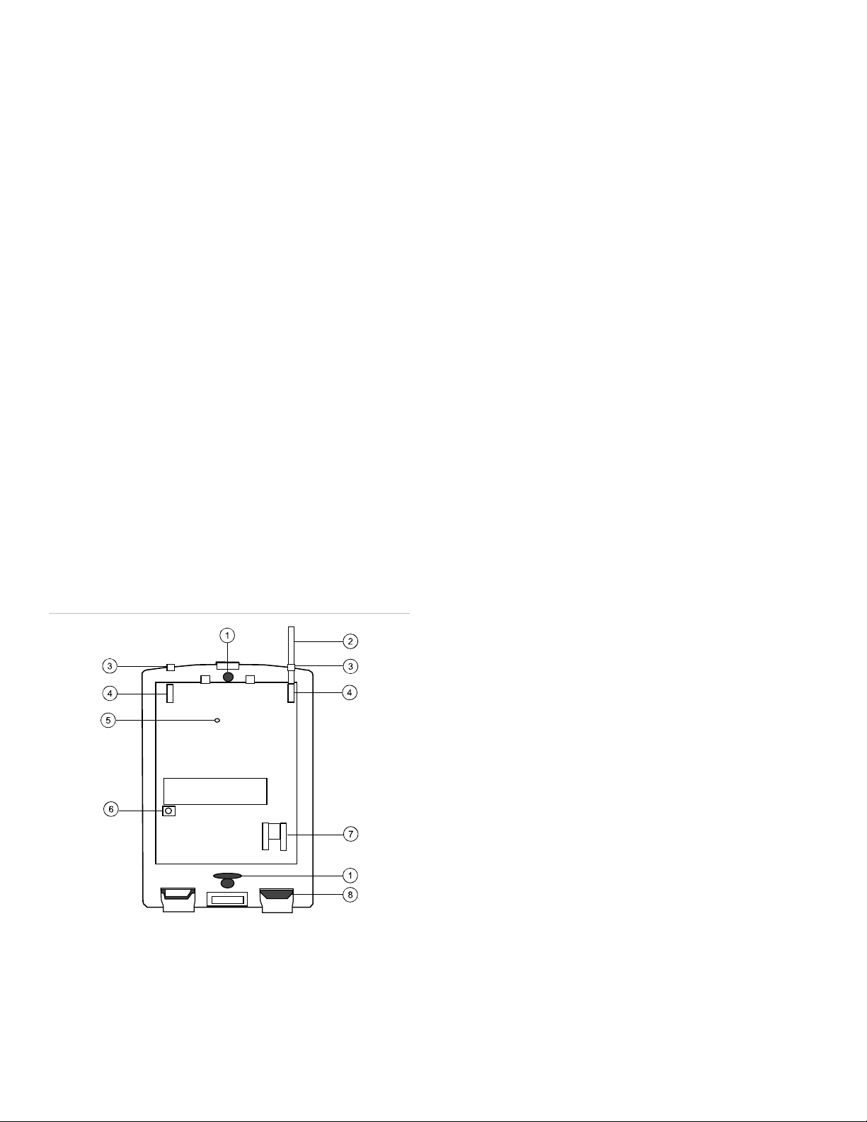
Figure 1: DTIM
1. Remove the DTIM cover and install the antennas. Align
each antenna and push down until bare metal is not
visible.
2. Press Add. The panel announces, “Select from Main
Menu”.
3. Press Sensor/Remote. The panel announces “Press
button on sensor”.
4. Locate the DTIM tamper switch and LED (see Figure 1
above).
Press and release the DTIM tamper switch as follows:
5.
Press three times, holding the tamper switch down on the
third press until the LED flashes three times, then release
after the third press.
Immediately press two times, holding the tamper switch
down on the second press until the LED flashes two times,
then release after the second flash.
Immediately press and hold, then wait for the panel to
beep once indicating it learned the DTIM. Release the
tamper switch.
Timing is the key to success with this step. Do not wait
more than one second between switch activations. If you
wait too long, the LED will not flash and you must start
over. Do not release the tamper switch before the LED is
done flashing or you must start over.
6. Press Sensor/Remote repeatedly until you hear the name
or item you want to use (for example, “Phone
communication module”). Each name may be used more
than once.
7. Press Done when you hear the desired name. The panel
announces “Use numbered keys to enter sensor group”.
8. Enter the two-digit sensor group (08 or 36). The panel
announces the sensor group and the first available sensor
number, then prompts you to press Done to accept.
9. Press Done. The panel confirms programming by
announcing the sensor number, name, and group.
Refer to the Simon documentation for more information on
programming the DTIM with a Simon panel.
Testing DTIM transmitting range
1. Mounting hole
2. Antenna
3. Antenna guide
4. Antenna holder
2 Dialog Telephone Interface Module Installation Sheet
5. LED
6. Tamper switch
7. Phone jack
8. Knockout removed
The following section describes the basic steps for testing
transmitting range from the DTIM to the panel. For complete
testing instructions, refer to the panel’s documentation.
 Loading...