

Interlogix DI601-WT Installation And User Manual
EN
DE
FR
IT
SV
1
2
3
4
5
6
7
DI601-WT Walk Tester Installation and User
Guide
© 2019 UTC Fire & Security Americas Corporation, Inc. 1 / 11 P/N 1069716 (ML) • REV D • ISS 01MAR19
8
9
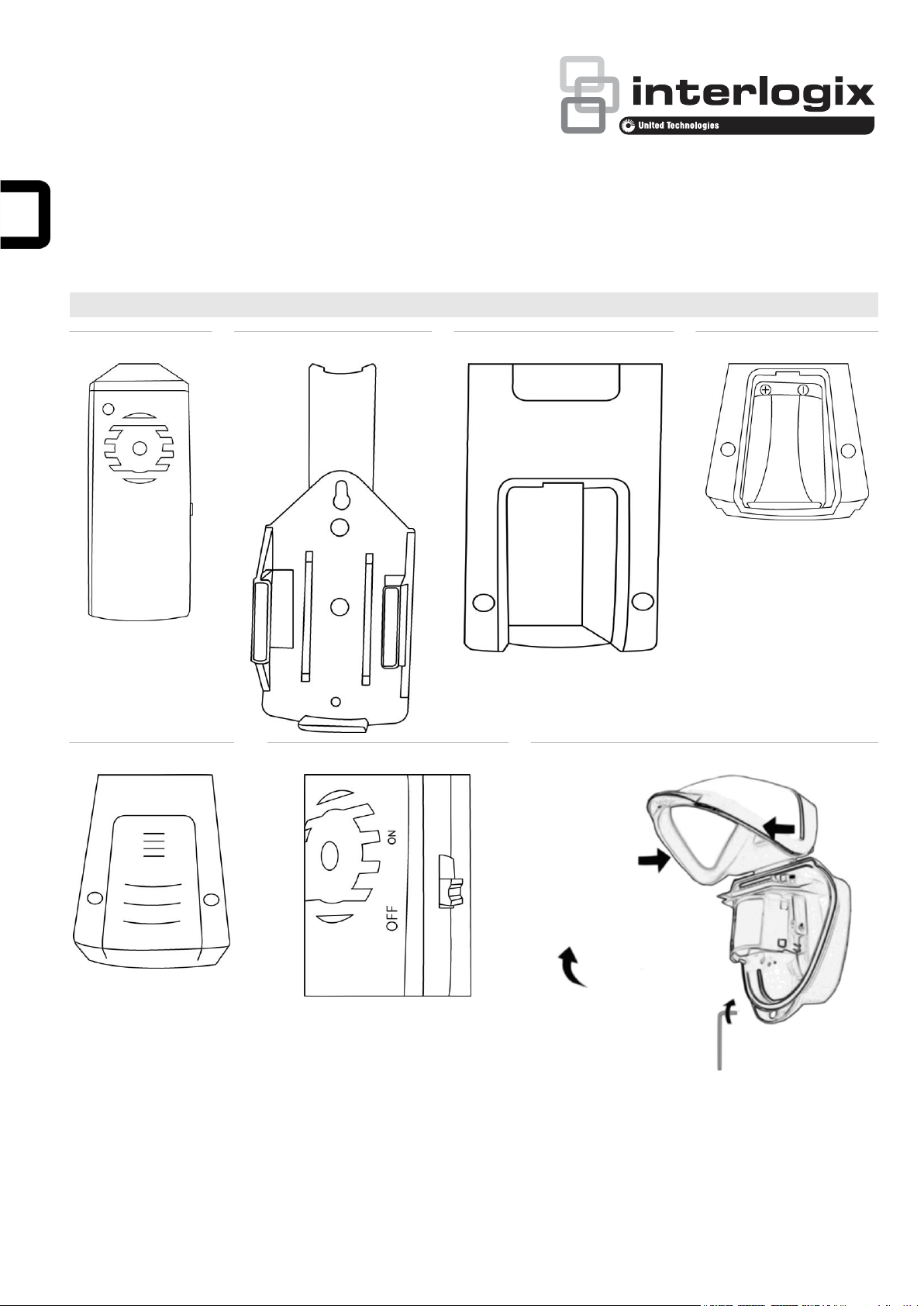
Figure 1: Walk Tester
Figure 2: Walk tester cradle
Figure 3: PP3 battery connector
Figure 4: PP3 battery fitted
Figure 5: Removing battery compartment cover
Figure 6: On / off switch
Figure 7: Detector cover and screw
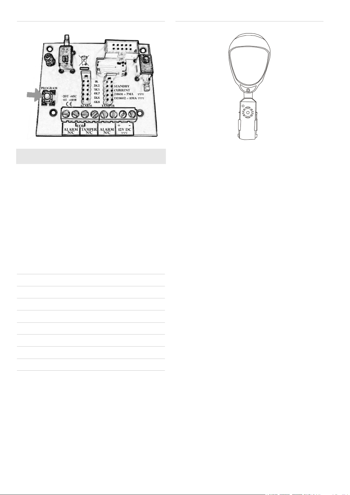
Figure 8: Detector programming button
Figure 9: Walk tester in cradle and fitted to the detector
EN: Installation and User Guide
Description
The DI601-WT walk tester (see Figure 1) is an installation tool
that helps the installer set up a DI601/DDI602 outdoor detector
on site.
Each DI/DDI series outdoor detector has been fitted with an
infrared LED. When activation occurs the LED sends a signal.
The walk tester then receives this signal, and a bright white
LED on the walk tester flashes, and a piezo speaker sounds.
Under normal situations both the LED and the sounder can be
seen and heard up to 50 meters.
4. Switch the walk tester on.
The walk tester lights and sounds whenever the detector
activates.
The detector remains in walk test mode for five minutes after
the last activation.
You can cancel walk test mode by pressing the programming
button on the detector PCB twice.
Mounting cradle
The DI601-WT walk tester comes with a mounting cradle (see
Figure 2).
Figures
Quick guide
Note: Ensure that the cover is on the detector during the walk
test.
1. Put the detector in walk test mode by pressing the
programming button on the detector PCB once.
2. Put the walk tester in the cradle.
3. Clamp the walk tester cradle to the detector using the
detector cover screw.
Powering the walk tester
First, fit a PP3 battery into the walk tester battery compartment
(Figures 3 and 4).
Note: Battery is not included.
This is done by removing the battery compartment cover as
shown in Figure 5.
Please ensure that the On/Off switch on the walk tester is set
to the Off position while connecting the battery (Figure 6).
When the battery is fitted, close the battery compartment (see
Figure 5), and the walk tester is ready for use.
Using the walk tester
Remove the cover from the detector housing by loosening the
stainless steel screw at the bottom of the detector and pressing
the sides of the cover as shown in Figure 7.
This allows access to the programming button shown in
Figure 8 (and lets you verify the presence of the IR emitting
LED).
Put the detector into walk test mode by pressing the
programming button once (see Figure 8). The detector blue
LED will then flash out its current settings. Wait for the flashing
sequence to finish. The detector is now in walk test mode, and
remains in that state for five minutes after the last detection,
thereafter it reverts to normal mode. Walk test can be
cancelled at any time by pressing the programming button
twice.
2 / 11 P/N 1069716 (ML) • REV D • ISS 01MAR19
Power
9 VDC (PP3 Cell)
Note: Battery is not included.
Current:
Standby
0.5 mA
Operating
30 mA
Operating temperature
−20 to +55°C
Protection
Please note that the walk tester is not
waterproof and should not be used in wet
weather conditions. The housing is made
from high impact ABS plastic.
Dimensions
118 x 47 x 25 mm
Manufacturer
Placed on the market by:
UTC Fire & Security Americas Corporation, Inc.
3211 Progress Drive, Lincolnton, NC, 28092, USA
Authorized EU manufacturing representative:
UTC Fire & Security B.V.
Kelvinstraat 7, 6003 DH Weert, Netherlands
Product warnings
and disclaimers
THESE PRODUCTS ARE INTENDED FOR SALE
TO AND INSTALLATION BY QUALIFIED
PROFESSIONALS. UTC FIRE & SECURITY
CANNOT PROVIDE ANY ASSURANCE THAT
ANY PERSON OR ENTITY BUYING ITS
PRODUCTS, INCLUDING ANY “AUTHORIZED
DEALER” OR “AUTHORIZED RESELLER”, IS
PROPERLY TRAINED OR EXPERIENCED TO
CORRECTLY INSTALL FIRE AND SECURITY
RELATED PRODUCTS.
For more information on warranty disclaimers and
product safety information, please check
https://firesecurityproducts.com/policy/productwarning/ or scan the QR code.
Certification
FCC compliance
This device complies with part 15 of the FCC
Rules. Operation is subject to the following two
conditions: (1) This device may not cause harmful
interference, and (2) this device must accept any
interference received, including interference that
may cause undesired operation.
The manufacturer declares that the product
supplied is compliant with the provisions of the
EMC Directive 89/336/EEC amended 92/31/EEC
for Electromagnetic Compatibility, and the
Restriction of Hazardous Substances Directive
(RoHS) 2002/95/EC. A Declaration of Conformity
in accordance with the above directives is held on
file with the manufacturer.
2012/19/EU (WEEE directive): Products marked
with this symbol cannot be disposed of as
unsorted municipal waste in the European Union.
For proper recycling, return this product to your
local supplier upon the purchase of equivalent
new equipment, or dispose of it at designated
collection points. For more information see:
www.utcfssecurityproducts.eu/recycle/
This product may contain a battery that cannot be
disposed of as unsorted municipal waste in the
European Union. See the product documentation
for specific battery information. The battery is
marked with this symbol, which may include
lettering to indicate cadmium (Cd), lead (Pb), or
mercury (Hg). For proper recycling return the
battery to your supplier or to a designated
collection point. For more information see
www.utcfssecurityproducts.eu/recycle/
Abbildung 1: Gehtest-Prüfgerät
Abbildung 2: Halterung des Gehtest-Prüfgeräts
Abbildung 3: Anschluss für 9-V-Blockbatterie
Abbildung 4: Eingesetzte 9-V-Blockbatterie
Abbildung 5: Entfernen der Batteriefachabdeckung
Abbildung 6: Ein/Aus-Schalter
Abbildung 7: Bewegungsmelderabdeckung und Schraube
Hook the mounting bracket of the cradle onto the bottom lip of
the detector and replace the cover. Tighten the screw on the
front cover of the detector to firmly hold the mounting bracket
between the two edges (see Figure 9).
Turn the walk tester on.
The walk tester illuminates and sounds every time the detector
is activated.
For more information on the walk test procedure please refer to
the relevant DI601/DDI602 detector installation sheet.
When finished testing, turn off the walk tester and remove it
and the cradle from the detector. Tighten the screw on the
base of the detector. The DI/DDI series outdoor detector is
now ready.
Specifications
Regulatory information
Contact information
www.utcfireandsecurity.com or www.interlogix.com
For customer support, see www.utcfssecurityproducts.eu
DE: Installations- und
Benutzerhandbuch
Beschreibung
Bei dem Gehtest-Prüfgerät DI601-WT (siehe Abbildung 1)
handelt es sich um ein Installationswerkzeug zur Unterstützung
des Installateurs beim Einrichten des
Außenbewegungsmelders DI601/DDI602 vor Ort.
Jeder Außenbewegungsmelder der DI/DDI Serie weist eine
Infrarot-LED auf. Bei Aktivierung sendet die LED ein Signal.
Das Gehtest-Prüfgerät empfängt dieses Signal, woraufhin am
Prüfgerät eine helle weiße LED blinkt und aus einem
Piezolautsprecher ein Ton erklingt.
Unter Normalbedingungen können die LED und der Ton aus
einer Entfernung von 50 m gesehen bzw. gehört werden.
P/N 1069716 (ML) • REV D • ISS 01MAR19 3 / 11
Abbildungen

Abbildung 8: Programmierungstaste des Bewegungsmelders
Abbildung 9: Gehtest-Prüfgerät mit Halterung am
Bewegungsmelder
Stromversorgung
9 VDC (9-V-Blockbatterie)
Hinweis: Batterie ist nicht im Lieferumfang
enthalten.
Stromaufnahme:
Standby
0,5 mA
Betrieb
30 mA
Betriebstemperatur
−20 bis +55°C
Schutzart
Beachten Sie, dass das Gehtest-Prüfgerät nicht
wasserdicht ist und bei nicht feuchter Witterung
verwendet werden sollte. Das Gehäuse besteht
aus widerstandsfähigem ABS-Kunststoff.
Maße
118 x 47 x 25 mm
Hersteller
Inverkehrbringer:
UTC Fire & Security Americas Corporation, Inc.
3211 Progress Drive, Lincolnton, NC, 28092, USA
Autorisierter EU-Herstellungsrepräsentant:
UTC Fire & Security B.V.
Kelvinstraat 7, 6003 DH Weert, Niederlande
Kurzanleitung
Hinweis: Stellen Sie sicher, dass sich die Abdeckung während
des Gehtests auf dem Bewegungsmelder befindet.
1. Versetzen Sie den Bewegungsmelder in den
Gehtestmodus, indem Sie die Programmierungstaste auf
der Leiterplatte einmal drücken.
2. Setzen Sie das Gehtest-Prüfgerät in die Halterung ein.
3. Befestigen Sie Halterung des Gehtest-Prüfgeräts mithilfe
der Abdeckungsschraube am Bewegungsmelder.
4. Schalten Sie das Gehtest-Prüfgerät ein.
Das Gehtest-Prüfgerät reagiert bei jeder Aktivierung des
Bewegungsmelders mit einem optischen und einem
akustischen Signal.
Nach der letzten Aktivierung verbleibt der Bewegungsmelder
fünf Minuten lang im Gehtestmodus.
Sie können den Gehtestmodus abbrechen, indem Sie die
Programmierungstaste auf der Leiterplatte zweimal drücken.
Erfassung in diesem Status. Anschließend wechselt er zurück
in den Normalmodus. Der Gehtest kann durch doppeltes
Drücken der Programmierungstaste jederzeit abgebrochen
werden.
Hängen Sie den Befestigungsbügel der Halterung an den
unteren Rand des Bewegungsmelders, und klappen Sie die
Abdeckung wieder nach unten. Ziehen Sie die Schraube an
der vorderen Abdeckung des Bewegungsmelders fest, damit
der Befestigungsbügel sicher zwischen den beiden Kanten
gehalten wird (siehe Abbildung 9).
Schalten Sie das Gehtest-Prüfgerät ein.
Das Gehtest-Prüfgerät reagiert bei jeder Aktivierung des
Bewegungsmelders mit einem optischen und einem
akustischen Signal.
Weitere Informationen zum Gehtestverfahren finden Sie auf
dem entsprechenden Installationsdatenblatt für den
Bewegungsmelder DI601/DDI602.
Schalten Sie das Gehtest-Prüfgerät nach Beenden des Tests
aus und entfernen Sie Gerät und Halterung vom
Bewegungsmelder. Ziehen Sie die Schraube an der Unterseite
des Bewegungsmelders fest. Der Außenbewegungsmelder der
DI/DDI Serie ist jetzt einsatzbereit.
Technische Daten
Montagehalterung
Im Lieferumfang des Gehtest-Prüfgeräts DI601-WT ist eine
Montagehalterung enthalten (siehe Abbildung 2).
Anschließen des Gehtest-Prüfgeräts
Setzen Sie zunächst eine 9-V-Blockbatterie in das Batteriefach
des Gehtest-Prüfgeräts ein (Abbildung 3 und 4).
Hinweis: Batterie ist nicht im Lieferumfang enthalten.
Entfernen Sie hierfür die in Abbildung 5 dargestellte
Batteriefachabdeckung.
Stellen Sie sicher, dass sich der Ein/Aus-Schalter des Gehtest-
Prüfgeräts beim Anschließen der Batterie in der Stellung "Off"
Regulatorische Informationen
befindet (Abbildung 6).
Schließen Sie nach dem Einsetzen der Batterie das
Batteriefach (siehe Abbildung 5). Das Gehtest-Prüfgerät ist
nun einsatzbereit.
Verwenden des Gehtest-Prüfgeräts
Entfernen Sie die Abdeckung des
Bewegungsmeldergehäuses, indem Sie die rostfreie Schraube
an der Bewegungsmelderunterseite lösen und wie in
Abbildung 7 dargestellt auf die Abdeckungsseiten drücken.
Auf diese Weise wird die in Abbildung 8 dargestellte
Programmierungstaste freigelegt, und Sie können überprüfen,
ob die Infrarot-LED vorhanden ist.
Versetzen Sie den Bewegungsmelder in den Gehtestmodus,
indem Sie die Programmierungstaste einmal drücken (siehe
Abbildung 8). Die blaue LED des Bewegungsmelders blinkt
gemäß der aktuellen Einstellungen. Warten Sie, bis die
Blinksequenz endet. Der Bewegungsmelder befindet sich jetzt
im Gehtestmodus und verbleibt fünf Minuten nach der letzten
4 / 11 P/N 1069716 (ML) • REV D • ISS 01MAR19
 Loading...