

Page 1
Installation Instructions
Model D2300CPS
Fiber Optic Interface
Fire Safety
INTRODUCTION
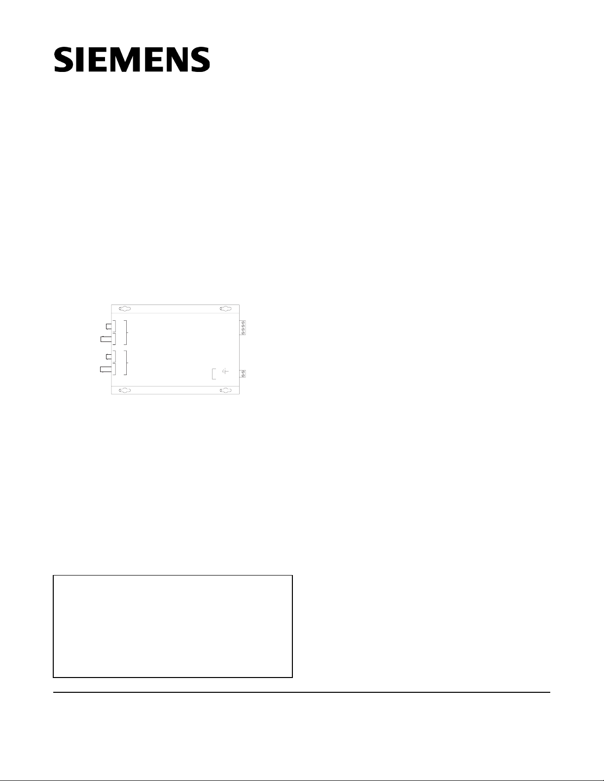
The Model D2300CPS from Siemens Building Technologies, Inc. (See Figure 1) is a Fiber Optic interface
for the MXL’s RS-485 network (MNET or XNET) or
the FireFinder XLS network (HNET or XNET). It uses
a two-fiber (duplex) pair between each device. The
D2300CPS can function as either a repeater or an
end point unit.
D2300CPS
A
B
RS485
POWER
DATA
REC
DATA
XTMR
DATA
REC
DATA
XTMR
WARNING: This module is NOT backwards
compatible with the existing 2300CP. This unit
uses +24VDC. Make sure to read the front of the
module and connect to the correct voltage.
Otherwise, serious damage to the unit will result.
Figure 1
D2300CPS Module
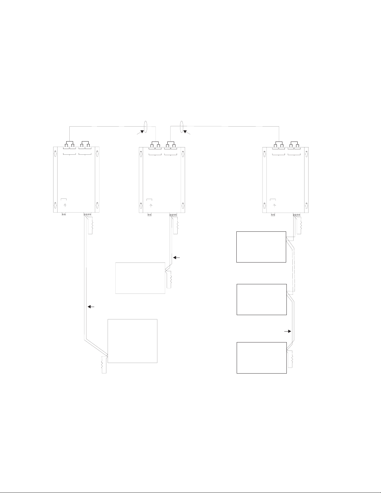
The D2300CPS can operate in either a daisy chain
(See Figure 2) or star configuration (See Figure 3).
This allows for network configurations that are not
possible with the RS-485 network alone.
POWER
(DO NOT USE) -4
(DO NOT USE) -3
-DATA-2
+DATA-1
+24 VDC
-2
-1
MOUNTING
The D2300CPS has four keyhole slots for #6 screws.
Mount the device in the locations listed below using
the four #6 screws provided.
A bracket (P/N 500-692880) is available for mounting
the D2300CPS in any MXL enclosure that will accept
a MOM-4 (See Figure 4). This bracket has the same
footprint as the MOM-4 and accommodates two
D2300CPS modules. An assembly kit is included with
the bracket that contains four nuts and eight screws.
Mount the bracket in the enclosure with the four nuts
at the positions labeled X (See Figure 4). Start four of
the 6-32 screws and slip the keyhole slots in the
D2300CPS
System 3 style rails that mount on an MBR-2 or MME-3
backbox (P/N MSR-1) are also available and can be
used for mounting the D2300CPS with the System 3
MPFO Bracket. Up to three brackets can be installed on
a single rail.
A bracket, Model D2300-MP, is available for mounting
two D2300CPS modules in any FireFinder XLS CAB
enclosure. The D2300-MP fits in the same footprint as
a CC-5 and mounts to the CAB-MP. A hardware kit is
provided for attaching the D2300-MP to the CAB-MP
and mounting two D2300CPS modules onto the
D2300-MP. Mount the D2300CPS modules prior to
installing the D2300-MP onto the CAB-MP. Note that
when using two D2300CPS modules, the center two
mounting holes on each D2300CPS share the two
center studs on the D2300-MP (See Figure 5).
over them. Tighten the four screws.
WARNING:
The D2300CPS module is not listed for use by
Factory Mutual. Applications requiring fiber connectivity of voice modules/systems are therefore
not Factory Mutual listed.
WARNING:
Do not use the D2300CPS with CXL Systems.
Siemens Building Technologies, Inc.
8 Fernwood Road
Florham Park, New Jersey 07932
P/N 315-050018-0
ELECTRICAL CONNECTIONS
POWER INPUT
The D2300CPS uses filtered or unfiltered 24 VDC.
The D2300CPS can only be powered from the
sources listed in Table 1 on page 6.
Siemens Building Technologies, Ltd.
2 Kenview Boulevard
Brampton, Ontario L6T 5E4 CN
Page 2
DUPLEX OPTICAL FIBER
POWER BUDGET - MAX LOSS
-13 dB 62.5/125 FIBER
- 9 dB 50/125 FIBER
DUPLEX OPTICAL FIBER
POWER BUDGET - MAX LOSS
-13 dB 62.5/125 FIBER
- 9 dB 50/125 FIBER
CONNECTION
POWER
DATA
XTM
DATA
REC
B
D2300CPS
POWER
+24 VDC
-2
-1
NO
DATA
REC
DATA
XTMR
A
(DO NOT USE) -4
(DO NOT USE) -3
+DATA-1
-DATA-2
EOLR
120 OHMS, 1/4W
P/N 140-820150
RS-485
32 NODES MAX
SUPERVISED
SUPERVISED
PSR-1
POWER
DATA
XTMR
DATA
REC
B
D2300CPS
POWER
+24 VDC
-2
-1
DATA
XTMR
DATA
REC
A
(DO NOT USE) -4
(DO NOT USE) -3
+DATA-1
-DATA-2
EOLR
120 OHMS, 1/4W
P/N 140-820150
RS-485
32 NODES MAX
SUPERVISED
EOLR
120 OHMS, 1/4W
P/N 140-820150
SUPERVISED
RCC-1
RCC-1
CONNECTION
POWER
DATA
XTMR
DATA
REC
B
D2300CPS
POWER
+24 VDC
-2
-1
NO
DATA
XTMR
DATA
REC
A
(DO NOT USE) -4
(DO NOT USE) -3
+DATA-1
-DATA-2
EOLR
120 OHMS, 1/4W
P/N 140-820150
USE THE 120 ¼ W, 5%
EOL RESISTOR ASSEMBLY,
AS APPLICABLE:
P/N 140-820150 (MMB-1/-2)
OR P/N 140-049099 (MMB-3)
W,
32 NODES MAX
MMB
SUPERVISED
PSR-1
Figure 2
Daisy Chain Configuration (MNET Shown)
2
RS-485
EOLR
120 OHMS, 1/4W
P/N 140-820150
Page 3

CONNECTION
POWER
DATAPXTMR
DATAPREC
B
DUPLEX OPTICAL FIBER
POWER BUDGET - MAX LOSS
-13 dB 62.5/125 FIBER
- 9 dB 50/125 FIBER
NO
DATAPXTMR
DATAPREC
A
CONNECTION
DATA
XTMR
DATA
REC
B
NO
POWER
DATA
XTMR
DATA
REC
A
CONNECTION
POWER
DATA
XTMR
DATA
REC
B
NO
DATA
XTM
DATA
REC
A
SUPERVISED
TO ADDITIONAL
D2300CPS
MODULES
D2300CPS
POWER
+24 VDC
-2
-1
USE THE 120 ¼ W, 5%
EOL RESISTOR ASSEMBLY,
AS APPLICABLE:
P/N 140-820150 (MMB-1/-2)
OR P/N 140-049099 (MMB-3)
(DO NOT USE) -4
(DO NOT USE) -3
+DATA-1
-DATA-2
W,
D2300CPS
POWER
+24 VDC
-2
-1
RS-485
32 NODES MAX
SUPERVISED
MMB
D2300CPS
(DO NOT USE) -4
(DO NOT USE) -3
+DATA-1
-DATA-2
POWER
+24 VDC
-1
(DO NOT USE) -4
(DO NOT USE) -3
+DATA-1
-DATA-2
-2
PSR-1
EOLR
PSR-1
120 OHMS, 1/4W
P/N 140-820150
Figure 3
Star Configuration (MNET Shown)
3
Page 4

X
-1
-2
-DATA-2
+DATA-1
+24VDC
(DONOT USE) -4
(DONOT USE) -3
POWER
BRACKET
P/N 500-692880
D2300CPS
A
B
DATAPREC
DATAPREC
DATAPXTMR
POWER
-DATA-2
+DATA-1
(DONOT USE) -4
(DONOT USE) -3
DATAPXTMR
-1
-2
+24VDC
POWER
OMM-1
D2300CPS
A
B
DATAPREC
DATAPREC
DATAPXTMR
DATAPXTMR
POWER
X
WARNING
DISCONNECT POWER
PRIOR TO
REMOVING
TERMINAL
BLOCK PROTECTION
Figure 4
Mounting the D2300CPS in an MBR-2 or MME-3 Backbox
FIBER OPTIC CABLE
D2300-MP
POWER
DATA
XTMR
DATA
XTMR
DATA
REC
DATA
B
D2300CPS D2300CPS
POWER
+24 VDC
-2
-1
REC
A
POWER
(DO NOT USE) -4
(DO NOT USE) -3
+DATA-1
+24 VDC
-DATA-2
-1
POWER LIMITED HNET/XNET
ROUTE AS SHOWN
_
TB1
P5
1
1
P4
34
7
PSC-12
RESET
POWER
MODULE FAIL
CAN FAIL
HNETFAIL
GND FAULT
24V 12AFAIL
24V 4AFAIL
+
1
-
HNET
BATTERY
—
O
OFF
19
13
12
+
+
3
2
-
-
ON
TB2
24
18
Z
O
N
E
1
Z
O
N
E
2
+
-
DLC
RESET
POWER
CARDFAIL
HNETFAIL
GNDFAULT
ALARM
TROUBLE
ZONESSTATUS
CLASSA OPEN
CLASSA RETURN
SHORT
CLASSA OPEN
CLASSA RETURN
SHORT
+
1
2
-
HNET
+
3
-
POWER
DATA
XTMR
DATA
XTMR
DATA
REC
DATA
B
REC
A
(DO NOT USE) -4
(DO NOT USE) -3
+DATA-1
-DATA-2
-2
NIC-C
RESET
POWER
CARDFAIL
CANFAIL
HNETFAIL
XNETFAIL
GNDFAULT
LOOPA FAIL
LOOPB FAIL
ACTIVENETWORKS
CAN
HNET
XNET
HNET/XNETSTYLE
STYLE7
STYLE4
GROUNDFAULT
ENABLED
DISABLED
NETWORK
PORT
+
+
+
3
1
2
-
-
-
HNET
+
6
2
1
TB3
12
P12
H N GND
2
1
P9
_
+
_
TB4
+
CAB-1
Figure 5
Mounting the D2300CPS in a CAB-1 Backbox
4
Page 5

POWER BUDGET - MAX LOSS
SUPERVISED
-13 dB 62.5/125 FIBER
- 9 dB 50/125 FIBER
N.C.
N.C.
DATA
REC
DATA
XTMR
DATA
REC
DATA
XTMR
DATA
REC
DATA
XTMR
DATA
REC
DATA
XTMR
A
B
A
B
D2300CPS
D2300CPS
END POINT
FACP
RS-485 NETWORK
MNET/HNET/XNET
(SEE FIGURES 7,8&9)
REPEATER
FACP
POWER BUDGET - MAX LOSS
SUPERVISED
-13 dB 62.5/125 FIBER
- 9 dB 50/125 FIBER
N.C.
N.C.
DATA
REC
DATA
XTMR
DATA
REC
DATA
XTMR
A
B
D2300CPS
END POINT
FACP
Figure 6
Wiring the D2300CPS as both a Repeater and End Point Unit
RS-485 RATINGS:
8V P-P
150mA MAX
80 OHMS MAX
18 AWG MIN
(DO NOT USE)
(DO NOT USE)
D2300CPS
(DO NOT USE)
(DO NOT USE)
D2300CPS
(DO NOT USE)
(DO NOT USE)
D2300CPS
-DATA
+DATA
-DATA
+DATA
-DATA
+DATA
-4
-3
-2
-1
-4
-3
-2
-1
-4
-3
-2
-1
EOLR
120 OHMS, 1/4W
P/N 140-820150
STYLE 4 MNET
SUPERVISED
W,
USE THE 120 ¼ W, 5%
EOL RESISTOR ASSEMBLY,
AS APPLICABLE:
P/N 140-820150 (MMB-1/-2)
OR P/N 140-049099 (MMB-3)
SUPERVISED
EOLR
120 OHMS, 1/4W
P/N 140-820150
1234
SUPERVISED
120 OHMS, 1/4W
P/N 140-820150
EOLR
TB1
(DO NOT USE)
4
(DO NOT USE)
3
2
1
REFER TO NET-7
INSTALLATIONINSTRUCTIONS
P/N 315-091914
MMB
RS-485 RATINGS:
8V P-P
150mA MAX
80 OHMS MAX
18 AWG MIN
TB1
NET-7
MOM-4
STYLE 7 MNET
Figure 7
Wiring the RS-485 MNET Network in Style 4 and Style 7
5
Page 6

1elbaT
METSYSECRUOSREWOP
LXM21-95BT;5-41BT:2-BMM
SLXredniFeriF-,+4BT:21-CSP
ECRUOSREWOP
3-DAP-,+XUA
53-SP6-51BT
21-95BT;-,+9BT:3-BMM
6-3;2-13BT:1-RSP
+4BT:21-XSP
-,
For non-power limited wiring, the PLM-35 (Installation
Instructions P/N 315-093495) must be used to comply
with NFPA 70 per NEC 760. All wiring must be in
accordance with Article 760 of NEC or local building
codes.
For additional information on the MXL/MXLV System,
refer to the MXL/MXLV Manual, P/N 315-092036.
24 VDC CURRENT CALCULATION (MXL ONLY)
The 24 VDC output ratings for the MMB/SMB and PSR-1 are:
MMB-2/-3 6A at 24 VDC (MPS-6); 12A at 24 VDC (MPS-12)
SMB-2 6A at 24 VDC (MPS-6); 12A at 24 VDC (MPS-12)
PSR-1 6A at 24 VDC (MPS-6); 12A at 24 VDC (MPS-12)
The following modules all draw current from the 24 VDC supply. Add the value for each module that is installed in
the enclosure where the D2300CPS is to be installed. Be sure to include the D2300CPS in this calculation.
CDV42EVITCA
ELUDOM
1-MCAAm58
1-CSAAm14
2-CSAAm16
003-IMCAm0
4-MRCAm57
4-MSC
4-MZC
SPC0032DAm75
4-/2-BKMAm0
4-TENAm0
7-TENAm0
M7-TENAm0
7-IOMAm021
61-DOMxamAm058
MxamAm23
61-DI
1-MIPAm0
1-CTBAm44
1-MCRAm031
03-CAZW03taA3
1-CCOAm71
B8-1CZAm071
B8-2CZAm243
BA4-2CZAm761
BA4-3CZAm861
B8-TCZAm8
ELUDOM
TNERRUCYTITNAUQLATOT
xamA5.1+Am43
ucricrep
ti
Am027
mralanisenoz4
7
LATOT
6
Page 7

(DO NOT USE)
(DO NOT USE)
D2300CPS*
-DATA
+DATA
EOLR
-4
-3
-2
-1
*
120 OHMS, 1/4W
P/N 140-820150
SUPERVISED
RS-485 RATINGS:
8V P-P
150mA MAX
80 OHMS MAX
18 AWG MIN
*
(DO NOT USE)
(DO NOT USE)
D2300CPS
-4
-3
-DATA
-2
+DATA
-1
120 OHMS, 1/4W
P/N 140-820150
SUPERVISED
EOLR
Figure 8
Wiring the RS-485 XNET Network
in Style 4 and Style 7 (MXL)
RS-485 NETWORK
The RS-485 MNET, XNET and HNET networks
connect to the D2300CPS on the terminal block with
the markings +DATA (1) and -DATA(2). Terminals 3
and 4 are not used. For Style 4 networks one
D2300CPS is needed at each Fiber Optic drop. For
Style 7 networks two D2300CPS modules are needed
at each drop.End of line devices are required on each
RS-485 pair in the system. Install them at the extreme
ends of each pair. Refer to Figures 7 and 8 (MXL)
and Figure 9 (FireFinder XLS) for wiring instructions
and ratings for both Style 4 and Style 7.
NOTE: Positive and negative ground fault detected
when terminals shorted to earth.
FIBER CONNECTIONS
*
OMIT THIS EQUIPMENT FOR STYLE 4 XNET
EOLR
120 OHMS, 1/4W
P/N 140-820150
1234
REFER TO NIM-1R OR NIM-1W
INSTALLATION INSTRUCTIONS
P/N 315-092953 OR P/N 315-099165,
AS APPLICABLE
TB3
NIM-1R/-1W
MOM-4
When installing the fiber pairs, each fiber must
connect between the transmit data (DATA XTMR) on
one D2300CPS and the receive data line (DATA
REC) on the other D2300CPS.
The D2300CPS fiber connection is classified as Style
DCLB per ULC-527.
INDICATORS
The D2300CPS has five LED indicators for Power
and Status.
The LEDs are located on the side of the module with
the Fiber Optic connectors. The Power LED is green
and lights whenever there is 24 VDC. Both channels A
and B have a yellow and green LED. The green LED
indicates that the D2300CPS is transmitting data on that
channel. The yellow LED lights when data is received.
The D2300CPS can function as both a repeater and an
end point unit. When used as an end point, connect
to the fiber connectors labeled A. Make no connection to the B connectors. In the repeater mode, use
both pairs of connectors, A and B.
Two Fiber Optic cables are required between each pair
of D2300CPS modules. Use a high quality duplex Fiber
Optic cable containing either 50/125 or 62.5/125 fiber.
Duplex fiber optic cable has two cables in a single
shield similar to electrical zip cord. Use ST style fiber
connectors. Please contact the fiber manufacturer
regarding instructions for terminating the fiber.
ELECTRICAL RATINGS
tnerruCeludoMCDV42evitcAAm75
tnerruCeludoMCDV42ybdnatSAm75
Input Power 18-31 VDC, 57mA max
Battery Power 24 VDC, 57mA max
RS-485 8V (P-P), 150mA max
Transmitter Power 20µW (-17dBm)
(62.5/125 Fiber)
7
Page 8

(DO NOT USE)
(DO NOT USE)
-DATA
+DATA
EOLR
-4
-3
-2
-1
120 OHMS, 1/4W
P/N 140-820150
D2300CPS
RS-485 RATINGS:
8V P-P
150mA MAX
80 OHMS MAX
18 AWG MIN
NO EOLR REQUIRED AT THE NIC-C
STYLE 4 HNET/XNET
(DO NOT USE)
(DO NOT USE)
-DATA
+DATA
D2300CPS
-4
-3
-2
-1
SUPERVISED
DO NOT USE
12345678
910111213141516
DO NOT USE
NIC-C
ONE SLOT OF CC-5/CC-2
17 18 19 20 21 22 23 24
DO NOT USE
EOLR
120 OHMS, 1/4W
P/N 140-820150
(DO NOT USE)
(DO NOT USE)
D2300CPS
RS-485 RATINGS:
8V P-P
150mA MAX
80 OHMS MAX
18 AWG MIN
NO EOLR REQUIRED AT THE NIC-C
-DATA
+DATA
-4
-3
-2
-1
SUPERVISED
SUPERVISED
DO NOT USE
12345678
910111213141516
DO NOT USE
DO NOT USE
NIC-C
ONE SLOT OF CC-5/CC-2
STYLE 7 HNET/XNET
17 18 19 20 21 22 23 24
DO NOT USE
Figure 9
Wiring the RS-485 HNET or XNET Network in Style 4 and Style 7 (FireFinder XLS)
P/N 315-050018-0
Page 9

Contacting us
For help installing, operating, maintaining, and troubleshooting this product, refer to this document and any
other documentation provided. If you still have questions, contact us during business hours (Monday through
Friday, excluding holidays, between 5 a.m. and 5 p.m. Pacific Time).
Table 3. Sales and support contact information
Sales Technical support
Phone:
Toll-free: 888.437.3287 in the US, including Alaska and Hawaii;
Puerto Rico; Canada.
Outside the toll-free area: 503.885.5700.
E-mail
Fax
888.329.0331 888.329.0332
techsupport@interlogix.com
Note: Be ready at the equipment before calling.
Online
Another great resource for assistance with your Interlogix product is our online publication library. To access
the library, go to our website at the following location:
http://www.interlogix.com
1
1. Many Interlogix documents are provided as PDFs (portable document format). To read these documents, you will
need Adobe Reader, which can be downloaded free from Adobe’s website at www.adobe.com.
Page 10

Copyright © 2011 UTC Fire & Security. All rights reserved.
r
Trademarks and
patents
Manufacture
Certification
FCC compliance Class A: This equipment has been tested and found to comply with
Interlogix and IFS names and logos are trademarks of
UTC Fire & Security.
Other trade names used in this document may be trademarks or
registered trademarks of the manufacturers or vendors of the
respective products.
UTC Fire & Security Americas Corporation, Inc.
2955 Red Hill Avenue, Costa Mesa, CA 92626-5923, USA
Authorized EU manufacturing representative:
UTC Fire & Security B.V.
Kelvinstraat 7, 6003 DH Weert, The Netherlands
N4131
the limits for a Cla
Rules. These limits are designed to provide reasonable protection
against harmful interference when the equipment is operated in a
commercial environment. This equipment generates, uses, and can
radiate radio frequency energy and, if not installed and used in
accordance with the instruction manual, may cause harmful
interference to radio communications. Operation of this equipment in
a residential area is likely to cause harmful interference in which
case the user will be required to correct the interference at his own
expense.
ss A digital device, pursuant to part 15 of the FCC
ACMA compliance Notice! Thi
product may cause radio interference in which case the user may be
required to take adequate measures.
Canada This Class A digital apparatus complies with Canadian ICES-003.
Cet appareil numérique de la classe A est conforme à la norme
NMB-0
European Union
directives
Contact information For contact information, see www.interlogix.com.
2004/108/EC (EMC directive): Hereby, UTC Fire & Security
decl
ares that this device is in compliance with the essential
requirements and other relevant provisions of Directive
2004/108/EC.
2002/96/EC (WEEE directive): Products marked with this symbol
cannot be disposed of as unsorted municipal waste in the European
Union. For proper recycling, return this product to your local supplier
upon the purchase of equivalent new equipment, or dispose of it at
designated collection points. For more information see:
www.recyclethis.info.
s is a Class A product. In a domestic environment this
03 du Canada.
 Loading...