

Page 1

D19110SHR
D19110SHR-R3
D19130SHR
D19130SHR-R3
IFS Fiber Module
Installation & Operation
Instructions
P/N 1062844 • REV B • ISS 01AUG11
Page 2
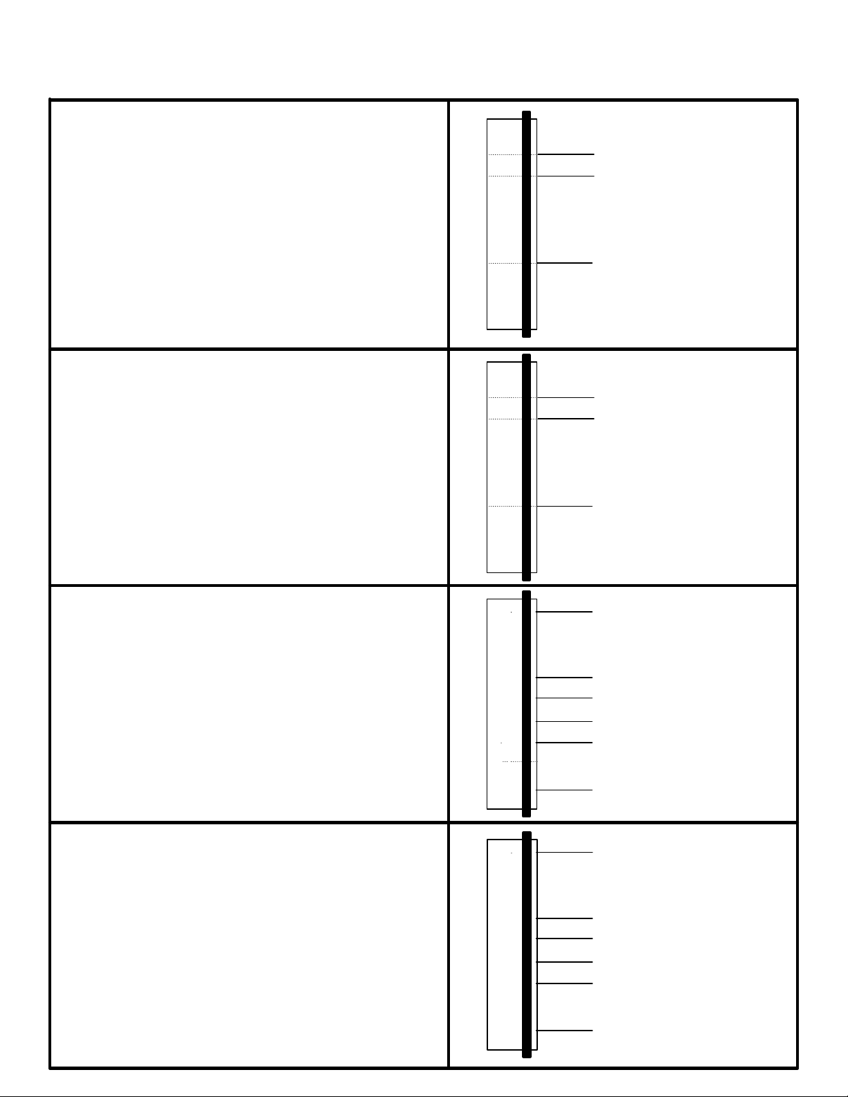
RS - 232 DATA
(DCE MODE)
GROUND
DATA INPUT
7
6
5
4
3
2
1
8
20
RS - 232 DATA
(DTE MODE)
GROUND7
6
5
4
3
2
1
8
20
DATA OUTPUT
CONTROL LINES
DATA OUTPUT
DATA INPUT
8
6
5
4
3
2
1
9
20
RTS
CHASSIS GRD
CTS
DSR
DTR
DCD
D19100SHR Series
(DCE MODE)
CONTROL LINES
(DTE MODE)
1
2
3
4
5
6
8
9
CHASSIS GRD
RTS
CTS
DSR
DCD
20
DTR
Page 3
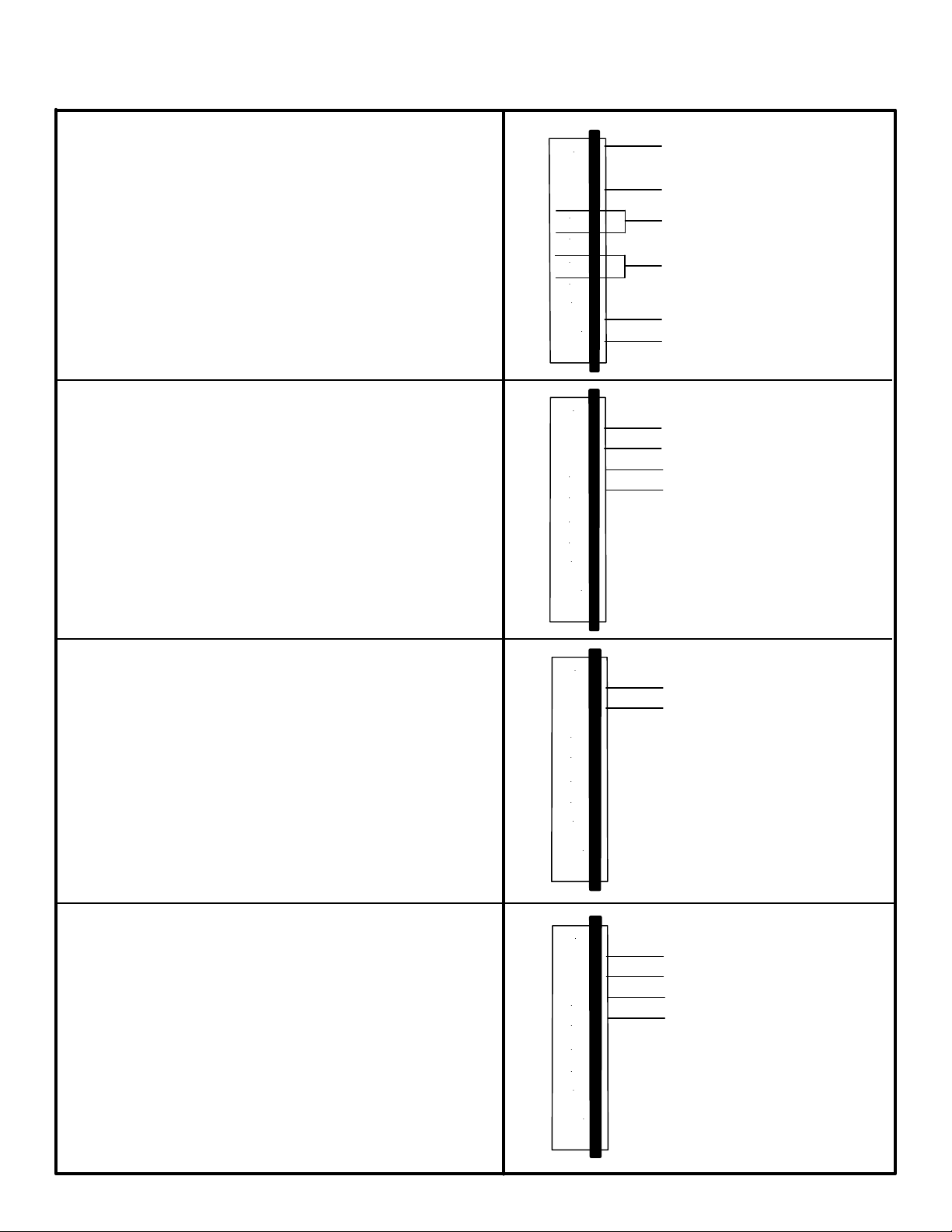
OTHER CONNECTIONS*
* For further information see Appendix
RS-422 DATA
2w RS-485 DATA
4w RS-485 DATA
D19100SHR Series
9
10
11
12
13
21
22
23
24
14
15
16
17
+ 5 VOLTS JABBER RESET
MAY BE TEMPORARILY
CONNECTED TO PIN 24 TO
RESET ANTI-STREAMING
"FAIL" CONTACT CLOSURE,
NORMALLY CLOSED
MASTER RELAY ACTIVE MODE
CONTACT CLOSURE
CONNECT TO PIN 24 FOR
MASTER CONTROL MODE
SIGNAL GROUND
DATA IN +
DATA IN DATA OUT +
DATA OUT -
14
15
14
15
16
17
DATA IN / OUT +
DATA IN / OUT-
DATA IN +
DATA IN DATA OUT +
DATA OUT -
Page 4
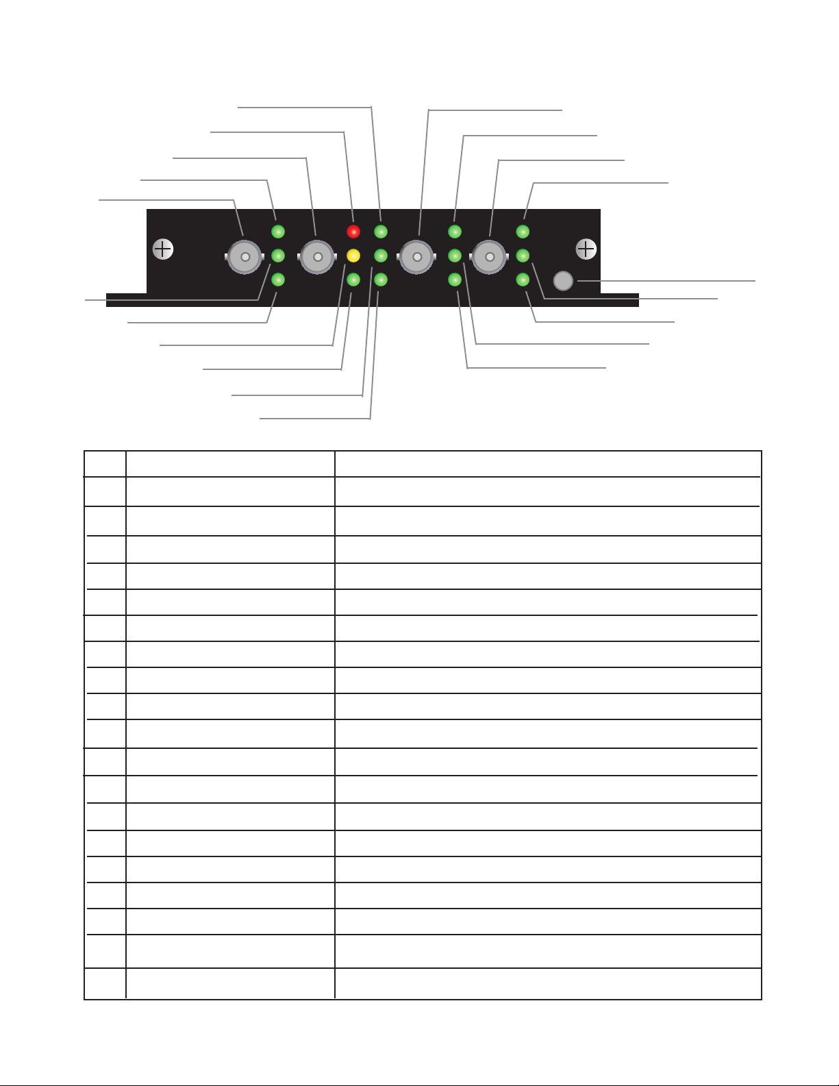
D19100SHR
NOTE: WITHOUT PROPER FIBER
CONNECTION, LED's DO NOT INDICATE
CORRECT OPERATIONAL STATUS.
B
A
J
K
L
ACReceive A
B
RTS
C
D
M
N
E
F
G
H
I
T
S
R
Q
P
O
A: Optical Input
LED illuminates when RTS is in active state.
Transmit B
D Fail
E A Direction*
F Receive B
G CTS
H Transmit A
I Not Used (OFF)
J RX A
K TX A
L Loss - of - Data
M Power
N B Direction*
O Set as Master
P TX B
Q RX B
R Set as Slave
B: Optical Output
LED illuminates when one of the receive ports stops receiving
optical energy or in a jabber error state.
LED illuminates Green when complete optical path
is established in A direction.
B: Optical Input
LED illuminates when CTS is in active state.
A: Optical Output
N/A
LED illuminates when optical data is present on A input.
LED illuminates when data is present on A output.
LED illuminates upon loss of electrical input data.
LED illuminates when power is applied.
LED illuminates Green when complete optical path
is established in B direction.
LED illuminates
LED illuminates when data is present on B output
LED illuminates when optical data is present on B input.
LED illuminates
S Jabber Error
T Reset Switch
* LED illuminates yellow when upstream data is interrupted in that fiber loop.
LED off when break in fiber of that loop.
LED illuminates
Press to reset jabber alarm state.
Page 5
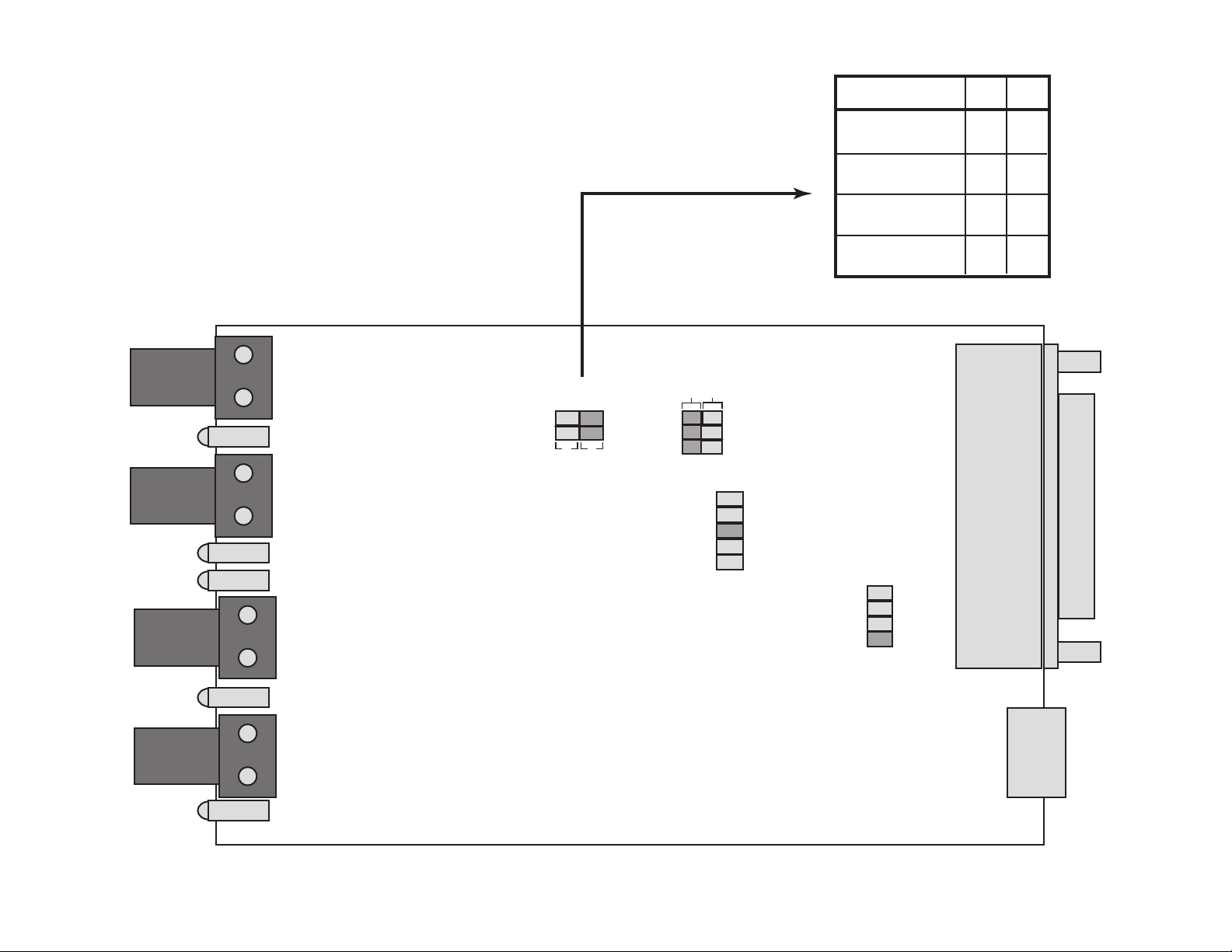
Internal Jumper Settings
#1
#2
D19100WDM Series
#2
#1
JMP 3
B
A
JMP 2
JMP 4
NOT
USED
USED
JABBER
RTS
LOD
B A
64 SEC
32 SEC
16 SEC
8 SEC
4 SEC
JABBER TIME
RS232
RS422
RS485 (2w)
RS485 (4w)
JMP 5
LOD TIME
64 SEC
32 SEC
16 SEC
8 SEC
B
B
BBA
A
A
A
Page 6

A
D19100SHR Series
B
1 2
Auto
Manual DTE Slave
C ED
ACPower Connector
B
Data / Control Lines Connector
Auto / Manual Selector Switch
D DCT / DTE Selector Switch
E Master / Slave Selector Switch
DCE Master
Page 7

D19100SHR Series
1 2
Auto
Manual DTE Slave
MANUAL: Use this setting on all units in a single master
configuration or on a slave unit.
AUTO: Use this setting on a master unit in a redundant
master configuration.
All slave units should always be set to manual.
DCE Master
Page 8

D19100SHR Series
1 2
Auto
DCE Master
Manual DTE Slave
DCE: RS232 connections are configured as
Data Communications Equipment
DTE: RS232 connections are configured as
Data Terminal Equipment
Page 9

D19100SHR Series
1 2
Auto
DCE Master
Manual DTE Slave
When Auto/Manual switch is set to Manual,
sets master and slave units.
In a single master configuration.
When Auto/Manual switch is set to Auto,
Master sets primary master,
Slave sets redundant master.
Page 10

D19100SHR Series
FAILURE LOGIC TABLE
If break in: Loop LED Master Slave 1 Slave 2 Slave 3
Y
G
Y
G
OFF
A1
A2
A Y
B G
A
B
A
OFF
G
Y
G
Y
G
G
G
Y
G
OFF
G
G
A3
B
G
G
G
G
NOTE:
Grayed out areas
indicate good
operational loop
in noted direction.
Multiple fiber breaks
follow the failure logic
for that loop.
A4
B1
B2
B3
B4
B3
A
B
A
Y
G
G
G
G
G
G
G
G
G
G
G
KEY:
B
A
B
A
B
A
B
Y
G
Y
G
Y
G
Y
Y
G
Y
G
OFF
G
G
Y
G
OFF
G
G
G
G
OFF
G
G
G
G
G
G
G - Green
Y - Yellow
SLAVE 2
D19100 Series
TxB
ifs
203.426.1180
www.ifs.com
International
Fiber
Systems
Incorporated
RxB
B2
SLAVE 1
D19100 Series
ifs
203.426.1180
www.ifs.com
TxB
International
Fiber
Systems
Incorporated
RxB
TxA
RxA
B4
A2
A1
RxA
TxA
RxB
MASTER
D19100 Series
ifs
203.426.1180
www.ifs.com
International
Fiber
Systems
Incorporated
TxA
RxA
TxB
A3
A4
RxA
TxA
B1
TxB
D19100 Series
ifs
203.426.1180
www.ifs.com
D19100 Series
RxB
SLAVE 3
International
Fiber
Systems
Incorporated
Page 11

INSTALLATION INSTRUCTIONS FOR ADDITIONAL COMPONENTS NEEDED
TO MEET EMISSION REQUIREMENTS ON THE D19100SHR SERIES PRODUCTS.
INSTALL AS SHOWN.
D19100SHR
DB 25 DATA CABLE
(CUSTOMER SUPPLIED)
RADIO SHACK PART NO. 26-240
OR EQUIVALENT
12 VDC POWER CABLE SUPPLIED
1) INSTALL A SEPARATE SUPPLIED
EMI FILTER CLAMP AS SHOWN
2) DIGI-KEY PART NUMBER
240-2065-ND OR STEWARD PART
NUMBER 28A0640-0A0
OR EQUIVALENT
DB 25 DATA CABLE
(CUSTOMER SUPPLIED)
RADIO SHACK PART NO. 26-240
OR EQUIVALENT
1) INSTALL A SEPARATE SUPPLIED
EMI FILTER CLAMP AS SHOWN
2) DIGI-KEY PART NUMBER
240-2065-ND OR STEWARD PART
NUMBER 28A0640-0A0
OR EQUIVALENT
1) INSTALL A SEPARATE SUPPLIED
EMI FILTER CLAMP AS SHOWN
2) DIGI-KEY PART NUMBER
240-2076-ND OR STEWARD PART
NUMBER 28A2029-0A0
OR EQUIVALENT
D19100SHR-R3
Page 12

Appendix
Automatic Switching Master
The automatic switching master feature gives the Self Healing Ring the capability of having two
redundant masters for the purpose of increasing fault tolerance Each master node may be connected
to individual host computers, or to a single host computer using a simple Y connection. Master nodes
may be located anywhere in the ring. In a redundant master configuration, one master will always be
in active mode while the other in standby mode. The active master will transmit and receive
RS232/485/422 data as usual while the master in standby mode will ignore data at at it’s data input
and it’s data output will be inactive and stay in tristate. If a master in active mode fails for any reason,
through automatic switching, the other master will enter active mode.
Loss-of-Data Detection
The loss-of-data detection feature increases fault tolerance in the RS232 data path from master to
host computer. This feature is only applicable when automatic switching master is enabled. A loss-ofdata jumper setting on the SHR sets a timeout on host data input inactivity. If the data input from the
host computer remains inactive for a set amount of time, a break in the data path is assumed. In this
case, a master in active mode will enter standby mode allowing the other master to become active.
Jabber Error Detection (Anti Streaming)
Used to detect an out-of-control RS232 data source. In some systems, an RS232 data source should
not continuously transmit for more than a specified amount of time. This feature is used to disable an
out-of-control data source by monitoring how long the CTS/RTS input line remains active. If it remains
active for more than the set amount of time, the RS232 input is gate off. Once an error occurs, the
error is latched. The only way it may be reset is by manually pressing the Anti-Streaming Reset button
or cycling power. In order for Jabber Error Detection to gate off the RS232 input, CTS/RTS must be
enabled.
Fail Relay
This solid-state relay is normally closed and only opens during a failure. On a slave, the fail state indicates that lock cannot be achieved one or both of the fiber inputs. On a master, the fail state indicates
that lock cannot be achieved one or both of the fiber inputs, or that a fiber loop is reversed indicating a
failure somewhere in the ring. On both a master and slave, a Jabber Error is considered as a fail state
and opens the relay.
RTS/CTS
The RTS/CTS input is always looped around and drives the RTS/CTS output for use with computers
that require hardware flow control. The only exception to this is when Auto Switching Master is
enabled and the unit is in standby mode. In this case, the RTS/CTS RS232 output driver is tristate so
that a Y cable may be used to connect the output from both masters together. If a Y cable is not used,
the RTS/CTS input is used to gate RS232 input data. In this case, RS232 input data would be gated
off unless CTS/RTS is in the active state.
Master Relay
When Auto Switching Master is disabled, the solid-state relay is closed when the unit is configured as
a master and open when configured as a slave. By enabling Auto Switching Master, the unit becomes
a master. But in this case, the relay is closed when the unit is in active mode and open in standby
mode.
Page 13

FCC Compliance
This device complies with Part 15 of the FCC Rules. Operation is subject to the following two
conditions: (1) This device may not cause harmful interference, and (2) this device must accept
any interference received, including interference that may cause undesirable operation.
Changes or modifications not expressly approved by International Fiber Systems, Inc. could void
the user’s authority to operate the equipment.
NOTE: This equipment has been tested and found to comply with the limits for a Class A
digital device, pursuant to Part 15 of the FCC Rules. These limits are designed to provide
reasonable protection against harmful interference when the equipment is operated in a
commercial environment. This equipment generates, uses and can radiate radio frequency
energy and, if not installed and used in accordance with the instruction manual, may cause
harmful interference to radio communications. Operation of this equipment in a residential
area is likely to cause harmful interference in which case the user will be required to
rect the interference at his own expense.
cor-
CLASS 1 LASER PRODUCT
(For purposes of IEC 60825-1)
Complies with FDA Performance Standard for Laser Products
Title 21
Code of Federal Regulations
Subchapter J
Comprehensive
Lifetime Warranty
(a) Seller warrants to the original End User that products and any
services furnished hereunder will be free from defects in material
and workmanship as of the date of delivery, and will conform to
Seller’s published technical specications. The foregoing shall
apply only to failures to meet said warranties which appear within
that period of time during which the Products are installed in their
original installation for the original End User and operator of such
Products; provided, however, that in the event of product discontinuance, warranty support is limited to ve (5) years from the
announcement of discontinuance. Notwithstanding the preceding
sentence, the duration of the warranty period for
manufactured by Seller (e.g., ber optic cabling, test equipment,
power supplies or batteries) shall be the warranty period oered by
the original manufacturer, if any.
(b) The conditions of any tests shall be mutually agreed upon and
Seller shall be notied of, and may be represented at, all tests that
may be made. The warranties and remedies set forth herein are
conditioned upon (a) proper storage, installation, use and maintenance, and
Seller and (b) Buyer promptly notifying Seller of any defects and,
if required, promptly making the product available for correction.
(c) If any product or service fails to meet the foregoing warranties,
Seller shall thereupon correct any such failure either at its option,
conformance with any applicable recommendations of
products not
(i) by repairing any defective or damaged product or parts of the
products, or (ii) by making available any necessary repaired or
replacement products or parts thereof. Any repaired or replacement
part or product shall be warranted for the remaining period of the
original Warranty Period. Seller shall pay, or credit Buyer for, the
cost of freight for all return shipments of products or parts to
Buyer. Where a failure cannot be corrected by Seller's reasonable
eorts, the parties will negotiate an equitable adjustment in price.
(d) The preceding paragraph sets forth the exclusive remedies for
claims based on defect in or failure of products or services,
whether the claim is in contract, indemnity, warranty, tort
(including Seller's negligence), strict liability or otherwise and
however instituted. Upon the expiration of the warranty period,
all such liability shall terminate and BUYER shall have a reasonable time, within thirty days after the warranty period, to give
written notice of any defects which appeared during the warranty
period. The foregoing warranties are exclusive and in lieu of all
other warranties, whether written, oral, implied or statutory.
NO IMPLIED OR STATUTORY WARRANTY OF
MERCHANTABILITY OR FITNESS FOR PARTICULAR
PURPOSE SHALL APPLY. Seller does not warrant any
products or services of others which BUYER has designated.
Page 14

Contacting us
For help installing, operating, maintaining, and troubleshooting this product, refer to this document and any
other documentation provided. If you still have questions, contact us during business hours (Monday through
Friday, excluding holidays, between 5 a.m. and 5 p.m. Pacific Time).
Sales and support contact information
North
America
Toll-free: 855.286.8889 in the US, including Alaska and Hawaii;
Puerto Rico; Canada.
Outside the toll-free area: 503.885.5700.
E-mail: techsupport@interlogix.com
Europe
Australia
Select Contact Us at www.utcfssecurityproducts.eu
security.tech.support@interlogix.com.au
Note: Be ready at the equipment before calling.
Online
Another great resource for assistance with your Interlogix product is our online publication library. To access
the library, go to our website at the following location:
http://www.interlogix.com/transmission
1
1. Many Interlogix documents are provided as PDFs (portable document format). To read these documents, you will
need Adobe Reader, which can be downloaded free from Adobe’s website at www.adobe.com.
Page 15

Product Disassembly Instructions for WEEE
Per European Directive 2002/95/EC Waste Electrical and
Electronic Equipment
Required Tools:
One number 2 Phillips (crosstip) screwdriver.
One number 2 flat screwdriver.
For the enclosed box version:
1. Locate and remove box cover securement screws. Usually, but not limited to, at least
4 screws.
2. Lift off box top cover.
3. Locate and remove securement screws for printed circuit board.
4. If there are multiple boards to the assembly, continue removing securement screws
until none are left.
5. Lift off printed circuit board.
6. Disassembly of box version of product is complete.
For rack version:
1. Locate and remove securement screws for printed circuit board. Usually, but not
limited to, at least 4 screws.
2. If there are multiple boards to the assembly, continue removing securement screws
until none are left.
3. Lift off printed circuit board(s).
4. Disassembly of rack card version of product is complete.
Page 16

Copyright © 2011 UTC Fire & Security. All rights reserved.
r
Trademarks and
patents
Manufacture
Certification
ACMA compliance Notice! Thi
Canada This Class A digital apparatus complies with Canadian ICES-003.
European Union
directives
Interlogix and IFS names and logos are trademarks of
UTC Fire & Security.
Other trade names used in this document may be trademarks or
registered trademarks of the manufacturers or vendors of the
respective products.
UTC Fire & Security Americas Corporation, Inc.
2955 Red Hill Avenue, Costa Mesa, CA 92626-5923, USA
Authorized EU manufacturing representative:
UTC Fire & Security B.V.
Kelvinstraat 7, 6003 DH Weert, The Netherlands
N4131
product may cause radio interference in which case the user may be
required to take adequate measures.
Cet appareil numérique de la classe A est conforme à la norme
NMB-0
2004/108/EC (EMC directive): Hereby, UTC Fire & Security
decl
requirements and other relevant provisions of Directive
2004/108/EC.
03 du Canada.
ares that this device is in compliance with the essential
s is a Class A product. In a domestic environment this
2002/96/EC (WEEE directive): Products marked with this symbol
cannot be disposed of as unsorted municipal waste in the European
Union. For proper recycling, return this product to your local supplier
upon the purchase of equivalent new equipment, or dispose of it at
designated collection points. For more information see:
www.recyclethis.info.
Contact information For contact information, see www.interlogix.com.
 Loading...