

Page 1
Forward Facing Camera Installation
Manual
1038137 D January 2013
© 2013 UTC Fire & Security Americas Corporation, Inc.
Content
Introduction 1
Installation 1
Wiring 3
Adjusting the camera angle 3
Focusing the camera 4
Troubleshooting 4
FCC Complicance 4
Contact information 5
Mounting bracket template 5
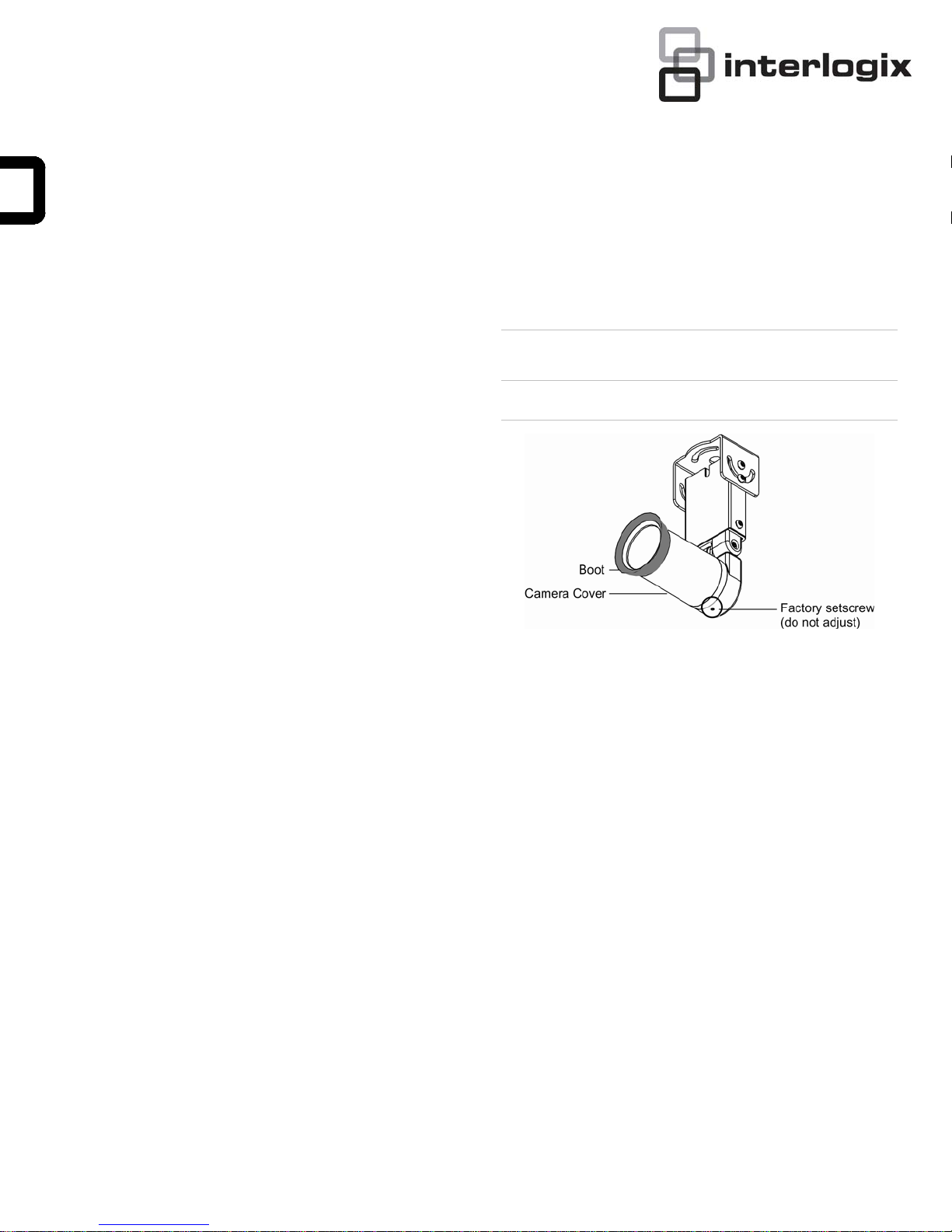
Caution: Do not adjust the setscrew (Figure 1). It is for
factory use only.
Figure 1: Factory setscrew and cover boot
Introduction
This is the Installation Manual to the MobileView (TM)
Forward Facing Camera. Read these instructions before
installing or operating this product.
Note: A qualified service person, complying with all
applicable codes, should perform all required hardware
installation.
This manual provides installation and operation
information. To use this document, you must have the
following minimum qualification:
• A basic knowledge of CCTV systems and
components; and
• A basic knowledge of electrical wiring and lowvoltage electrical hookups.
Installation
You can mount the camera from above or from below
(inverted). Some mounting surface might need to be
reinforced to minimize the vibration of the camera. In
these installations, place a tapping plate behind the
mounting surface.
To mount the camera, do the following:
1. Push the rubber boot onto the camera cover (Figure
1).
2. Position the unit on the mounting surface so that the
lens points toward the area you want to view.
Note: Consider the camera’s (with the boot
attached) proximity to the vehicle’s windshield, close
enough to prevent glare and far enough away to not
vibrate the windshield (about 3/4 inch
recommended).
3. Use the provided template (Figure 12 on page 4) to
mark the positions of the mounting and cable entry
holes on the mounting surface.
4. While following your local codes, cut the cable entry
hole and drill and prepare the mounting holes for the
type of surface and fasteners (not provided) being
used.
Note: We recommend attaching rivnuts and running
10/32 screws to mount the camera.
5. If you are hanging the unit from above, attach the
unit with fasteners (not provided) that are
1 Forward Facing Camera Installation Manual
Page 2
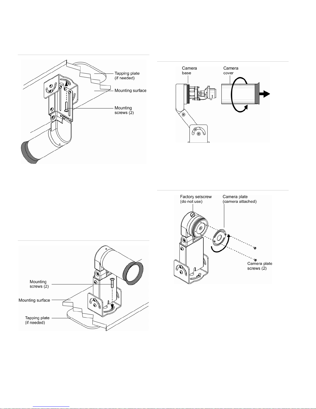
appropriate for the mounting surface (Figure 2). If
you are inverting the camera assembly, see
Mounting the camera from below.
Figure 2: Mounting the camera from above
Note: Apply blue Loctite before tightening screws that
have been loosened.
Mounting the camera from below
• Connect a laptop computer to the DVR and use the
Mobile View software program.
3. Turn the camera cover counterclockwise to remove
the camera cover from the camera base (Figure 4).
Figure 4: Accessing the camera base
4. Remove the two camera plate screws and rotate the
camera plate 180 degrees to invert the attached
camera (Figure 5).
Figure 5: Inverting the camera
To mount the camera from below so that the camera is
inverted, do the following:
1. Attach the unit with fasteners (not provided) that are
appropriate for the mounting surface (Figure 3).
Figure 3: Mounting the camera from below
2. Access live look-in mode to see the camera’s field-of-
view. To access the mode, do one of the following:
• Connect a Mobile View test kit to the back of the box
of the DVR and use the kit’s monitor or
5. Rotate the camera plate 180 degrees to invert the
attached camera.
6. Use the test kit or laptap computer monitor to adjust
the camera’s field of view.
7. Reinstall the camera plate screws.
8. Reattach the camera cover.
9. Disconnect the test kit or laptop computer.
2 Forward Facing Camera Installation Manual
Page 3
Wiring
To connect the cables, do the following:
1. Run the provided RG179 cable between the
vehicle’s DVR and camera, and feed it out through
the cable entry hole.
Caution: Hold onto the camera when removing the
bracket screws.
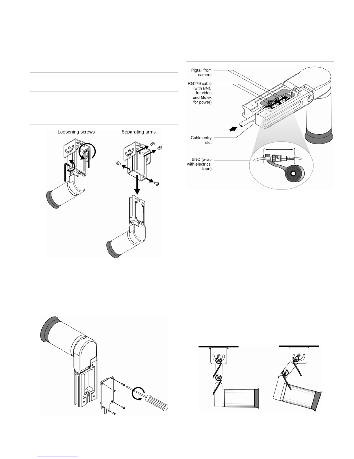
2. Using the provided Allen wrench, remove the
bracket screws from the camera arm (Figure 6).
Figure 6: Separating the camera arms
5. Feed the RG179 cable through the cable entry slot
and into the connection box (Figure 8 on page 3).
Figure 8: Connecting the cables
3. Separate the lower and upper camera arms (Figure
6).
4. Remove the connection box screws to remove the
connection box cover (Figure 7).
Figure 7: Accessing the connection box
6. Make cable connections as shown in Figure 8.
7. Wrap electrical tape around the BNC (Figure 8).
Cover all metal. This prevents metal-to-metal contact
that could short the video line.
8. Reattach the connection box cover (Figure 7 on
page 3). Secure the cover screws with blue Loctite.
9. Insert the lower arm into the upper arm and secure
the camera arm with the bracket screws (Figure 6 on
page 3). Secure the screws with blue Loctite.
Adjusting the camera angle
To adjust the camera angle, do the following:
1. Loosen the upper and lower pivot screws (Figure 9).
Figure 9: Adjustingthe camera angle
Forward Facing Camera Installation Manual 3
2. Set the camera to the desired angle.
Page 4

3. Tighten all pivot screws. Secure the screws with blue
Loctite.
Note: To keep the camera in focus, you may have to
adjust the focus ring while you tighten the
thumbscrew.
Focusing the camera
The camera has a varifocal lens (2.9 to 8 mm) and can
also be adjusted for focus. To focus the camera, do the
following:
1. Access live look-in mode to see the camera’s fieldof-view.
2. Turn the camera cover counterclockwise to remove
the camera cover from the camera base (Figure 10).
Figure 10: Removing the camera cover
9. Reattach the camera cover.
10. Make final adjustments to the angle of the camera
assembly and secure all screws with blue Locite.
See Adjusting the camera angle.
11. Disconnect the test kit or laptop computer.
Troubleshooting
• There is no video or it is intermittent.
The BNC connector is probably shorted or the wires
are pinched.
Ensure that the BNC connector inside the
connection box is wrapped with electrical tape to
prevent metal-to-metal contact with the camera
housing (Figure 8).
Ensure that the pigtail wires coming from the camera
are not pinched in the hinge.
• Video is upside down or misaligned on the monitor.
The camera is not inverted or aligned. Invert and/or
align the camera. See Mounting the camera from
below on page 1.
3. Loosen the zoom ring thumbscrew (Figure 11).
Figure 11: Adjusting focus and zoom settings
4. Turn the zoom ring to set the desired field of view.
5. Tighten the zoom ring thumbscrew.
6. Loosen the focus ring thumbscrew (Figure 11).
7. Turn the focus ring to set the desired focus.
• Video is shaky on the monitor.
There is excessive vehicular vibration of the camera.
Reinforce the mounting surface with a tapping plate
placed behind the mounting surface to minimize
vibration.
FCC Complicance
This equipment has been tested and found to comply
with the limits for a Class A digital device, pursuant to
part 15 of the FCC Rules. These limits are designed to
provide reasonable protection against harmful
interference when the equipment is operated in a
commercial environment. This equipment generates,
uses, and can radiate radio frequency energy and, if not
installed and used in accordance with the installation
instructions, may cause harmful interference to radio
communications.
You are cautioned that any changes or modifications not
expressly approved by the party responsible for
compliance could void the user’s authority to operate the
equipment.
8. Tighten the focus ring thumbscrew.
4 Forward Facing Camera Installation Manual
Page 5
Contact information
North America:
855-286-8889
techsupport@interlogix.com
Latin America:
561-998-6114
latam@interlogix.com
Web site:
www.interlogix.com/customer-support
EMEA:
See specific Country listings at:
www.utcfssecurityproducts.eu/support
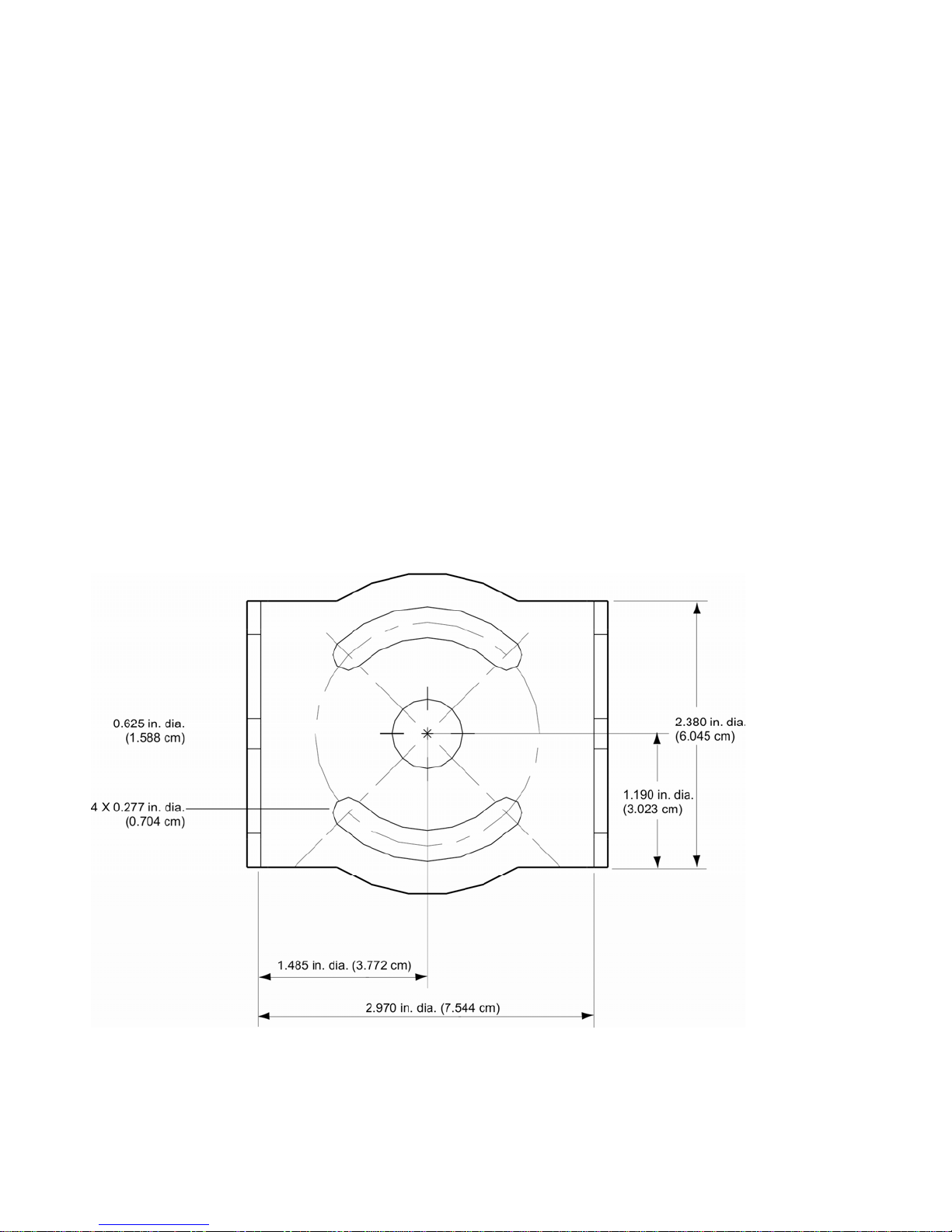
Mounting bracket template
Use the mounting bracket template to mark the positions
of the mounting and cable entry holes on the mounting
surface.
Forward Facing Camera Installation Manual 5
 Loading...