


Model 94x, 97x Proximity Reader
Installation Manual

Copyright Copyright © 2008, GE Security Inc. All rights reserved.
This document may not be copied or otherwise reproduced, in whole or in part,
except as specifically permitted under US and international copyright law,
without the prior written consent from GE.
Document number/460157001P (January 2008).
Disclaimer THE INFORMATION IN THIS DOCUMENT IS SUBJECT TO CHANGE WITHOUT
Trademarks
and patents
Intended use Use this product only for the purpose it was designed for; refer to the data sheet
compliance
Regulatory
NOTICE. GE ASSUMES NO RESPONSIBILITY FOR INACCURACIES OR OMISSIONS
AND SPECIFICALLY DISCLAIMS ANY LIABILITIES, LOSSES, OR RISKS, PERSONAL OR
OTHERWISE, INCURRED AS A CONSEQUENCE, DIRECTLY OR INDIRECTLY, OF THE
USE OR APPLICATION OF ANY OF THE CONTENTS OF THIS DOCUMENT. FOR THE
LATEST DOCUMENTATION, CONTACT YOUR LOCAL SUPPLIER OR VISIT US ONLINE
AT WWW.GESECURITY.COM.
This publication may contain examples of screen captures and reports used in
daily operations. Examples may include fictitious names of individuals and
companies. Any similarity to names and addresses of actual businesses or
persons is entirely coincidental.
GE and the GE monogram are registered trademarks of General Electric.
Model 94x/97x Proximity Reader product and logo are trademarks of
GE Security.
Other trade names used in this document may be trademarks or registered
trademarks of the manufacturers or vendors of the respective products.
and user documentation. For the latest product information, contact your local
supplier or visit us online at www.gesecurity.com.
FCC
This equipment has been tested and found to comply with the limits for a
Class A digital device, pursuant to part 15 of the FCC Rules. These limits are
designed to provide reasonable protection against harmful interference when
the equipment is operated in a commercial environment. This equipment
generates, uses, and can radiate radio frequency energy and, if not installed
and used in accordance with the instruction manual, may cause harmful interference to radio communications.
You are cautioned that any changes or modifications not expressly approved
by the party responsible for compliance could void the user's authority to
operate the equipment .

Contents
Introduction . . . . . . . . . . . . . . . . . . . . . . . . . . . . . . . . . . . . . . . . . . . . . . . . . . 1
Safety. . . . . . . . . . . . . . . . . . . . . . . . . . . . . . . . . . . . . . . . . . . . . . . . . . . . . . . . 2
Radio interference. . . . . . . . . . . . . . . . . . . . . . . . . . . . . . . . . . . . . . . . . . . . . .2
Electrostatic discharge (ESD) precaution. . . . . . . . . . . . . . . . . . . . . . . . .2
Product features . . . . . . . . . . . . . . . . . . . . . . . . . . . . . . . . . . . . . . . . . . . . . . 3
System requirements. . . . . . . . . . . . . . . . . . . . . . . . . . . . . . . . . . . . . . . . . . 4
Technical specifications . . . . . . . . . . . . . . . . . . . . . . . . . . . . . . . . . . . . . . . 5
Parts list . . . . . . . . . . . . . . . . . . . . . . . . . . . . . . . . . . . . . . . . . . . . . . . . . . . . . 6
Installation overview . . . . . . . . . . . . . . . . . . . . . . . . . . . . . . . . . . . . . . . . . . 7
Mounting the reader . . . . . . . . . . . . . . . . . . . . . . . . . . . . . . . . . . . . . . . . . . 8
Back-to-back readers. . . . . . . . . . . . . . . . . . . . . . . . . . . . . . . . . . . . . . . . . . .9
External tamper feature . . . . . . . . . . . . . . . . . . . . . . . . . . . . . . . . . . . . . . . . 9
Mounting diagrams. . . . . . . . . . . . . . . . . . . . . . . . . . . . . . . . . . . . . . . . . . . .10
Configuring the reader . . . . . . . . . . . . . . . . . . . . . . . . . . . . . . . . . . . . . . . 20
Switch settings . . . . . . . . . . . . . . . . . . . . . . . . . . . . . . . . . . . . . . . . . . . . . . . .20
Selecting reader power level . . . . . . . . . . . . . . . . . . . . . . . . . . . . . . . . . . .20
Selecting operating mode. . . . . . . . . . . . . . . . . . . . . . . . . . . . . . . . . . . . . .26
Selecting beeper sound level. . . . . . . . . . . . . . . . . . . . . . . . . . . . . . . . . . .27
Connecting the reader. . . . . . . . . . . . . . . . . . . . . . . . . . . . . . . . . . . . . . . . 28
Pinouts . . . . . . . . . . . . . . . . . . . . . . . . . . . . . . . . . . . . . . . . . . . . . . . . . . . . . . .28
Wiring diagrams. . . . . . . . . . . . . . . . . . . . . . . . . . . . . . . . . . . . . . . . . . . . . . .29
Testing the reader . . . . . . . . . . . . . . . . . . . . . . . . . . . . . . . . . . . . . . . . . . . 36
Troubleshooting the reader . . . . . . . . . . . . . . . . . . . . . . . . . . . . . . . . . . . 38
All installations . . . . . . . . . . . . . . . . . . . . . . . . . . . . . . . . . . . . . . . . . . . . . . . .38
Unsupervised modes only . . . . . . . . . . . . . . . . . . . . . . . . . . . . . . . . . . . . .41
Supervised modes only . . . . . . . . . . . . . . . . . . . . . . . . . . . . . . . . . . . . . . . .41
Regulatory approvals . . . . . . . . . . . . . . . . . . . . . . . . . . . . . . . . . . . . . . . . 44
UL . . . . . . . . . . . . . . . . . . . . . . . . . . . . . . . . . . . . . . . . . . . . . . . . . . . . . . . . . . . .44
CE . . . . . . . . . . . . . . . . . . . . . . . . . . . . . . . . . . . . . . . . . . . . . . . . . . . . . . . . . . . .45
i

Model 94x/97x Proximity Reader
ii
Installation Manual
Figures
Figure 1. Recommended Additional Mounting Instructions
Figure 2. Model 940 Reader - Gang Box Mounting.........................12
Figure 3. Model 940 Reader - Direct Wall Mounting.......................13
Figure 4. Model 941 Reader - Gang Box Mounting.........................14
Figure 5. Model 941 Reader - Direct Wall Mounting.......................15
Figure 6. Model 970/972 Reader - Gang Box Mounting...............16
Figure 7. Model 970/972 Reader - Direct Wall Mounting.............17
Figure 8. Model 971/973 Reader - Gang Box Mounting...............18
Figure 9. Model 971/973 Reader - Direct Wall Mounting.............19
Figure 10. Model 94x/97x Reader, J1 Connector and DIP
Figure 11. (PCB Assembly P/N 100079001 manufactured |
Figure 12. Wiring Diagram, Model 94x/97x
Figure 13. Wiring Diagram, Model 94x/97x
Figure 14. Wiring Diagram, Model 94x/97x
Figure 15. Typical Installation (Internal to the microcontroller)
Figure 16. Typical Installation (External to the microcontroller)
for External Tamper Switch Activation..............................11
Switch Locations (PCB Assembly P/N 100079002
manufactured 12/02 or later)................................................22
prior to 12/02)................................................................................23
Supervised F/2F Mode...............................................................30
Unsupervised F/2F Mode.........................................................32
Unsupervised Wiegand Mode ..............................................34
Using Shielded Cable/Drain Wire......................................... 46
Using Shielded Cable/Drain Wire......................................... 46

Introduction 1
Introduction
This manual is an installation guide for the GE Models 940, 941,
970, 971, 972, and 973 proximi ty rea ders. Thr oughout this g uide,
the abbreviation 94x represents reader models 940 and 941. The
abbreviation 97x represents reader models 970, 971, 972, and
973.
The 94x and 97x readers while similar in functionality offer a
variety of features making them suitable for different
applications. The 94x and 97x readers are designed to mount on
standard U.S. gang boxes. The 94x readers are single-gang box
size. The 97x readers are sized for larger dual gang box
installation, offer greater badge read range, and a keypad option.
Models 940 and 970 give t he greatest all-around b adge read rang e
for their respective sizes, making th em ideal for most
installations.
Models 941 and 971 are tuned for ins ta ll at ion on meta l mounting
plates. The standar d metal mounti ng plate shie lds t he re ader from
the effects of a metal wall, which would otherwise dramatically
reduce the read ra nge. The opt ional back- to-ba ck me tal mounting
plate shields the reade r from the ef fects of a metal wall and makes
the reader unidirectional; ideal for direct back-to-back reader
installations.
Models 972 and 973 are dual gang size readers, identical to the
970 and 971 respective ly, except f or their built-i n twelve-po sition
keypad. This feature makes these readers ideal for installations
requiring keypad PIN entry in addition to a valid badge read.
Model 94x/97x Proximity Reader
2
Installation Manual
Safety
Radio interference
WARNING: This is an FCC Class A product. In a domestic
environment, this product may cause radio
interference, in which case, the user may be
required to take adequate measures.
Electrostatic discharge (ESD) precaution
WARNING: Circuit board components are vulnerable to damage
by electrostatic discharge (ESD). ESD can cause
immediate or subtle damage to sensitive electronic
parts. An electrostatic charge can build up on the
human body and then discharge when you touch a
board. A discharge can be produced when walking
across a carpet and touching a board, for example.
Before handling any board, make sure you dissipate
your body’s charge by touching ground. This
discharges any static electricity build-up.

Product features 3
Product features
The GE Model 94x/97x Reader offers:
• Intelligent bidirectional communication between the
reader and microcontroller, which can be accomplished
up to 5,500 feet.
TM
• The ability to read all I SO ProxLite
Entrée badges and key tags.
• Field changeable DIP switches allow all 94x and 97x
readers to operate in one of four distinct operating
modes: Wiegand (4001), F/2F, Supervised, and Silent
Supervised.
• Rugged, weather-resistant, molded ABS construction
with integral backplate.
• Standard 12V operation.
• A clear, logical user interface with three LEDs and a
switch selectable beeper with volume control.
• Built-in tamper alarm also detects removal from wall.
• External tamper alarm option.
• Tactile keypad (Models 972 and 973 only) for Personal
Identification Number (PIN) input.
, ProxLite, and

Model 94x/97x Proximity Reader
4
Installation Manual
System requirements
Host software
Microcontrollers • Micro/2
Microcontroller
firmware
Badge and keytag
formats
• Secure Perfect
•Picture Perfect
•Micro/4
•Micro/5-PX with 2RP or 8RP
• Micro/5-PXN with 2RP or 8RP
• M5PXNplus with 2RP or 8RP
• Micro/PX-2000
• Micro/PXN-2000
• M2000PXNplus
• M3000PXNplus with 2RP or 8RP
• For Micro/2 and Micro/4:
Secure Perfect: Version 5 or later
Picture Perfect: Version 1.7.0 or later
• For Micro/5-PX, Micro/5-PXN, Micro/PX-2000
and Micro/PXN-2000:
Secure Perfect: 3.1.0.6 or later
Picture Perfect: 1.7.0 or later
•ISO ProxLite
•ProxLite
•Entrée
•Proximity Perfect
®
Edition 3.0 or later
™
1.7 or later
Note: Proximity Perfect cards are obsolete
however they are supported by the Model
94x/97x readers.

Technical specifications 5
Technical specifications
For UL compliant installation notes, refer to “UL” on page 44.
Operating
temperature range
Relative humidity 5% to 95% (non-condensing)
Physical dimensions
Model 94x
Model 97x
Index of protection IP55
Color Light gray and black
Power supply Nominal 12VDC, 75mA, 150mA or 200mA
Cable specifications Belden 8725 or equivalent, 20 AWG minimum,
Maximum cabling
distance
Read range Determined by the reader’s power level setting and
a
-31 F (-35 C) to +151 F (+66 C)
(HxWxD)
4.75" (121 mm) x 2.9" (74 mm) x 0.90" (23 mm)
4.75" (121 mm) x 5.5" (140 mm) x 0.90" (23 mm)
dependent on the power setting selected.
See Table 1 “Power level switch settings,” on page 24
shielded pairs
The maximum cable distance between the reader
and the microcontroller is influenced by a number of
factors including wire gauge and reader power level
setting. See Table 3 “Cable distances,” on page 25.
other environmental conditions. See Table 2 “Read
range by model number,” on page 24.
Pinouts The reader is supplied with a ten-wire cable. On one
end is a keyed connector that mates with the J1
connector on the back of the reader. The other ends
are stripped ready for connection to the field wiring
using a terminal block or in-line splice connectors.
a. The reader will work well with unshielded cable in most environments. No
company, including GE, can guarantee that data will be reliably transmitted
over long distances on unshielded cable in every installation.

Model 94x/97x Proximity Reader
6
Installation Manual
Parts list
• Model 940 Reader (single-gang) gray
• Model 940 Reader (single-gang) black
• Model 941 Reader (single-gang metal mount) gray
• Model 941 Reader (single-gang metal-mount) black
• Model 970 Reader (dual-gang) gray
• Model 970 Reader (dual-gang) black
• Model 971 Reader (dual-gang metal-mount) gray
• Model 971 Reader (dual-gang metal-mount) black
• Model 972 Reader (dual-gang with keypad) gray
• Model 972 Reader (dual-gang with keypad) black
• Model 973 Reader (dual-gang metal mount w/keypad) gray
• Model 973 Reader (dual-gang metal mount w/keypad) black
• Optional Tamper Key Tool
• 94x Plas tic Backpla te (gray)
• 94x Plastic Backplate (black)
• 97x Plas tic Backpla te (gray)
• 97x Plastic Backplate (black)
• Standard 941 Metal Mounting Plate (gray)
• Standard 941 Metal Mounting Plate (black)
• Standard 971/973 Metal Mounting Plate (gray)
• Standard 971/973 Metal Mounting Plate (black)
• Optional Back-to-Back 941 Metal Mounting Plate (gray)
• Optional Back-to-Back 971/973 Metal Mounting Plate
(black)
• 94x Weather-resistant Gasket
• 97x Weather-resistant Gasket
•Reader Cable
Refer to the GE Product Catalog for part numbers and ordering
information.

Installation overview 7
Installation overview
The following steps are g eneral inst ructi ons fo r in stalli ng the 94x/
97x reader. Each step is explained in further detail in the sections
that follow.
1. Mount the reader backplate.
Refer to “Mounting the reader” on page 8.
2. Configure the reader.
Refer to “Configuring the reader” on page 20.
3. Connect the reader.
Refer to “Connecting the reader” on page 28.
4. Test the reader.
Refer to “Testing the reader” on page 36.

Model 94x/97x Proximity Reader
8
Installation Manual
Mounting the reader
The reader comes with a back plate suitable for mount ing directly
onto standard U.S. electrical gang boxes (Model 94x onto singlegang box and Model 97x onto dual-gang box). The reader may
also be mounted directly onto a hollow wall.
Important:
• Readers should not be mounted within three feet of a
computer terminal. Some terminals radiate electrical
noise that may reduce the effective maximum read range.
• Never mount Models 940, 970 or 972 on or near metal.
Metal effects the tuning of the reader and may severely
degrade its performance, decreasing read range and
increasing current draw.
• Models 941, 971 and 973 are factory tuned to work with
a metal back and must be mounted with the metal
mounting plate to operate correctly.
• A gasket is supplied with the reader to form a weatherresistant seal between the mounting surface and the
inside of the reader for outdoor installations. The gasket
should be located on the inside surface of the reader’s
plastic backplate. For outdoor installations, where the
reader is mounted in direct exposu re to weather , a b ead of
silicone caulking should be applied between the reader
and the wall to prevent water from entering the back of
the reader.

Mounting the reader 9
Back-to-back readers
Models 941, 971 and 973 Readers are suitable for back-to-back
installation (to provide in/out access control). Using the standard
metal mounting plates, the two readers should be mounted with
their centers offset by at least 10 inches to provide interferencefree operation. Using the optional back-to-back metal mounting
plates allows the two readers to be mounted directly opposite
each other on a 4-inch thick wall.
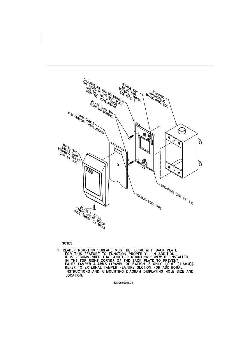
External tamper feature
The Model 94x/97x Readers are also equipped with an external
tamper feature. This feature can be activ ated by removi ng the key
on the backplate prior to mounting.
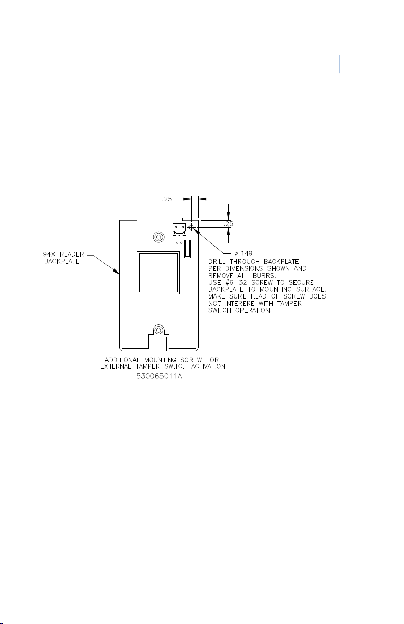
Model 94x only: Apply the mounting method as shown in
Figure 1, Recommended Addit ion al Mounti ng Instructions for
External Tamper Switch Activation to mounting instructions in
Figure 2, "Model 940 Reader - Gang Box Mounting" Figure 3,
"Model 940 Reader - Direct Wall Mounting" Figure 4, "Model
941 Reader - Gang Box Mounting" and Figure 5, "Model 941
Reader - Direct Wall Mounting" if you are using the external
tamper feature.
Note: In order for this feature to work properly, the reader mounting
surface must be flush with the backplate.

Model 94x/97x Proximity Reader
10
Installation Manual
Mounting diagrams
The figures listed below begin on the next page. Refer to the
appropriate figure for the type of reader you are mounting.
• Figure 1, Recommended Additional Mounting
Instructions for External Tamper Switch Activation
• Figure 2, “Model 9 40 Reader - Gang Box Mounti ng,” on
page 12.
• Figure 3, “Model 940 Reader - Direct Wall Mounting,”
on page 13.
• Figure 4, “Model 9 41 Reader - Gang Box Mounti ng,” on
page 14.
• Figure 5, “Model 941 Reader - Direct Wall Mounting,”
on page 15.
• Figure 6, “Model 970/972 Reader - Gang Box
Mounting,” on page 16.
• Figure 7, “Model 970/972 Reader - Direct Wall
Mounting,” on page 17.
• Figure 8, “Model 971/973 Reader - Gang Box
Mounting,” on page 18.
• Figure 9, “Model 971/973 Reader - Direct Wall
Mounting,” on page 19.
Mounting the reader 11
Figure 1. Recommended Additional Mounting Instructions for External Tamper Switch
Activation
Model 94x/97x Proximity Reader
12
Installation Manual
Figure 2. Model 940 Reader - Gang Box Mounting

Figure 3. Model 940 Reader - Direct Wall Mounting
Mounting the reader 13

Model 94x/97x Proximity Reader
14
Installation Manual
Figure 4. Model 941 Reader - Gang Box Mounting

Figure 5. Model 941 Reader - Direct Wall Mounting
Mounting the reader 15

Model 94x/97x Proximity Reader
16
Installation Manual
Figure 6. Model 970/972 Reader - Gang Box Mounting

Figure 7. Model 970/972 Reader - Direct Wall Mounting
Mounting the reader 17

Model 94x/97x Proximity Reader
18
Installation Manual
Figure 8. Model 971/973 Reader - Gang Box Mounting

Figure 9. Model 971/973 Reader - Direct Wall Mounting
Mounting the reader 19

Model 94x/97x Proximity Reader
20
Installation Manual
Configuring the reader
Switch settings
T w o banks of f our DIP swi tches l ocate d on the bac k of the r eader
are used to select the reader power level, operating mode, and
beeper sound level. Please note that the location and orientation
of switch block SW2 have changed for readers manufactured
after December , 2002 as il lustrat ed in Figure 10, “Model 94x/97x
Reader, J1 Connector and DIP Switch Locations (PCB Assembly
P/N 100079002 manufactured 12/02 or later),” on page 22.
CAUTION: Power should be removed from the reader while switch
Selecting reader power level
settings are changed.
The reader’s power requirement is selected using four DIP
switches. The optimum power level will vary with each
installation. Higher power levels give improved read range for
badges, while lower power levels allow greater cabling distance
between the reader and the microcontroller. A detailed
explanation is provid ed below. The figures on the next page show
the location of the DIP switches. Th e tables that follow the
figures give the switch settings along with the read ranges and
cable distances.
Explanation of Read Range/Cable Distance/Power Level:
Maximum badge read range is determined by the distance at
which the field transmitted by the reader is just strong enough to
wake up the badge. Therefore, the higher the reader’s
transmission power, the greater the badge read range will be. The
trade-off for increased read range is a decrease in the maximum
cabling distance between the reader and the microcontroller. The

Configuring the reader 21
trade-off between read range and cabling distance is common to
all proximity badge readers. The power selection switches on the
94x/97x readers allow the optimum power setting to be selected
to suit individual installations.
For example: On the high power setting, giving the greatest
badge read range, the reader typically requires 200mA of supply
current from the microcontroller. If there is 1,000 feet of 22AWG cable between the reader and the microcontroller, the total
reader power and power re turn path is 2,000 fe et. Since 22-AWG
cable has a typical resistance of 16 ohms per 1,000 feet, the total
resistance in the reader’s power and pow er return wire is 32
ohms. By Ohms Law (V=IR), it follows that the total voltage
dropped in the reader power and power return wires will be 6.4V
(6.4V = 200mA x 32 Ohms). Therefore, the reader sup ply voltage
will drop from 12V at the microcontr oller t o 5.6V (12V - 6.4 V) at
the reader. Such a supply voltage is too low for the reader to
function reliably.
If the low power setting is selected, the badge read range is
reduced. However, the reader now typically requires only 75mA
of supply current; therefore, the voltage drop in the power and
power return wires is much less. In this case, the reader supply
voltage will only be reduced to 9.6V; high enough for reliable
operation.

Model 94x/97x Proximity Reader
1
2
3
4
OFF
ON
SW2
22
Installation Manual
Figure 10. Model 94x/97x Reader, J1 Connector and DIP Switch Locations
(PCB Assembly P/N 100079002 manufactured 12/02 or later)

Configuring the reader 23
4
3
2
1
ON
OFF
SW2
Figure 11. (PCB Assembly P/N 100079001 manufactured prior to 12/02)
CAUTION: Power should be removed from the reader while switch
settings are changed.

Model 94x/97x Proximity Reader
24
Installation Manual
The table below shows the switch settings for each of the three
power levels.
Table 1. Power level switch settings
Power Level Switch 1 Switch 2 Switch 3 Switch 4
LOW OFF ON ON OFF
MEDIUM ON OFF OFF ON
HIGH ON ON ON ON
The table below gives the read ranges for each of the readers
based on the power level settings. All read ranges are typical
maximums.
Table 2. Read range by model number
Power level 97x 94x
LOW 5 in
127 mm
MEDIUM 6 in
152 mm
HIGH 7 in
178 mm
in = inches
mm = millimeters
4 in
102 mm
5 in
127 mm
6 in
152 mm

Configuring the reader 25
The table below gives the maximum cabling distances between
the reader and the microcontroller for each of the three power
levels.
Table 3. Cable distances
Power
level
LOW 5500 ft
MEDIUM 2200 ft
HIGH 600 ft
13.6 Volts (see Note 1) 12 Volts (see Note 1)
18 AWG 22 AWG 18 AWG 22 AWG
1676 m
671 m
183 m
Note:
1 Reader supply voltage measured at microcontroller:
13.6V is nominal when line powered, 12V is nominal
when battery powered.
2 Not recommended for 12V, battery-backed installations.
3 All cable distances are typical maximums.
4 Readers powered by a local 12 VDC power supply will
have a maximum cable distance of 5,500 feet (1676 m) of
22-AWG telephone wire for all power level settings.
2000 ft
610 m
900 ft
274 m
250 ft
76 m
3500 ft
1067 m
1100 ft
335 m
See Note 2 See Note 2
1500 ft
457 m
450 ft
137 m

Model 94x/97x Proximity Reader
26
Installation Manual
Selecting operating mode
Field changeable DIP switches allow all 94x and 97x readers to
operate in one of four distin ct opera ti ng modes : Wiegand (4001),
F/2F, Supervised, and Silent Supervised.
In the unsupervised modes, the reader communicates with the
microcontroller over a unidirectional Wiegand or F/2F data link
that carries badge data only.
In the supervised modes, the reader communicates with the
microcontroller over a bidirectional F/2F data link, that carries
badge data, supervision messages, exit request and door switch
status, and microcontroller acknowledgments and commands.
Silent Supervised mode
is ideal for inst allati ons where no aud ible
or visual indication of communication loss with the
microcontroller is desired at the reader.
The table below shows the DIP switch settings for each of the
four operating modes.
Table 4. Operating mode DIP switch settings
Operating mode Switch 5 Switch 6
Wiegand
F/2F
Supervised F/2Fb
Silent supervised F/2Fb
a. ProxLite badge data is sent using 40-bit (4001) Wiegand format . Keyboard
b. All ProxLite badge data is sent using a 12-digit F/2F format .
a
b
information is sent using 8-bit Wiegand format .
OFF OFF
ON OFF
OFF ON
ON ON

Configuring the reader 27
Selecting beeper sound level
The table below shows the DIP switch settings for the three
beeper sound levels.
Table 5. Beeper sound level DIP switch settings
Beeper sound level Switch 7 Switch 8
Normal ON ON
Low ON OFF
Off OFF ON

Model 94x/97x Proximity Reader
28
Installation Manual
Connecting the reader
For pinout and wiring information, refer to the following:
• Pinouts on page 28
• Wiring diagrams on page 29
Note: To maintain CE compliance, shielded cable and connections must
be used as shown in the section, “CE/FCC compliance” on page 46.
Pinouts
The table below shows the pinouts for connecting the reader to
the microcontroller. Connector J1, pin 1 is to the right as you
view the connector from behind the reader. See Figure 10 on
page 22 and Figure 11 on page 23.
Table 6. Pinouts
Connector: J1
Pin number
Signal Pigtail Wire Color
1+12 VDC Red
2 Ground Black
3 Red LED External Drive Blue
4 Green LED External Drive Brown
5 Yellow LED External Drive Orange
6 Reader Data 0 Green
7 Reader Data 1 White
8 Beeper External Drive Violet
9Keying Pin
10 Door DI (Door Contact Switch) Yellow
11 Exit DI (Exit Request Button) Gray

Connecting the reader 29
Wiring diagrams
See the wiring diagrams that follow for details on connecting the
reader to the microcontroller based on the mode of the reader.
• Figure 12, “Wiring diagram, Model 94x/97x Supervised
F/2F Mode,” on page 30.
• Figure 13, “Wiring diagram, Model 94x/97x
Unsupervised F/2F Mode,” on page 32.
• Figure 14, “Wiring diagram, Model 94x/97x
Unsupervised Wiegand Mode,” on page 34.

Model 94x/97x Proximity Reader
30
Installation Manual
Figure 12. Wiring diagram, Model 94x/97x Supervised F/2F Mode

Connecting the reader 31
Note: (Unless otherwise specified):
1 For Micro/2/4/5 only: a 470 ohm, 1/2W, pull-up resistor is required between +12 VDC and
READER DATA 1. The pull-up resistor should be installed at the microcontroller’s terminal block.
Resistors are supplied with the reader.
2 Shielded cable is recommended in electrically noisy environments.
3 If using shielded cable, connect all shields together at the microcontroller end. Connect to the
ground stud in the lower left corner of Micro/2/4/5 cabinets using 14-AWG wire. No shield
connections at the reader.
4 If using a local power supply, do not connect +12V line from the microcontroller to the reader.
However, the negative side of the power supply must be connected to the microcontroller
(pin 2 on the reader port). Keep the wiring from power supply to reader less than 50 feet.
5 Switching the external indicator drives to GND activates the indicator. High impedance or +12V
deactivates indicators. These drives may also be connected to user supplied, external
indicating circuitry.
6 Refer to the appropriate system manual to determine whether this connection is required for
door switch operation.
7 Blocking diodes may be 1N5817 or GE part number 521224001 (included with reader). The
diode must be installed in a secure location, not accessible through the reader removal.
8 Protection diodes may be 1N4002, 1N4003, or 1N4004 (installer supplied) for the door strike
assembly.
9 Fuse, power supply, door strike, and relay are provided by the installer.
10 If the door contact switch is not used, link reader pin 10 to pin 2.
11 Request to exit (REX) terminals on the reader are not to be connected for UL listed installations.

Model 94x/97x Proximity Reader
32
Installation Manual
Figure 13. Wiring diagram, Model 94x/97x Unsupervised F/2F Mode

Connecting the reader 33
Note: (Unless otherwise specified):
1 For Micro/2/4/5 only: a 470 ohm, 1/2W, pull-up resistor is required between +12 VDC and
READER DATA 1. The pull-up resistor should be installed at the microcontroller’s terminal
block. Resistors are supplied with the reader.
2 Shielded cable is recommended in electrically noisy environments.
3 If using shielded cable, connect all shields together at the microcontroller end. Connect to
the ground stud in the lower left corner of Micro/2/4/5 cabinets using 14-AWG wire. No
shield connections at the reader.
4 If using a local power supply, do not connect +12V line from the microcontroller to the
reader. However, the negative side of the power supply must be connected to the
microcontroller (pin 2 on the reader port). Keep the wiring from power supply to reader less
than 50 feet.
5 Switching the external indicator drives to GND activates the indicator. High impedance or
+12V deactivates indicators. These drives may also be connected to user supplied, external
indicator driving circuitry.
6 Refer to the appropriate system manual for specific wiring details.
7 Blocking diodes may be 1N5817 or GE part number 521224001 (included with reader). The
diode must be installed in a secure location, not accessible through the reader removal.
8 Protection diodes may be 1N4002, 1N4003, or 1N4004 (installer supplied) for the door
strike assembly.
9 Fuse, power supply, door strike, and relay are provided by the installer.
10 Request to exit (REX) terminals on the reader are not to be connected for UL listed
installations.

Model 94x/97x Proximity Reader
34
Installation Manual
Figure 14. Wiring diagram, Model 94x/97x Unsupervised Wiegand Mode

Connecting the reader 35
Note: (Unless otherwise specified):
1 For Micro/2/4/5 only: two 470 ohm, 1/2W, pull-up resistors are required; one between +12
VDC and READER DATA 1, the other between +12 VDC and READER DATA 0. The pull-up
resistors should be installed at the microcontroller’s terminal block. Resistors are supplied
with the reader.
2 Shielded cable is required. Belden 8725 wire is recommended. Do not pair DATA 1 and DATA 0.
3 If using shielded cable, connect all shields together at the microcontroller end. Connect to the
ground stud in the lower left corner of Micro/2/4/5 cabinets using 14-AWG wire. No shield
connections at the reader.
4 If using a local power supply, do not connect +12V line from the microcontroller to the reader.
However, the negative side of the power supply must be connected to the microcontroller
(pin 2 on the reader port). Keep the wiring from power supply to reader less than 50 feet.
5 Switching the external indicator drives to GND activates the indicator. High impedance or
+12V deactivates indicators. These drives may also be connected to user supplied, external
indicator driving circuitry.
6 Refer to the appropriate system manual for specific wiring details.
7 Blocking diodes may be 1N5817 or GE part number 521224001 (included with reader). The
diode must be installed in a secure location, not accessible through the reader removal.
8 Protection diodes may be 1N4002, 1N4003, or 1N4004 (installer supplied) for the door strike
assembly.
9 Fuse, power supply, door strike, and relay are provided by the installer.
10 Request to exit (REX) terminals on the reader are not to be connected for UL listed
installations.

Model 94x/97x Proximity Reader
36
Installation Manual
Testing the reader
Follow the steps below to verify that the reader is working
correctly.
1. Check all cabling and electrical connections from the
reader to the microcontroller. Refer to the wiring
diagrams on page 30, page 32, and page 34.
2. Verify that the microcontroller is properly configured.
Refer to the appropriate GE microcontroller manual.
3. Verify that the reader switches are properly set for the
power setting, cabling type, distance, and desired mode
of operation. See “Switch settings” on page 20.
4. Apply power to the reader and verify that the yellow
LED is on. You may want to use a multimeter to test the
voltage at the reader’s pigtail connector J1, using ground
(pin 2) as a reference. The power pin (pin 1), data lines
(pins 6 and 7) and door DO (pin 4) should all read
approximately 12V.
5. Check that the proper version of firmware is installed in
the microcontroller. Refer to the appropriate
microcontroller manual.
6. Close the tamper swit ch by joining the reader and
backplate.
Note: If external tamper is activated, make sure the reader
backplate mounting surface is flush with backplate.
When all wires are connected to the reader, ensure that
the supervision function is operating properly (if a
supervised mode is sel ected ), by ver ifyin g that t he reade r
is not sounding a short triple beep every 30 seconds, and
the red LED is not flashing slowly (every 2 seconds). If

Testing the reader 37
such an alarm is present, refer to the troubleshooting
guide at the end of this manual.
Note: In silent supervised mode, no indication of loss of
supervision is provided, except badges will not be read.
7. Select a known good ProxLite test badge. Be sure the
badge is properly entered in the host syste m, and the
micro badge data format matches the rea der. If the reader
is used with a keypad (Models 972 and 973 only) , assi gn
a proper PIN.
8. Check that the door is secure. Present the badge to the
reader. Observe that the reader beeps briefly and the
yellow LED blinks off.
9. If the reader is used with a keypad (Models 972 and 973
only), enter a PIN. Refer to the host manual for
instructions on entering the PIN. Observe that the green
LED turns on indicating a valid access has been granted
by the host.
10. Open the door. This verifies that the door strike operates
correctly.

Model 94x/97x Proximity Reader
38
Installation Manual
Troubleshooting the reader
If the operation of a component is in doubt, substitute a known
good component and retry the system. Always verify wiring
against wiring diagrams before powering up the system.
The troubleshooti ng guide is divided int o thre e sect ions. The firs t
section is applicable to all installations, the second section
provides additional diagnosis for unsupervised readers, and the
last section provides additional diagnosis for supervised readers.
All installations
All LEDs are on and the beeper is on (if enabled): Usually, an
indication that the rea der’s vol tage is too low. This may be caused
if the wrong reader voltage is selected at the microcontroller or
the cable is too long between the reader and the microcontroller.
1. Measure the reade r supp ly volta ge at the mi crocont roll er.
It should read between 12 and 15 VDC. If the voltage is
correct, continue to step 2 below. If the voltage is
incorrect, refe r to the ap propriat e micro controll er manual
and correct the voltage.
2. Set the reader to low power mode if the cable distance is
too long (See Table 1 “Power level switch settings,” on
page 24). This may correct the problem.
3. If the problem is still present, while in low power mode,
measure the voltage betwe en J1 p in 1 (power) and J1 pin
2 (ground). This voltage should be greater than 8 VDC
and less than or equal to the reader supply voltage. If the
voltage is too low, correct the wiring. If the voltage is
correct, replace the reader.

Troubleshooting the reader 39
None of the LEDs are on: Check that the beeper is enabled (See
Table 5 “Beeper sound level DIP switch settings,” on page 27),
then present a known good ProxLite test badge to the reader
while listening for the beeper.
If the beeper sounds, the reader is faulty and should be replaced.
If the beeper does not sound, check the power connections to the
reader and check the reader supply voltage at connector J1 pin 1.
The green LED is always on: The green LED indicates that the
door strike is open. It is controlled by the input on connector J1
pin 4.
1. Disconnect the wire on J1 pin 4. If the green LED stays
on, the reader is faulty and should be replaced. If the
green LED goes of f the n the pro blem is mos t likel y not in
the reader.
2. Reconnect the wire on J1 pin 4 and measure the voltage
at J1 pin 4. Low voltage turns on the green LED. If the
voltage is low, check to see if the host system is turning
on the door strike.
The beeper doesn’t sound and the yellow LED doesn’t blink
when a badge is presented to the reader OR the badge read
range is very poor:
When the beeper sounds and t he y ell ow LED
blinks off, it indicates that a badge has been read and its data sent
to the microcontroller.
Note: The beeper will not sound if it has been disabled. (See Table 5
“Beeper sound level DIP switch settings,” on page 27
.)
1. Models 941, 971 and 9 73: Check that th e metal b ackplate
is installed correctly. See the appropriate installation
drawing in this manual for details.
All other models: Be sure they are not mounted on or
near a metal w all or large metal object.

Model 94x/97x Proximity Reader
40
Installation Manual
2. Check that the reader is not mounted within 3 feet
(1 meter) of a computer terminal or within 10 inches
(250 mm) of another proximity reader. The only
exception to this 10-inch (250 mm) limit is for 941, 971,
and 973 readers inst alled wi th th e optiona l, back-t o-back,
metal mounting plates.
3. Present a test ba dge ( kno wn to be working) to the reader.
If the beeper and yellow LED still fail to indicate a valid
badge read and se nd, re place th e rea der wit h a r eader that
you know is working correctly. If this corrects the
problem, the original reader is faulty and should be
replaced. If this does not correct the problem, the badge
is probably defective.
The door does not open and the green LED does not turn on
when a badge is presented:
1. Verify that the badge an d reade r are proper ly ent ered i nto
the system.
2. Verify that the door strike and the green LED are wired
correctly. Since the green LED and the door strike are
separate indicators, this problem is not an indication of a
defective reader.
The green LED does not turn on, but the door strike unlocks
the door when a valid badge is presented:
1. Verify that the door DO is wired correctly. Refer to the
appropriate wiring diagram.
2. Disconnect the wire from J1 pin 4 (green LED) and
connect J1 pin 4 to J1 pin 2 (gro und). If the gree n LED is
now on, the reader is good and the connection to the
reader is defective. If the green LED does not turn on,
replace the reader.

Troubleshooting the reader 41
Green LED turns on but the door does not open: Verify correct
door strike wiring and operation. The reader is functioning
properly.
The beeper is always on and/or the yellow LED is off: The
yellow LED blinks off and the beeper sounds while a key is
pressed (Models 972 and 973 only), as long as the reader DIP
switches are not set to disable the beeper.
False or intermittent tamper alarm s: Ver ify that the reader
mounting surface is flush with the backplate. If you continue to
experience proble ms with tamper operatio n, clean the contacts on
the PC board as well as the contact fingers on the backplate.
Unsupervised modes only
The reader sounds a short triple beep every 30 seconds and the
red LED flashes quickly (every 400 ms):
violation. Verify that the r eader hous ing is prope rly secur ed to the
backplate. If an external tamper is used, review the appropriate
recommended mounting instructions. If the reader is secure and
mounted properly, then the reader is faulty and should be
replaced.
Indicates a tamper
Supervised modes only
Reader sounds a short triple beep every 30 seconds and the red
LED flashes slowly (every 2 seconds):
communication with the microcontroller.
1. Check the reader to microcontroller wiring. Refer to the
appropriate instal lation drawing. Verify that the AUX DO
is jumpered to the READER DATA 1 on the
microcontroller.
The reader has lost

Model 94x/97x Proximity Reader
42
Installation Manual
2. Verify that the correct pull-up resistor is installed on the
microcontroller. See Figure 12, “W iri ng diagram, Model
94x/97x Supervised F/2F Mode,” on page 30.
3. Verify that the microcontroller has the correct firmware
for a supervised reader. Refer to the manual that came
with your microcontroller for instructions.
4. Try the reader on a different reader input of the
microcontroller. If this corrects the problem, then the
microcontroller is probably causing the problem.
5. Replace the reader with one you know is working
correctly. If this corrects the problem, then the reader is
probably faulty and should be replaced.
6. If none of the above steps have identified the problem,
there may be a significant noise source present in the
installation that is interfering with the reader-tomicrocontroller communications. If this is the case, use
shielded wire for reader-to-microcontroller connections.
The beeper sounds and the yellow LED blinks off more than
once when a valid badge is presented:
The beeper sounds and
the yellow LED blinks off every time badge data is sent to the
microcontroller. When a badge is presented to the reader, data is
transmitted from the badge to the reader. The reader interprets
and checks the data received to make sure it has not been
corrupted. The reader then sends the data to the microcontroller
and waits approximately 1/3 of a second for the microcontroller
to acknowledge re ceipt. If no ackn owledge is receiv ed during this
time, the reader resends the data causing the beeper to sound
again and the LED to blink off. After the third unacknowledged
attempt, the reader stops trying and indicates a communications
error. This feature is useful in troubleshooting marginal
installations where a high level of electrical noise may cause the
reader to mak e multiple at tempts at communications.

Troubleshooting the reader 43
1. If multiple beeps occu r regularly, refer to the i nstallation
drawings to verify that the correct pull-up resistor has
been added to the microcontroller.
2. Replace the reader with one you know is working
correctly. If this solves the problem, t he o rigin al rea der i s
probably faulty and should be replaced. If the problem
persists, use shielded cable between the microcontroller
and the reader.
The reader sounds a short triple beep every 30 seconds and the
red LED flashes quickly (every 400 ms):
Indicates a tamper
violation. Verify that the r eader hous ing is prope rly secur ed to the
backplate. If an external tamper is used, review the appropriate
recommended mounting instructions. If the reader is secure and
mounted properly, then the reader is faulty and should be
replaced.
The beeper and/or red LED are always on: The microcontroller
may command the reader to turn on the red LED and the beeper
as long as the reader DIP switches are not set to disable the
beeper. If the door status switch input at J1 pin 10 is not tied to
ground, the reader informs the system that the door is open. The
system may then activate the alarm at the reader. If this is not the
problem, then the system software probably told the reader to
activate its alarm. Refer to the appropriate system manual for
conditions that cause the software to activate the alarm. If it
appears that no such system command is active, replace the
reader with one you know works correctly. If this solves the
problem, the original reader is faulty and should be replaced.
The green LED flashes quickly (every 400 ms): This indicates
that the microcontroller has requested a PIN entry on a Model
972 or 973 Reader with a keypad. For all other models, chec k the
reader configuration on your system to be sure a keypad reader
was not selected.

Model 94x/97x Proximity Reader
UL Listed Installations
44
Installation Manual
Regulatory approvals
UL
Specifications for UL compliance are shown below:
• Operating Temperature Range: +32 F (+0 C) to +120 F
(+49 C)
• Relative H umidity: 85%
• The Model 94x/97x readers were evaluated by UL for
indoor use only.

CE
Manufacturers
Declaration of Conformity
For
Product Identification:
Model/type: 430084001/2, 430084501/502 BOM revision level:940=Q; 941=P
(Model 94X) 970=Q, 971=P, 972=Q,
430085001/2, 430085501/502, 973=P
430088001/2, 430088501/502
(Model 97X)
Category (description): Proximity Reader
Brand: GE Security
Manufacturer: GE Security B.V. GE Security GE Security
Kelvinstraat 7 1510 Tate Blvd Suite 100
6003 DH Weert Hickory, NC 28511 791 Park of Commerce Blvd.
The Netherlands USA Boca Raton, Florida 33487
USA
EU Representative: GE Security B.V.
Kelvinstraat 7
6003 DH Weert
The Netherlands
Equipment class identifier (RF products falling under the scope of R&TTE)
Means of Conformity:
We declare under our sole responsibility that this product is in conformity with Directive 93/68/EEC
(Marking) and/or complies with the essential requirements and all other relevant provisions of the
1999/5/EC (R&TTE) based on test results using (non)harmonized standards in accordance with the
Directives mentioned.
Concerning R&TTE
EMC Safety Radio
A sample of the
product has been
tested by:
PSE
12955 Bellamy
Brothers Blvd.
Dade City, FL 33525
PSE
12955 Bellamy
Brothers Blvd.
Dade City, FL 33525
PSE
12955 Bellamy
Brothers Blvd.
Dade City, FL 33525
Test report reference 07F256I 02P351/ 02P352 02F351C/ 02F352C
Applied standards EN50130-4(1995)
+A1(1998) +A2(2003)
EN60950-1 (2001) EN300-330 v1.3.1
(2001/2006)
Not Applicable None (class 1 product) (class 2 product)
x
Regulatory approvals 45

Model 94x/97x Proximity Reader
O
46
Installation Manual
CE/FCC compliance
To make the Model 94x/97x reader installation CE and FCC
compliant, the cable connecting the reader to the microcontroller
must have its shield g rounded at the microc ontrolle r , accor ding to
one of the methods specified in the figures below.
Note: Do not make shielded connections at the reader.
Figure 15. Typical installation (Internal to the micro)
Using shielded cable/drain wire
Figure 16. Typical installation (External to the micro)
Using shielded cable/drain wire

Transition
Series
i

GE
Security
U.S.
T 888 GE SECURITY (1 888 437 3287)
F 561 998 6224
Asia
T 852 2907 8108
F 852 2142 5063
Australia
T 61 3 9259 4700
F 61 3 9259 4799
Europe
T 32 2 725 11 20
F 32 2 721 86-13
Latin America
T 305 593 4301
F 305 267 4300
www.gesecurity.com
© 2008 General Electric Company
All Rights Reserved.
460157001P/01-08
 Loading...