

Page 1
T-700, T-720, and T-725 Readers
Installation Sheet
Description
The T-700, T-720, and T-725 Smart Card Readers
support 13.56 MHz Mifare (ISO 14443, Type A) Classic
1k and 4k, Vicinity (ISO 15693), HID iClass, and FIPS
201 (PIV) [3] credential technologies. The readers are
capable of reading encoded data from the secure sector
of the Mifare credentials. The reader output is either
Wiegand or RS-485 communication.
For secure credentials, the readers encrypt
communication between a smartcard and the reader
using either diversified or secured keys. The reader
compares user information with the information stored
on the card.
Verify contents
Inspect the package and contents for visible damage. If
any components are damaged or missing, do not use
the unit; contact the supplier immediately. If you need to
return the unit, you must ship it in the original box.
The package should include the following contents:
• Electronic assembly
• Cover
• Mounting base
• T-700, T-720, and T-725 Readers Installation Sheet
(this document)
• Hardware mounting kit
• Mounting hole template
• Cable (pigtail) assembly (models 720 and 725 only)
Credential default read settings
The readers support the following credentials:
Table 1: Supported credentials
Name Type Size RF Technology Default Output
Diversified GE keys Mifare 1k, 4k ISO 14443 ON 26 bit or 55 bit
OESM fixed keys Mifare 1k, 4k ISO 14443 OFF 26 bit or 55 bit
Diversified GE keys My-D 10 kBits ISO 15693 ON 26 bit or 55 bit
FIPS 201 / PIV[3] US Government* All Type A / Type B OFF 75 bit or 200 bit (GSA defined)
UID only HID iClass** 2k 13.56 MHz ON 55 bit
UID only Vicinity (non My-D)** All ISO 15693 ON 55 bit
UID only DESFire** All ISO 14443 ON 40 bit
* Pending certification and release.
When enabled, ISO 14443 UID read is disabled.
** When in T-5xx emulation mode, enabled by the command card.
1 of 4 P/N 460975001C • ISS 18NOV10
Page 2
Communication protocol
The reader supports Open Supervised Device protocol
(OSDP) for RS-485 communication.
When using Wiegand communication, the output is in
the format encoded on the cards. When using PIV, the
Wiegand output can be configured to either 75-bit or
200-bit [3].
Installation
All reader models can be mounted on a single-gang
electrical box or directly on the wall. The T-700
requires an additional mounting plate that must be
ordered separately when mounting on a single-gang
box. The T-720/725 readers can also be mounted on a
2-gang electrical box.
1. Find a suitable mounting location for the reader on
the wall or doorframe.
2. If mounting directly on the wall, perform the
following:
Table 3: RS-485 address selection
ddress Switch 4 Switch 5 Switch 6 Switch 7 Switch 8
A
00 0 0 0 0 0
01 0 0 0 0 1
02 0 0 0 1 0
03 0 0 0 1 1
04 0 0 1 0 0
05 0 0 1 0 1
••• ••• ••• ••• ••• •••
30 1 1 1 1 0
31 1 1 1 1 1
0 = OFF, 1 = ON
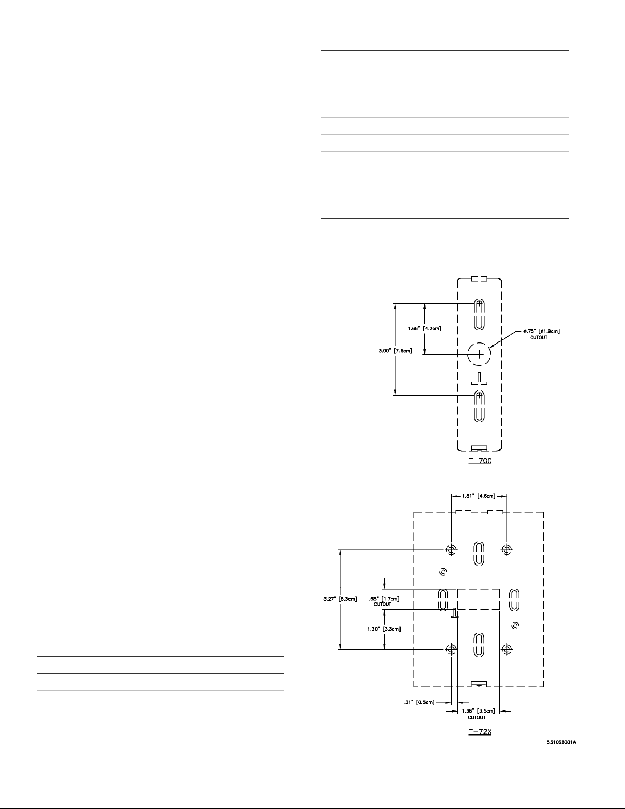
Figure 1: Mounting template
T-700 reader: Drill the properly sized and spaced
mounting holes according to the dimensions
shown in Figure 1. Drill one 0.75 in. (1.9 cm)
diamete
r hole for the reader cable.
T-720/725 readers: Drill properly sized and
spaced mounting holes according to the
dimensions shown in Figure 1. Drill one 1.38 in.
(3.5 cm
) x 0.68 in. (1.7 cm) rectangular cutout for
the reader cable.
3. Mount the base to the wall or doorframe using #6
(3.5 mm) screws or larger.
4. Wire the reader cable to the panel cable in
accordance with procedures specified in “Wiring”
on page 3.
5.
Set the DIP switches to the appropriate setting for
your configuration. See Table 2 and Table 3.
6.
Secure the case and cover onto the base using
the #6 security screw provided. See Figure 2 and
Figure 3.
Table 2: DIP switch settings
Switch Function Setting
1 Termination for Y – Z Default = OFF = No termination
2 Termination for A – B Default = OFF = No termination
3 Half/full-duplex select Default = OFF = full duplex
2 of 4 P/N 460975001C • ISS 18NOV10
Page 3

Figure 2:
Figure 3: T-72x reader installation
T-700 reader installation
Wiring
The T-700 reader is supplied with a fixed 12 conductor
pigtail and the T-720 and T-725 are supplied with a
pluggable 12 conductor pigtail.
The voltage specifications for these readers is 10-16
VDC, although 12 VDC or greater is recommended for
better performance and cable run distances.
To wire the readers:
1. Use the cable connection table below to connect
the pigtail to the panel cable. Match the pigtail
colors to the correct panel cable signal wires.
2. Provide a DC power source of 10-16 VDC.
3. Verify the reader is properly grounded by
connecting the reader drain wire to the panel.
Refer to the panel installation manual for
connection details.
Table 4: Wiring connections
Mode
Color Wiegand RS485 HD
(2-wire)
Red 10 to 16 VDC 10 to 16 VDC 10 to 16 VDC
Black Ground Ground Ground
Green Data 0 Not used Receive +
White Data 1 Not used Receive −
Orange Green LED
control
Brown Red LED
control
Yellow Beeper control Beeper control Beeper control
Gray Not used Not used Not used
Pink Card present Transmit/receive + Transmit +
Tan Tamper Transmit/receive − Transmit −
Blue Not used Not used Not used
Purple Not used Not used Not used
Green LED control Green LED
Red LED control Red LED control
RS485 FD
(4-wire)
control
P/N 460975001C • ISS 18NOV10 3 of 4
Page 4

Configuration cards
The following predefined configurations cards are available from
UTC Fire & Security to assist you in setting up the listed functions
for your reader.
Table 5: Predefined configuration cards (no customer input required)
Kit
part #
521305001 Beeper off Set beeper off
Reset configuration to
521306001 LED green normal Change LED colors
Reset configuration to
521307001[3] Select 75-bit PIV format Set PIV Wiegand format
Select 200-bit PIV
Disable PIV Disable PIV
Enable PIV Enable PIV
Reset configuration to
521308001 5xx emulation enable Read 13.56 MHz UID(s)
Reset configuration to
521309001 Keypad configuration to
Keypad configuration to
Configuration
card set
default
default
format
default
default
1 key, 8-bit complement
4-bit burst
Function
Reset configuration to
default
Reset configuration to
default
Set PIV Wiegand format
Reset configuration to
default
Reset configuration to
default
Sets keypad output to 1
key, 8-bit complement
Sets keypad output to 4bit burst
Specifications
Voltage 10 to 16 VDC
Power supply Linear DC recommended
Cable distance from
reader to panel
Read range [1] Model T-700, T-720, and T-725
Wiegand output Mifare 5502 (55-bit)
Tamper output Open collector
Credential technologies Mifare (Secure) Classic 1k and 4k
Operating environment [2]
Temperature
Humidity
200 ft. max. 22 AWG
300 ft. max. 20 AWG
500 ft. max. 18 AWG
• Mifare up to 1 in. (2.54cm)
• Ultralight cards not supported
• Vicinity up to 2 in. (5.08cm)
Vicinity 5502 (55-bit)
My-d (Secure) 10k
FIPS 201 (PIV) [3]
ISO 14443 Level 2 (UID only)
ISO 15693 (UID only for non My-d)
-31°F to +149°F [-35°C to +65°C]
0 to 93% RH, noncondensing at 90°F
(32°C)
Compatible electrical
boxes
Colors Black, charcoal, and gray
Regulatory ETL 294, UL 294, CE and FCC Part 15
ISO standards Mifare ISO 14443A
GSA standard FIPS 201 (PIV) [3]
Regulatory evaluation
Power consumption Average: less than 105 mA at 12 VDC
UL evaluation for UL listed installations:
[1] Model T-700, T-720,
and T-725 read range:
[2] Operating environment:
Temperature
Humidity
[3] FIPS/PIV mode not
evaluated by UL
T-700 readers:
North American single-gang box (with
additional mounting plate – ordered
separately)
T-720/725 readers:
North American single-gang box
North American 2-gang box
Vicinity ISO 15693
Peak: less than 260 mA at 12 VDC
Mifare up to 1 in. (2.54cm)
Ultralight cards not supported
Vicinity up to 2 in. (5.08cm)
−25 to 120°F (−31 to 49°C)
0 to 85% RH, noncondensing
Certification and compliance
Certification
N413
European Union directives
2002/96/EC (WEEE directive): Products marked with
this symbol cannot be disposed of as unsorted
municipal waste in the European Union. For proper
recycling, return this product to your local supplier
upon the purchase of equivalent new equipment, or
dispose of it at designated collection points. For more
information see: www.recyclethis.info.
Contacting customer support
You can reach customer support by phone from 8 a.m.
to 8 p.m. EST, Monday through Friday.
UTC Fire & Security
United States: 1-888-437-3287
Asia: 852-2907-8108
Australia: 61-3-9239-1200
Canada: 800-267-6317
Europe: 32-2-725-11-20
Latin America: 305-593-4301
utcfireandsecurity.com
© 2010 UTC Fire & Security. All rights reserved.
GE and the GE monogram are trademarks of the General Electric
Company and are under license to UTC Fire & Security, 9 Farm
Springs Road, Farmington, CT 06034-4065
4 of 4 P/N 460975001C • ISS 18NOV10
 Loading...