

Page 1
Revision 4
Author: Anders Zellén
Wireless Solution Sweden Sales AB
Stureparksvägen 7 – 451 55 Uddevalla – Sweden
+46 522 511 511 Tel. +46 522 440 885 Fax.
Wirelessdmx.com [email protected]
1(23)
14/11/2014
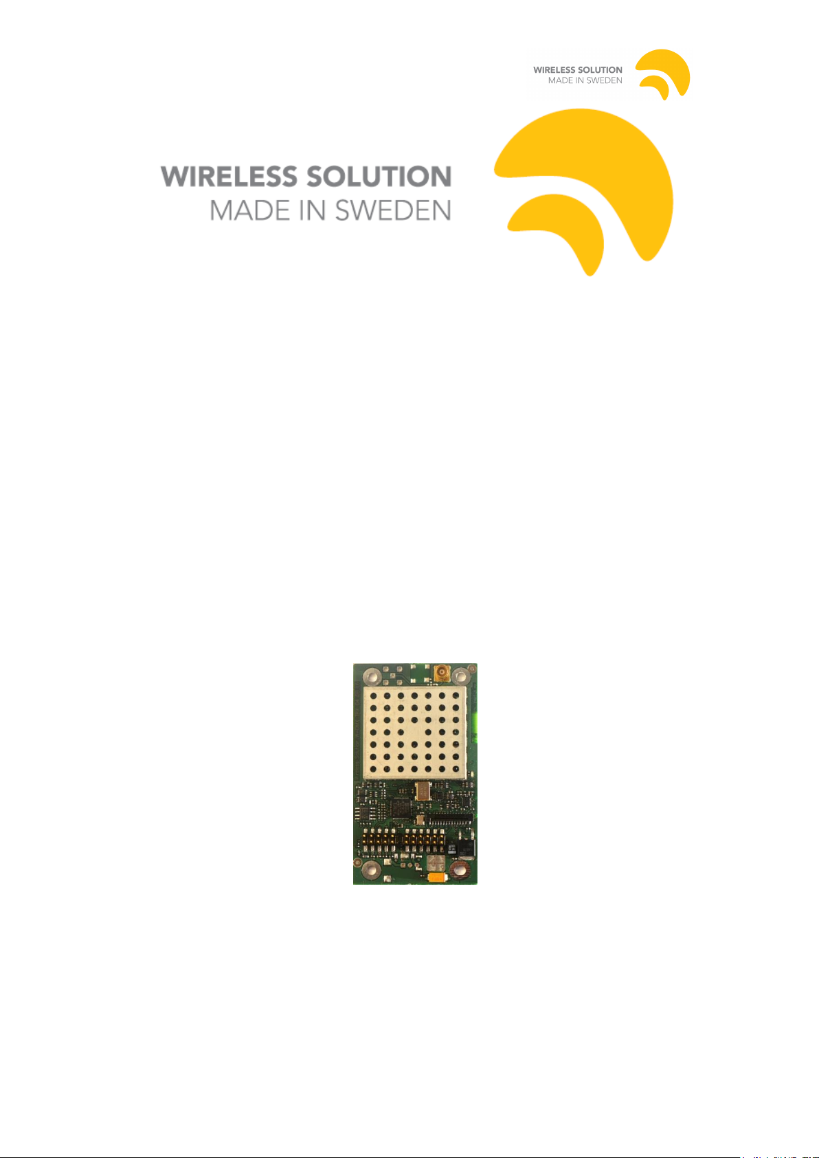
W-DMX TRX
IMPLEMENTATION GUIDE
L6 GENERATION 4S
REV. 4
Pro L6
Page 2

Revision 4
Author: Anders Zellén
Wireless Solution Sweden Sales AB
Stureparksvägen 7 – 451 55 Uddevalla – Sweden
+46 522 511 511 Tel. +46 522 440 885 Fax.
Wirelessdmx.com [email protected]
2(23)
14/11/2014
W-DMX TRX
Author: Anders Zellén
Date: 14/11/2014
Document revision: 4
Document Status: Company Confidential
This document describes the mechanical and electrical properties, as well as the
electrical interface, of the W-DMX TRX G4 Pro L6 card.
The W-DMX system is the most advanced wireless lighting control system on the
market today. With over 250,000 units sold, and over 45 OEM customers worldwide,
the W-DMX wireless protocol has become the world’s unofficial standard for
Wireless DMX and RDM control. The G4S line contains the following key features:
1. Support for Adaptive Frequency Hopping Spread Spectrum technology. This
technology allows the system to dynamically avoid other users of the radio
spectrum, in order to ensure that we do not cause interference with other radio
users i.e. WLAN. All radio cards come with this functionality as standard,
with zero-configuration required.
2. RDM support, with a full managed proxy implementation. All RDM devices,
when connected through the supporting W-DMX models will be exposed
through the system to an upstream controller automatically.
3. DataSafe and InvisiWire technologies, which collectively ensure that data is
more redundant to interference, and the system responds just as a wire would
respond.
This document is valid for L6 Pro hardware with G4S firmware.
Page 3

Revision 4
Author: Anders Zellén
Wireless Solution Sweden Sales AB
Stureparksvägen 7 – 451 55 Uddevalla – Sweden
+46 522 511 511 Tel. +46 522 440 885 Fax.
Wirelessdmx.com [email protected]
3(23)
14/11/2014
The W-DMX PCB is sensitive to ESD.
Follow proper ESD control procedures when
handling the W-DMX PCB.
CONFIDENTIALITY NOTICE
Any disclosure, copying, distribution or use of the contents of the information herein
without prior written authorization from Wireless Solution is prohibited.
Please refer to our Non-Disclosure Agreement for complete information about
Wireless Solution’s confidentiality and non-disclosure policies.
Warning ! ESD sensitive device
Page 4

Revision 4
Author: Anders Zellén
Wireless Solution Sweden Sales AB
Stureparksvägen 7 – 451 55 Uddevalla – Sweden
+46 522 511 511 Tel. +46 522 440 885 Fax.
Wirelessdmx.com [email protected]
4(23)
14/11/2014
Table of contents
Contents
1 STANDARDS COMPLIANCE ...................................................................................................... 6
1.1 FCC COMPLIANCE STATEMENT .................................................................................................. 6
1.2 USAGE OF THIS DEVICE ............................................................................................................... 6
1.3 USITT DMX-512 A COMPLIANCE ............................................................................................. 7
1.4 PRODUCT MARKING .................................................................................................................... 7
2 MECHANICAL DIMENSIONS ................................................................................................... 8
2.1 PRO L6 MODEL ............................................................................................................................ 8
3 ANTENNAS ................................................................................................................................... 8
4 POWER SUPPLY CONSIDERATIONS FOR RECEIVERS AND TRANSCEIVERS .............. 9
4.1 RECEIVERS .................................................................................................................................. 9
4.2 TRANSCEIVERS ........................................................................................................................... 9
4.3 POWER INDICATOR ..................................................................................................................... 9
5 INTERFACE CONNECTORS, J1 AND J3 .................................................................................. 9
5.1 CONNECTOR TYPES ..................................................................................................................... 9
5.2 PIN OUT FOR THE W-DMX PRO CARD ....................................................................................... 10
6 DMX INTERFACE AND SPECIFICATION............................................................................. 11
6.1 CONFORMITY TO ANSI E1.11-2008.......................................................................................... 11
6.1.1 §10.5.3 Loss of data handling procedure. ...................................................................... 11
6.1.2 §10.5.4 Packet processing latency. ................................................................................. 11
6.1.3 §10.5.5. NULL START Code functionality. ..................................................................... 12
6.1.4 §10.5.6 Slot footprint. ..................................................................................................... 12
7 USER INTERFACE .................................................................................................................... 12
7.1 FUNCTION SWITCH .................................................................................................................... 12
7.1.1 Link ................................................................................................................................. 12
7.1.2 Unlink ............................................................................................................................. 12
7.1.3 Transceiver direction ...................................................................................................... 12
7.1.4 Function Switch Timing .................................................................................................. 12
7.1.5 Status Indicator LED ...................................................................................................... 14
7.1.6 Mode Indicator LED, L6 only ......................................................................................... 15
7.2 LED OVERLAY INTERFACE, L6 ONLY ....................................................................................... 16
7.2.1 LED order ....................................................................................................................... 16
7.2.2 SPI Settings ..................................................................................................................... 16
7.3 W-DMX RDM INTERFACE ....................................................................................................... 17
8 IN SYSTEM SOFTWARE UPDATES (BOOT LOADER SUPPORT) ..................................... 17
8.1 DESIGN CONSIDERATIONS ......................................................................................................... 17
8.1.1 Bidirectional connection ................................................................................................. 17
8.1.2 A means of resetting the device ....................................................................................... 17
8.2 REFERENCE DESIGN .................................................... FEL! BOKMÄRKET ÄR INTE DEFINIERAT.
9 INSTALLATION GUIDELINES ................................................................................................ 18
10 SPECIFICATIONS ..................................................................................................................... 20
10.1 ELECTRICAL SPECIFICATIONS .............................................................................................. 20
ENVIRONMENTAL REQUIREMENTS ...................................................................................................... 21
APPENDIX 1. ORDERING CODES FOR RADIO CARDS ........................................................... 22
11 NOTES ......................................................................................................................................... 23
Page 5

Revision 4
Author: Anders Zellén
Wireless Solution Sweden Sales AB
Stureparksvägen 7 – 451 55 Uddevalla – Sweden
+46 522 511 511 Tel. +46 522 440 885 Fax.
Wirelessdmx.com [email protected]
5(23)
14/11/2014
Page 6

Revision 4
Author: Anders Zellén
Wireless Solution Sweden Sales AB
Stureparksvägen 7 – 451 55 Uddevalla – Sweden
+46 522 511 511 Tel. +46 522 440 885 Fax.
Wirelessdmx.com [email protected]
6(23)
14/11/2014
1 Standards Compliance
1.1 FCC Compliance Statement
This device complies with Part 15 of the FCC Rules.
Operation is subject to the following two conditions:
(1) this device may not cause harmful interference, and
(2) this device must accept any interference received, including interference that may cause undesired operation.
To assure continued compliance, any changes or modifications not expressly approved by the party responsible for
compliance could void the user's authority to operate this equipment.
NOTE: This equipment has been tested and found to comply with the limits for a Class B digital device, pursuant to
Part 15 of the FCC Rules. These limits are designed to provide reasonable protection against harmful interference in
a residential installation.
This equipment generates, uses, and can radiate radio frequency energy and, if not installed and used in accordance
with the instructions, may cause harmful interference to radio communications.
However, there is no guarantee that interference will not occur in a particular installation. If this equipment does
cause harmful interference to radio or television reception, which can be determined by turning the equipment off and
on, the user is encouraged to try and correct the interference by one or more of the following measures:
• Reorient or locate the receiving antenna.
• Increase the separation between the equipment and receiver.
• Connect the equipment into an outlet on a circuit different from that to which the receiver is connected.
• Consult the dealer or an experienced radio/TV technician for help.
When the device is installed in the carrier equipment, included label “Contains FCC ID: NY2-WDMXTRXDB” must be
fastened on product label on the bottom of the unit.
The module will be installed by Wireless Solution during production of host equipment or by Wireless
Solution trained service technicians.
RF Exposure Warning for North America
RF Exposure: This device complies with part 2.1091 of the FCC rules for an uncontrolled environment. This
equipment shall be installed and operated with a minimum distance of 20cm (7.9 in.) between the antenna and the
user.
1.2 Usage of this device
This device is certified to be used together with the following units and antennas from
Wireless Solution
Host products:
BlackBox F-1, A40001G4MK2-X
WhiteBox F-1, A40002G4-X
WhiteBox F-2, A40004G4-X
BlackBox F-2, A40005G4MK2-X
ProBox F-2500, A40007G4-X
WhiteBox R-512, A40101G4-X
BlackBox R-512, A40102G4MK2-X
Antennas:
A40511G4, omnidirectional antenna with 4.0dBi gain
Page 7

Revision 4
Author: Anders Zellén
Wireless Solution Sweden Sales AB
Stureparksvägen 7 – 451 55 Uddevalla – Sweden
+46 522 511 511 Tel. +46 522 440 885 Fax.
Wirelessdmx.com [email protected]
7(23)
14/11/2014
1.3 USITT DMX-512 A Compliance
This device complies with the USITT DMX-512A standard as described in ANSI
E1.11-2008. See section 6.1 for details.
1.4 Product Marking
The following text must be added to the host product for the USA market:
“Contains FCC ID: NY2-WDMXTRXDB”
Page 8
Revision 4
Author: Anders Zellén
Wireless Solution Sweden Sales AB
Stureparksvägen 7 – 451 55 Uddevalla – Sweden
+46 522 511 511 Tel. +46 522 440 885 Fax.
Wirelessdmx.com [email protected]
8(23)
14/11/2014
2 Mechanical Dimensions
Transceiver cards are equipped with a metal shield over the radio to conform to
international standards. The receiver cards do not emit any significant amount of RF
energy and are thus not equipped with this shield.
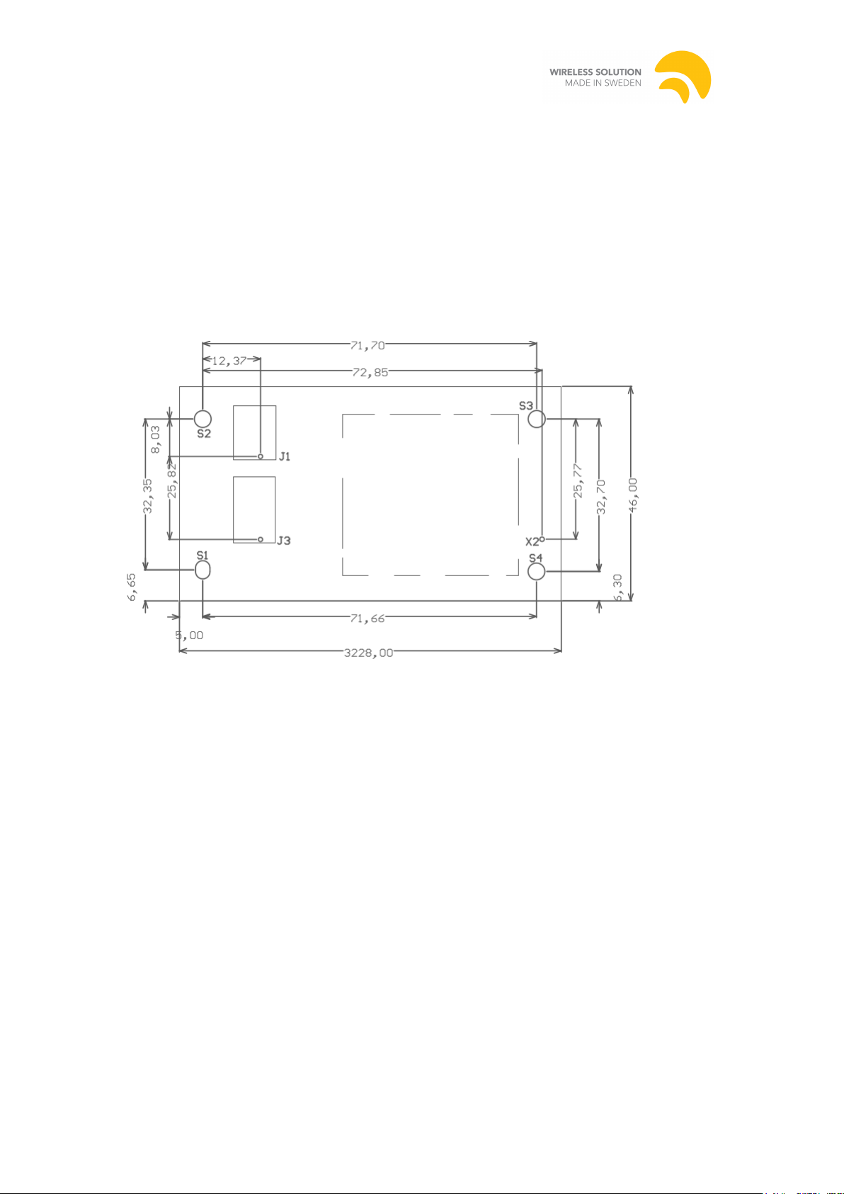
Auto Cad DXF files with file with relevant dimensions are available on request from
Wireless Solution. The total height of Pro cards is 11 mm, the highest point it the pin
header, take into consideration the receptacle that you choose.
2.1 Pro L6 model
S2, S3 and S4 is M3 holes
S1 is a slot 3.9 x 3.1 mm
X2 is the antenna connector
3 Antennas
Note that several aspects, including physical placement, should to be considered with
external antennas.
W-DMX installations use W-DMX supplied RP-SMA cable and ship with the
standard dual band indoor 4dBi antenna.
Page 9

Revision 4
Author: Anders Zellén
Wireless Solution Sweden Sales AB
Stureparksvägen 7 – 451 55 Uddevalla – Sweden
+46 522 511 511 Tel. +46 522 440 885 Fax.
Wirelessdmx.com [email protected]
4 Power Supply Considerations for Receivers and
Transceivers
Transceivers and receivers have very different power requirements. Please read the following
information carefully together with the electrical specifications at the end of this document.
4.1 Receivers
For a receiver only implementation a simple linear voltage regulator such as the common
7805 series is sufficient. Be sure to choose a package with sufficient cooling capabilities. A
TO-220 or D-Pak is usually a good choice.
4.2 Transceivers
As transceivers can draw high currents when transmitting, a more sophisticated solution is
generally required. It is especially important to make sure the supply can handle the brief
peaks.
The W-DMX cards have built in under voltage detection which protects the system from
permanent electrical damage, but data loss might still occur.
If the transceiver card is used as an RDM receiver, then you also need to take into
consideration the current used during transmission.
4.3 Power Indicator
The W-DMX card is equipped with an on-board green Power Indicator LED, which is lit
when the card is powered properly.
5 Interface Connectors, J1 and J3
The connectors J1 and J3 provide pins for power, DMX data, control signals and user
interface.
Pin 1, 2, and 3 of J1 will function as a DMX/RDM input on a Transmitter card and as a
DMX/RDM output on a Receiver card.
No provisions are made on the W-DMX TRX card for the secondary DMX data connections,
or any other form of data, that is sometimes carried by Pin 4 & 5 on 5 pin DMX XLR
connectors, and as such these two extra pins should never be connected to any pin on the
radio card.
5.1 Connector Types
J1 and J3 are both commonly available standard dual row 2.54mm (0.1”) pitch pin headers
J1 and J3 are located in such way so that they together fit in a 24 pin header.
9(23) 14/11/2014
Page 10

Revision 4
Author: Anders Zellén
Wireless Solution Sweden Sales AB
Stureparksvägen 7 – 451 55 Uddevalla – Sweden
+46 522 511 511 Tel. +46 522 440 885 Fax.
Wirelessdmx.com [email protected]
J1
Tx/Rx Sel In
10 9 LED Mode (L6)
Pwr, non reg.
8 7 Gnd
+5V 6 5
LED Status
Button
4 3 RS485+/TTL Tx
RS485-/TTL Rx
2 1 Gnd
J3 (only available on L6)
RS485/TTL Sel.
12
11
RS485 Ext. Dir
MOSI
10 9 MISO
SCK 8 7
Slave CS
Overlay CS
6 5 Slave IRQ
Inter B
4 3 Inter A
Tx/Rx Out
2 1 Reset
Pin
Name
Dir
Description
Notes
J1
10
Tx/Rx Sel In
I/O
Select/Indicate Transceiver Direction
(On L5, only used for input)
330ohm series resistor
J1 9 LED Mode
O
Indicates G3/G4L/G4H mode
(On L5, internal usage)
Active High
J1 8 Pwr, Non. Reg.
P
Unregulated power in, only on select models
J1 7 Gnd
P
Ground
J1 6 +5V P Regulated 5V
J1 5 LED Status
O
Status Led
Active High
J1 4 Button
I
Function Button, Internal Pullup
Active Low
J1 3 RS485+/TTL Tx
I/O
RS485 Positive or TTL level Tx
J1 2 RS485-/TTL Rx
I/O
RS485 Negative or TTL level Rx
J1 1 Gnd
P
Ground
J3
12
RS485/TTL Sel.
I
Select RS485/TTL level. Internally pulled low to select RS485
J3
11
RS485 Ext. Dir.
O
RS485 direction for external driver
J3
10
MOSI
O
SPI Data Out
J3 9 MISO
I
SPI Data In
J3 8 SCK O SPI Clock
J3 7 OSP CS#
O
Chip Select for slave MCU Interface
Active Low
J3 6 Overlay CS
O
Chip Select for Overlay Interface
Active High
J3 5 OSP IRQ#
I
Slave interrupt request
Active Low
J3 4 Inter B
I/O
Reserved, Do not connect
J3 3 Inter A
I/O
Reserved, Do not connect
J3 2 Tx/Rx Out
O
Signals transceiver mode
Active High
J3 1 Reset
I
MCU reset, internally pulled high
Active Low
5.2 Pin out for the W-DMX Pro card
10(23) 14/11/2014
Page 11

Revision 4
Author: Anders Zellén
Wireless Solution Sweden Sales AB
Stureparksvägen 7 – 451 55 Uddevalla – Sweden
+46 522 511 511 Tel. +46 522 440 885 Fax.
Wirelessdmx.com [email protected]
6 DMX Interface and Specification
The transceiver provides a non-isolated RS-485 signal interface that is used in the R-512 unit
in parallel with an TTL level interface used in the other units where the carrier board
implement an isolated RS-485 interface.
To select TTL levels instead of RS485, pull the RS485/TTL Sel. pin (J3:12/Slot In:16) high.
Refer to the connector description for pin numbering.
Note that all normal DMX/RDM timing requirements apply regardless of signal levels.
6.1 Conformity to ANSI E1.11-2008
The W-DMX G4S conforms to the USITT DMX-512A standard with the following
specifications:
6.1.1 §10.5.3 Loss of data handling procedure.
6.1.1.1 Loss of DMX or Radio Link
Recovery of DMX at the receiving end after loss and resumption of DMX signal at the
transmitter is within 5 ms.
Recovery after complete loss of the radio link is less than 50ms when there are normal
reception conditions.
A W-DMX TRX receiver card will turn its DMX/RDM output into high impedance state
upon loss of DMX at the transmitter, or loss of radio link at the receiver.
The W-DMX G4S radio protocol employs what is known as Data Safe which has redundancy
on the packets sent over the air and send each DMX slot at least twice, and distributes them
on different frequencies, thereby greatly improving reliability and data fidelity, and greatly
reducing the chance of data loss caused by spurious interference when compared to other
Wireless DMX products. However, no radio system is 100% noise proof and if higher data
reliability where no bytes can be allowed to be wrong, the user needs to implement some kind
of error correction scheme above the DMX layer.
6.1.1.2 Loss of Power
Configuration information is stored in non-volatile memory and will not be lost upon loss of
power to the card. This information includes system setup and settings for power level and
frequency hopping pattern, as well as connection information for the previous transmitter the
unit was connected to. The non-volatile memory will retain its information for a minimum of
10 years without power.
Upon loss of power to the card the RS-485 DMX ports of the device will go into a high
impedance state, as mandated by the DMX standard.
Resumption of wireless transmission and reception of data takes place within a second after
power is reapplied to the card, depending on configuration.
6.1.2 §10.5.4 Packet processing latency.
The W-DMX systems have an average latency of 3ms from when data comes in to the radio
transmitter to when data is transmitted from the radio receiver when running in G4S radio
mode.
11(23) 14/11/2014
Page 12

Revision 4
Author: Anders Zellén
Wireless Solution Sweden Sales AB
Stureparksvägen 7 – 451 55 Uddevalla – Sweden
+46 522 511 511 Tel. +46 522 440 885 Fax.
Wirelessdmx.com [email protected]
Time min
Time max
Transceiver
Idle / Normal Operation
-
-
Link Receivers
100ms
3s
6.1.3 §10.5.5. NULL START Code functionality.
The W-DMX system forwards all packets regardless of start code in G4S mode, with the
exception of RDM start codes, which are processed internally on RDM enabled devices. In
other radio modes only NULL START Code packages is forwarded.
6.1.4 §10.5.6 Slot footprint.
The W-DMX system has a slot footprint of zero.
7 User Interface
The W-DMX system offers the following user interface options:
1. A push button (called function switch) and one or more status LEDs.
2. Overlay Interface
3. RDM interface
IMPORTANT! The Function Switch and the LED Indicator are the minimum
requirement for a working implementation. Without a way to interact with the system
the user may be left with an inoperable device.
7.1 Function Switch
The function switch can be a simple momentary push button connected between pin J1:4 and
ground or a transistor controlled by a micro controller. Refer to the table below for exact
timings required.
7.1.1 Link
When the button is pressed for a brief period of time the transmitter will link unlinked
receivers within range.
7.1.2 Unlink
On a transmitter holding the button for more than 3s and then releasing it will cause any
linked receivers to unlink.
On a receiver holding the button for more than 3s will cause that receiver to unlink.
7.1.3 Transceiver direction
Cards read the state of pin J1:4 at start up and will, if the pin is low, switch mode. A receiver
becomes a transmitter and vice versa. When J1:4 is held low at boot, the boot loader will be
bypassed, giving control to the main program immediately. Thus the pin only has to be held
low for a very short period of time.
7.1.4 Function Switch Timing
The functionality provided by the Function Switch input and its timing parameters are
described in the table below.
12(23) 14/11/2014
Page 13

Revision 4
Author: Anders Zellén
Wireless Solution Sweden Sales AB
Stureparksvägen 7 – 451 55 Uddevalla – Sweden
+46 522 511 511 Tel. +46 522 440 885 Fax.
Wirelessdmx.com [email protected]
Unlink all Receivers
3s
10s
Toggle direction at boot (Flex Button Mode only)
100ms
-
Receiver
Idle / Normal Operation
- - Unlink from a Transmitter
3s
13(23) 14/11/2014
Page 14
Revision 4
Author: Anders Zellén
Wireless Solution Sweden Sales AB
Stureparksvägen 7 – 451 55 Uddevalla – Sweden
+46 522 511 511 Tel. +46 522 440 885 Fax.
Wirelessdmx.com [email protected]
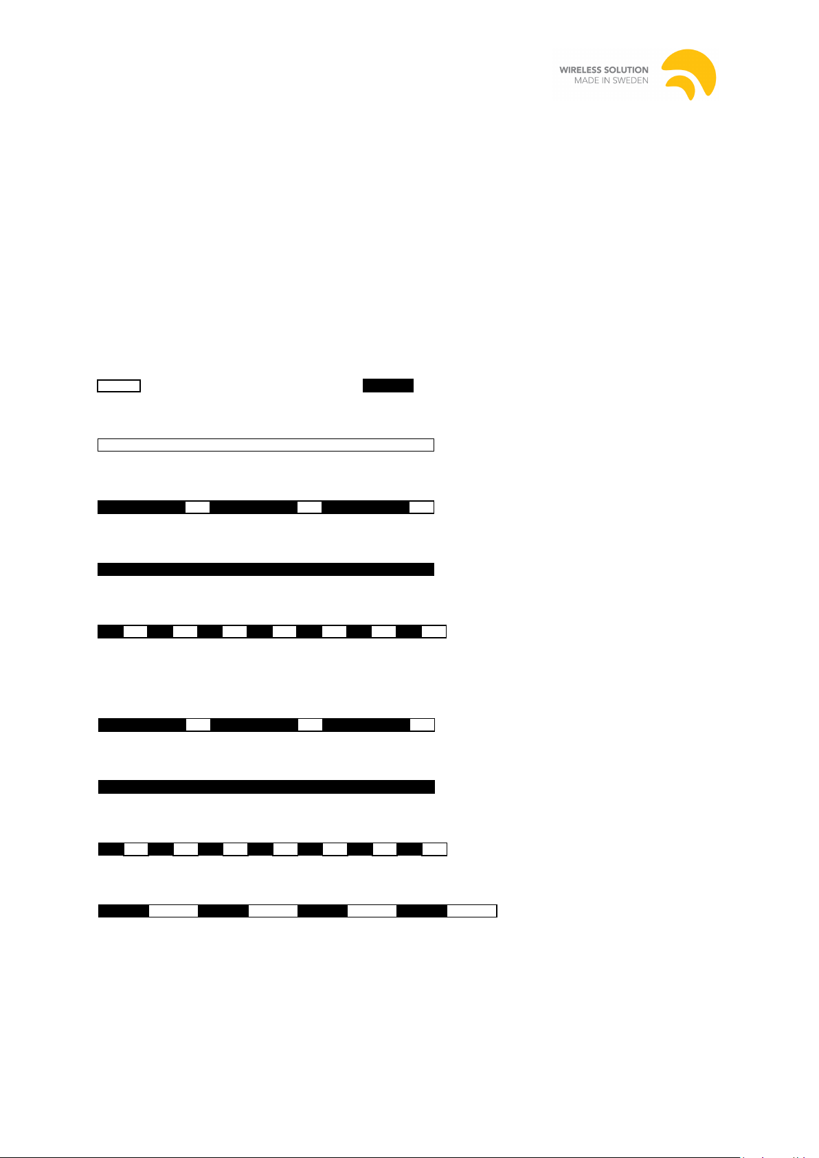
Continuously Off = not assigned to a transmitter
On 900ms / Off 100ms = assigned to a transmitter, but no DMX present
Continuously On = assigned to a transmitter and DMX present
On 100ms / Off 100ms = link to transmitter lost or linking to transmitter
On 900ms / Off 100ms = no DMX present
Continuously On = DMX present
On 100ms / Off 100ms = linking receivers
On 500ms / Off 500ms = unlinking all receivers
7.1.5 Status Indicator LED
The Status LED indicates the current status of the wireless connection and the presence of
DMX data. The status is valid after start-up process has finished after ~1.7s (worst case) from
power on
The LED is active high, and should be connected between J1:5 and ground, for example J1:7
via a series resistor.
The LED output can deliver a maximum of 15mA. For the average LED a series resistor of
330ohms will work well.
The indications below are valid during steady state, that is in normal running mode after the
boot loader has finished.
/ “Off” denotes a dark LED and / “On” denotes a lit LED.
7.1.5.1 LED Indication - Receiver:
7.1.5.2 LED Indication - Transmitter:
14(23) 14/11/2014
Page 15

Revision 4
Author: Anders Zellén
Wireless Solution Sweden Sales AB
Stureparksvägen 7 – 451 55 Uddevalla – Sweden
+46 522 511 511 Tel. +46 522 440 885 Fax.
Wirelessdmx.com [email protected]
7.1.6 Mode Indicator LED, L6 only
The Mode LED indicates whether the W-DMX device is currently operating in G3, G4, G4S
2.4GHz or G4S 5.8GHz mode.
G4S 5.8 GHz mode: on 500ms / Off 500ms
The LED is active high, and should be connected between pin J1:9 and ground, for example at
pin J1:7, via a series resistor.
The LED output can deliver a maximum of 15mA. For the average LED a series resistor of
330ohms will work well.
15(23) 14/11/2014
Page 16
Revision 4
Author: Anders Zellén
Wireless Solution Sweden Sales AB
Stureparksvägen 7 – 451 55 Uddevalla – Sweden
+46 522 511 511 Tel. +46 522 440 885 Fax.
Wirelessdmx.com [email protected]
Name
Bit
Text
Color
Description
Signal 5
0 Green
Signal strength
Signal 4
1 Green
Signal strength
Signal 3
2 Green
Signal strength
Signal 2
3 Yellow
Signal strength
Signal 1
4 Red
Signal strength, G4/G4S indication on
transmitter
Transmit Mode
5
TX
Green
Radio transmitter
Control Mode
6
CTRL
Red
In control mode
Link
7
LINK
Green
Link established
Data
8
DATA
Green
DMX Data present
Power
9
PWR
Blue
Power on indication
Reserved
1011
Receiver Mode
12
RX
Green
Radio receiver
G4 Mode
13
G4
Green
Mode indication
RDM
14
RDM
Green
RDM on/off
Reserved
15
Parameter
Min
Typ.
Max
Unit
Comment
SPI Mode
0. Clock idles low. Data valid on
leading clock edge
Data Bit Rate
2.5 MHz
Bit order
Most Significant Bit first
7.2 LED Overlay Interface, L6 only
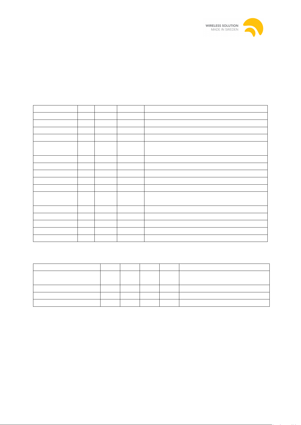
This interface is implemented on the W-DMX BlackBox/WhiteBox range.
The overlay interface consists of an SPI interface that shifts out data for the LEDs as
described below. To avoid flicker a latched shift register is recommended.
The SPI speed is 2.5MHz and Overlay CS is pulled high before the output start and pulled
low after the SPI output has ended.
.
7.2.1 LED order
7.2.2 SPI Settings
16(23) 14/11/2014
Page 17

Revision 4
Author: Anders Zellén
Wireless Solution Sweden Sales AB
Stureparksvägen 7 – 451 55 Uddevalla – Sweden
+46 522 511 511 Tel. +46 522 440 885 Fax.
Wirelessdmx.com [email protected]
7.3 W-DMX RDM Interface
The W-DMX transceivers can act as a managed RDM proxy. Please see the separate
document “W-DMX RDM Manual” for details.
8 In System Software updates (Boot Loader Support)
The W-DMX device is equipped with a so called boot loader which allows the end user to
upgrade the device to a new software version even when installed in a fixture.
When power is applied to the W-DMX device the boot loader is entered and the Status LED
is lit as an indication. In this mode it waits for a sync signal from a W-DMX USB Dongle. If
no signal is received within 0.5s normal operation is resumed and the system enters the main
program.
If no valid program is found on the W-DMX card, for example because of an interrupted
upgrade, the Status LED will blink slowly to indicate this.
During software upgrade the Status LED blinks once for every valid packet received.
When software update is performed, configuration settings on the device is not affected and
therefore the software lock that disable 2.4 functionality is not affected.
8.1 Design considerations
Designing for boot loader compatibility requires a few considerations that might not normally
be included in a simple receiver setup:
8.1.1 Bidirectional connection
In a simple fixture external DMX ports might not be present. For the boot loader to be able to
communicate with the USB Dongle a bi-directional connection is required between the DMX
terminals of the W-DMX device and an external connector.
Some fixtures offer an external XLR connector for DMX input, often to a separate UART on
the uC. This will not work as the boot loader requires unhindered control of the data lines.
Also, most repeaters/splitters will not work as the boot loader protocol uses the non-DMX
data rate of 57.6kbps.
8.1.2 A means of resetting the device
Since the W-DMX device enters the boot loader at start up, some way to restart the device is
required in order for upgrades to work. This can be done either by power cycling the W-DMX
card or by pulling the RESET pin low on an L6 card.
If the fixture controls the power state of the W-DMX device care must be taken to ensure that
the data lines are available to the device at start up.
17(23) 14/11/2014
Page 18
Revision 4
Author: Anders Zellén
Wireless Solution Sweden Sales AB
Stureparksvägen 7 – 451 55 Uddevalla – Sweden
+46 522 511 511 Tel. +46 522 440 885 Fax.
Wirelessdmx.com [email protected]
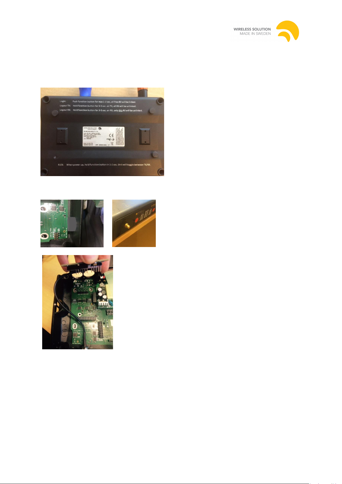
9 Installation Guidelines
The PCB is installed on the carrier board.
The box is opened by unscrew 4 screws from the bottom of the unit, the screws is hidden by
rubber feet’s.
The electrical installation includes two parts:
Push out the plug for the antenna connector and then fasten the antenna cable in the chassis
Connect the MCX connector on the antenna cable on the radiocard
18(23) 14/11/2014
Page 19
Revision 4
Author: Anders Zellén
Wireless Solution Sweden Sales AB
Stureparksvägen 7 – 451 55 Uddevalla – Sweden
+46 522 511 511 Tel. +46 522 440 885 Fax.
Wirelessdmx.com [email protected]
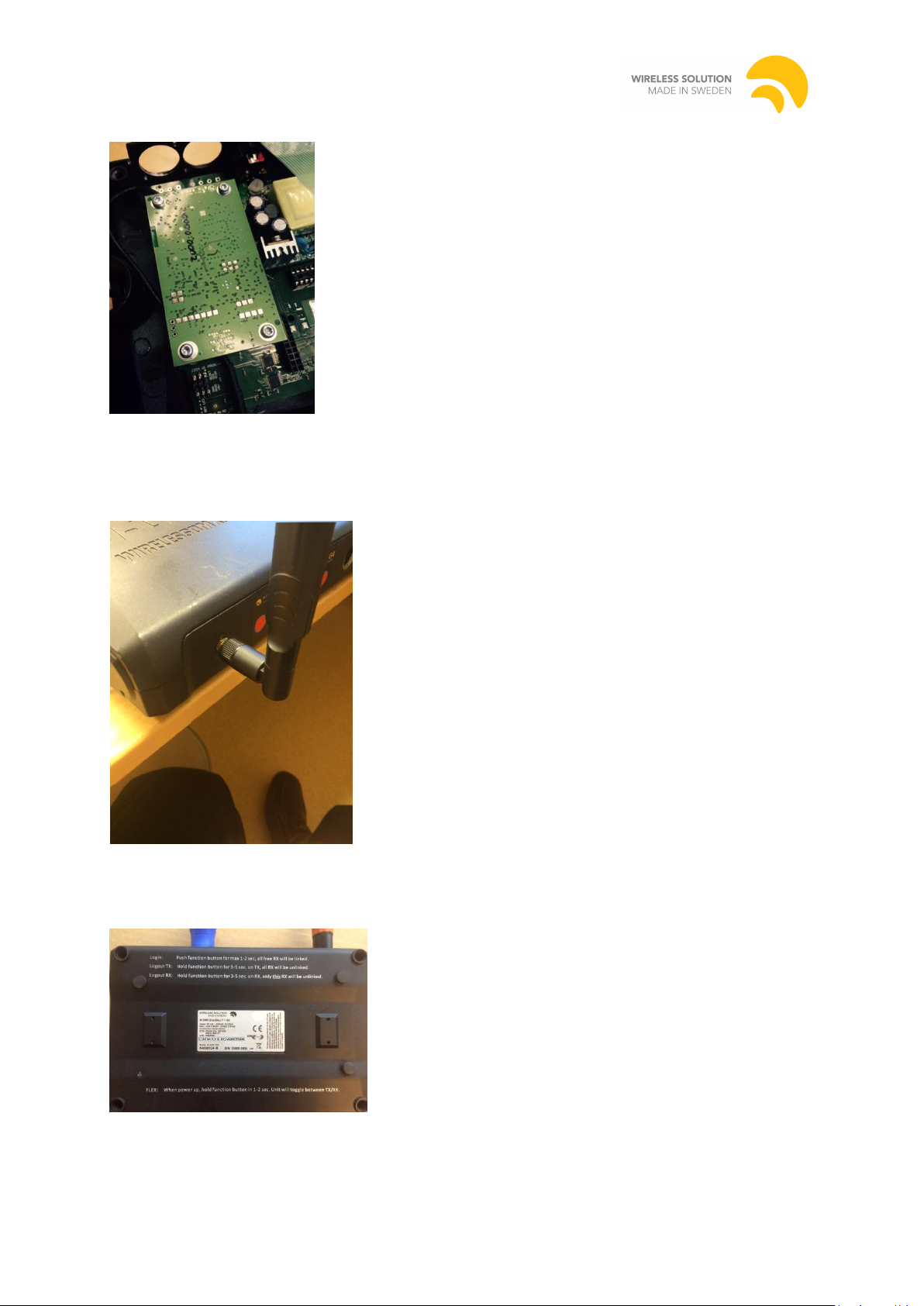
Connect the pin header on the radiocard to the carrier board and fixate with four screws.
To close the unit, close the LID and fasten the 4 screws in the bottom, put back the rubber
feet.
Connect the antenna to the SMA connector on the box
Finally when the installation is completed, take the label
“Contains FCC ID: NY2-WDMXTRXDB” and fasten it on the product label on the bottom of
the unit.
19(23) 14/11/2014
Page 20
Revision 4
Author: Anders Zellén
Wireless Solution Sweden Sales AB
Stureparksvägen 7 – 451 55 Uddevalla – Sweden
+46 522 511 511 Tel. +46 522 440 885 Fax.
Wirelessdmx.com [email protected]
Parameter
Min.
Typ.
Max.
Unit
DC Supply
5V DC input
4.9
5.0
5.1 V LED Pin output source current
20
mA
DMX interface
Maximum number of units on the DMX/RS485 bus
As per the DMX Standard
DMX data rate1
250
kbps
ESD protection, human body model
None
kV
RF characteristics (5.8GHz)
Maximum Output Power
Actual limit depends on local regulations
- -
27.0
500
dBm
mW
Frequency Range of operation
5744
5821
MHz
Channel bandwidth
1
MHz
Sensitivity at 0.1% BER
-96 dBm
Range with standard 4dBi antenna (measured)
400
m
1
The radio card is detected by signal level on pin J1.5 that is driven to GND or 5V depending
on card status, normal this pin is floating to ~2.5V. Therefore no further installation is needed.
By this detection, the host product is initialized for use of the radiocard.
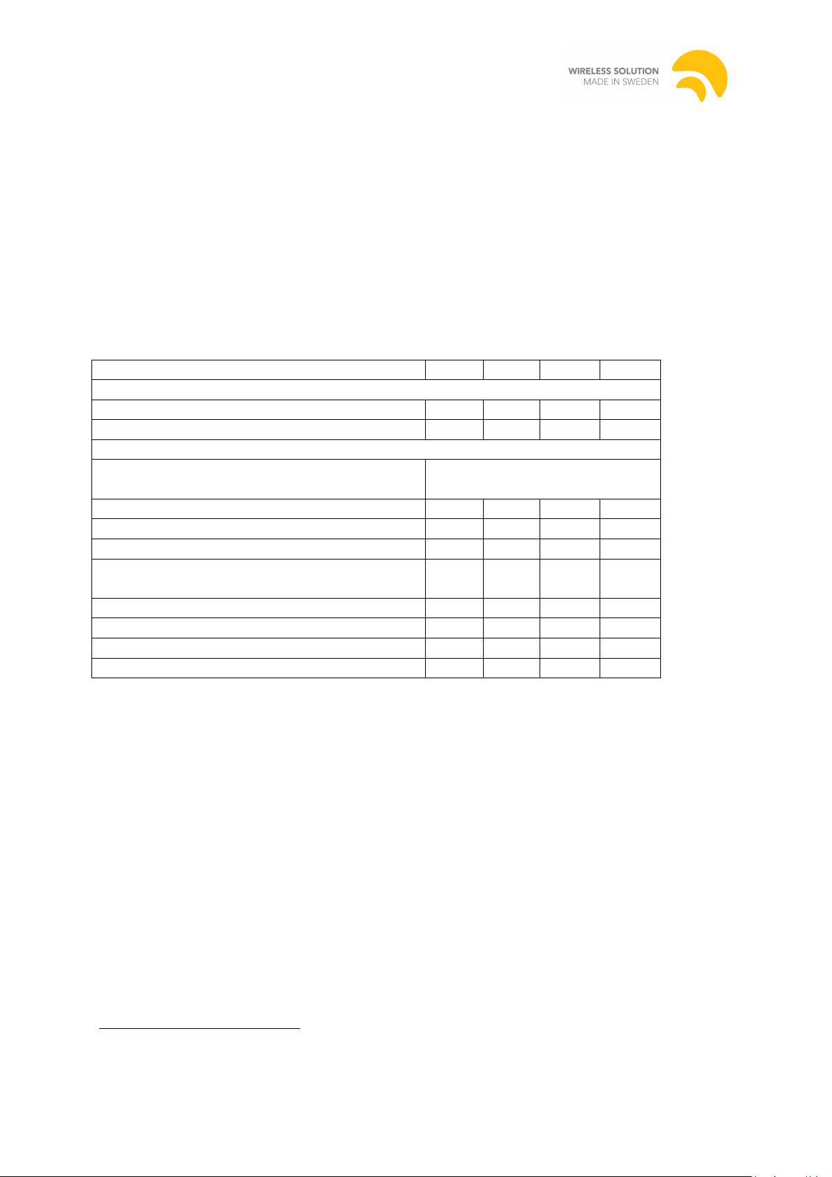
10 Specifications
Exceeding the values specified in the tables below will cause permanent damage and void any
warranty.
10.1 Electrical Specifications
Slew rate limited for minimum of EMI in un-terminated networks.
20(23) 14/11/2014
Page 21
Revision 4
Author: Anders Zellén
Wireless Solution Sweden Sales AB
Stureparksvägen 7 – 451 55 Uddevalla – Sweden
+46 522 511 511 Tel. +46 522 440 885 Fax.
Wirelessdmx.com [email protected]
Parameter
Min.
Typ.
Max.
Unit
Ambient Operating Temperature
-20 453
C
Relative Humidity4
20 80 % Option: coated Relative Humidity4
20 95
%
1
2
3
4
Code1
Typ.2
(mA)
Max2
(mA)
Antenna
Operating
Mode
Typ. input
power (W)
Max input
power (W)
WDMX-TRX
470
850
MCX
Tx
WDMX-TRX
80
95
MCX
Rx
DC current consumption
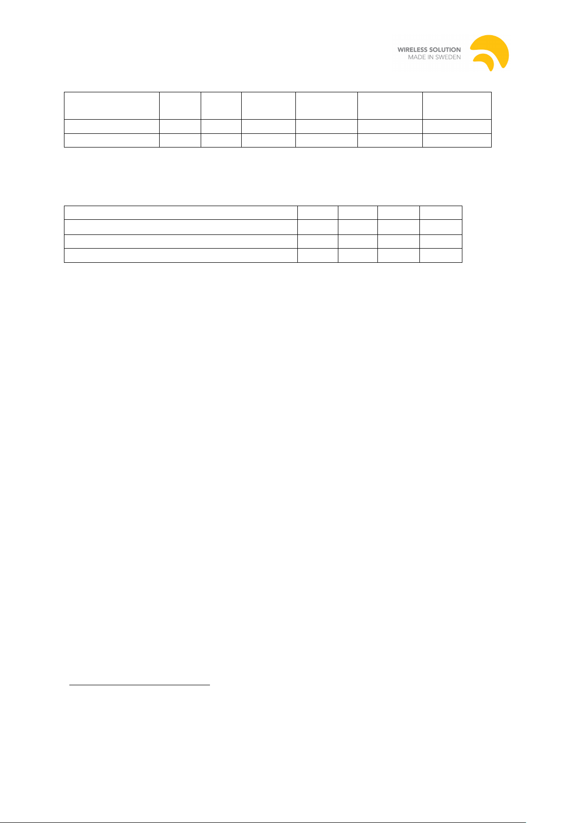
Environmental requirements
Refer to Appendix 1 for Order Codes and a detailed description.
Measured with no DMX on input/output and no LEDs.
Consult with Wireless Solution for temperatures exceeding 45C.
Non-condensing.
21(23) 14/11/2014
Page 22

Revision 4
Author: Anders Zellén
Wireless Solution Sweden Sales AB
Stureparksvägen 7 – 451 55 Uddevalla – Sweden
+46 522 511 511 Tel. +46 522 440 885 Fax.
Wirelessdmx.com [email protected]
Order Code
Name
Input
Voltage
Band
(GHz)
Direction
Selector
Ant.
RDM
Notes
WDMX-TRX
PRO G4, Transceiver,
MCX Connector.
DMX/RDM. 5,8GHz
US Market only
5V
5.8
J1:4
MCX
Yes
Transceiver,
5.8GHz only
Appendix 1. Ordering Codes for Radio Cards
22(23) 14/11/2014
Page 23

Revision 4
Author: Anders Zellén
Wireless Solution Sweden Sales AB
Stureparksvägen 7 – 451 55 Uddevalla – Sweden
+46 522 511 511 Tel. +46 522 440 885 Fax.
Wirelessdmx.com [email protected]
11 Notes
23(23) 14/11/2014
 Loading...