

Page 1

4-Zone Mouse Senso
r
Integration Guide
Interlink Electronics
®
FSR
4-Zone Mouse Sensor and USB Interface Chip
Force Sensing Resistors®
Integration Guide
Document P/N: EIG-10003 Rev. A
Interlink Electronics and the six dot logo are registered trademarks of Interlink Electronics, Inc.
www.interlinkelectronics.com
Page 2

4-Zone Mouse Senso
r
Integration Guide
Table of Contents
1.0
Introduction.................................................................................................................... 1
2.0 Scope ................................................................................................................................ 1
3.0 Theory of Operation .................................................................................................... 2
4.0 Mounting .......................................................................................................................... 4
5.0 Connection ..................................................................................................................... 6
6.0 Actuator ........................................................................................................................... 9
7.0 USB Information ......................................................................................................... 10
7.1 Device PID and VID ............................................................................................. 10
7.2 Data Packet ......................................................................................................... 10
7.3 USB Suspend Mode ............................................................................................ 10
8.0 Electrical Specifications ......................................................................................... 11
8.1 Controller Chip ..................................................................................................... 11
8.2 Clock Signal ......................................................................................................... 11
8.3 Operating Current ................................................................................................ 11
8.4 Mouse Speed Configuration ................................................................................ 11
9.0 Controller Chip Example Bill of Materials ......................................................... 13
10.0 Orderable Part Numbers .......................................................................................... 14
11.0 Intellectual Property & Other Legal Matters .................................................... 14
12.0 Contact Interlink Electronics ................................................................................ 15
www.interlinkelectronics.com
Page 3

4-Zone Mouse Senso
r
Integration Guide
1.0 Introduction
The 4-zone Force Sensing Resistor (FSR) paired with a suitable actuator can be implemented as
a finger-actuated "mouse" pointing module. This pointing module provides accurate 360-degree
mouse control. Users control direction by applying pressure in the direction of the desired
movement and adjust speed by altering the amount of pressure on the device.
The purpose of this document is to guide users through the successful integration of a USB
controller chip (microprocessor) and the Interlink Electronics 4-zone FSR.
2.0 Scope
This Integration Guide provides the OEM integrator with all of the necessary technical information
to successfully integrate the Interlink Electronics 4-zone FSR and USB microcontroller chip into
products such as:
NEMA-rated industrial pointing devices
industrial keyboards
military computers
Sensor and chip part numbers are detailed in section 10.
www.interlinkelectronics.com
1
Page 4

4-Zone Mouse Senso
r
Integration Guide
3.0 Theory of Operation
The most basic FSR consists of two membranes separated by a thin air gap. The air gap is
maintained by a spacer around the edges and by the rigidity of the two membranes. One of the
membranes has two sets fingers which are interdigitated and electrically distinct; each set
connects to one trace on the tail. The other membrane is coated with FSR ink. When the two
layers are pressed together, the FSR ink shorts the two traces together with a resistance that
depends on applied force.
Figure 1: Exploded view of a standa rd single-zone FSR
www.interlinkelectronics.com
2
Page 5

4-Zone Mouse Senso
r
Integration Guide
The 4-zone FSR is simply a combination of four basic FSRs arranged in a North, South, East,
West pattern. Each zone interpenetrates into the two zones on either side of it. This overlapping
of the zones allows us to determine how much force is in each zone relative to the others. Once
the relative force in each zone is known, the direction and speed of the mouse pointer can be
determined.
Figure 2: Exploded view of 4-zone FSR
www.interlinkelectronics.com
3
Page 6

4-Zone Mouse Senso
r
Integration Guide
4.0 Mounting
Mechanical installation of the 4-zone FSR has a few critical features that must be considered for
mounting.
To ensure proper registration of the sensor, crop marks made in the copper layer should be
included in the PCB layout. Sufficient registration accuracy is achievable by placing the FSR by
eye using the crop marks.
Figure 3: PCB copper layer showing crop mark locations and size/location of pads.
(All dimensions in millimeters)
www.interlinkelectronics.com
4
Page 7

4-Zone Mouse Senso
r
Integration Guide
Copper traces should not be routed underneath the sensor; they will interfere with its proper
operation. If traces must be routed towards the sensor, vias should be used to bring the traces to
another layer of the board before the sensor’s active area is reached. Interlink recommen ds that
the vias do not extend more than 1.27mm from the bottom of the pads. (See Figure 3)
Figure 4: 4-zone FSR showing overall dimensions, center of part, and size/location of contacts.
(All dimensions in millimeters)
www.interlinkelectronics.com
5
Page 8

4-Zone Mouse Senso
r
Integration Guide
Heat generated during the soldering of components can damage the FSR. Therefore, the sensor
should not be mounted until PCB assembly is complete. When laminating the FSR to the PCB, be
sure to use a hard roller or other depression tool to ensure proper bonding of the sensor’s
pressure-sensitive adhesive and the removal of any air bubbles.
Figure 5: 4-zone FSR pinout reference. Sensor is shown with silver contacts facing away.
5.0 Connection
The 4-zone FSR is connected to the PCB with either a pressure-sensitive z-axis conductive
adhesive or a heat-bonded z-axis conductive adhesive. Both methods of adhesion are meant to
provide an electrical, not mechanical bond; therefore, a mechanical means of applying constant
pressure to the joint should be incorporated into the mounting of the 4-zone FSR. This will
prevent the delamination of the adhesive, which can lead to an open circuit and failure of the
module.
Recommended Conductive Adhesives:
3M 9703/9705 Anisotropic Electrically Conductive Adhesive Transfer Tape
3M 7303 Heat-Bondable Anisotropic Electrically Conductive Adhesive Film
www.interlinkelectronics.com
6
Page 9

4-Zone Mouse Senso
r
Integration Guide
Constant pressure on the sensor contacts can be applied in a couple different ways. One method
is to use the module’s case or housing to apply pressure to the joint through a piece of rubber.
The rubber is used to take up tolerances in the design and can be made as an extension of the
actuator (See Figure 4). This design can provide a long-lasting high-quality conn ection and is
appropriate for most designs.
Figure 6: Cross section view showing constant pressure being applied to the sensor contacts by the
module's case through an extension of the rubber actuator
www.interlinkelectronics.com
7
Page 10

4-Zone Mouse Senso
r
Integration Guide
Another connection method is to use a screw-down metal clamp to apply pressure to the sensor
contacts through a piece of rubber. Again, the rubber is used to take up tolerances in the design.
This is the most robust connection method and is appropriate for military applic ations.
Figure 7: Exploded view of screw-down metal clamp assembly
www.interlinkelectronics.com
8
Page 11

4-Zone Mouse Senso
r
Integration Guide
6.0 Actuator
An actuator must be used to achieve the best pointing results with the 4-zone FSR. There are
certain features on the actuator that are of special importance and extra care should be taken
when designing them.
Proper alignment of the actuator over the sensor is essential for implementing a successful
pointing device. Section 4 shows that the 4-zone FSR is registered to crop marks on the PCB;
therefore, a registration system designed to align the actuator to the PCB should adequately
ensure the correct alignment of the actuator to the 4-zone FSR.
To avoid preloading of the sensor, there must be a skirt surrounding the actuator. The skirt’s job
is to keep the actuator a minimum distance away from the sensor surface when not in use.
However, the skirt cannot be made too tall or the module’s actuation force will be adversely
affected. Other design elements that should be paid close attention to are the actuator diameter
and spherical radius.
Figure 8: Cross section view of actuator. (All dimensions in millimeters)
The actuator design is vital to the correct operation of the 4-zone FSR. Interlink Electronics
encourages customers to visit our website to download detailed CAD models of the rubber
actuator. www.interlinkelectronics.com/support
www.interlinkelectronics.com
9
Page 12

r
7.0 USB Information
Communication to the microprocessor is done via USB and:
Uses the low speed USB standard
Is compatible with any USB 1.1 or 2.0 host
Enumerates as HID device
The microprocessor reports data to the host at a rate of 50 reports/sec.
7.1 Device PID and VID
This IC’s Product ID (PID): 0x0002
Interlink’s Vendor ID (VID): 0x214A
7.2 Data Packet
The data packet from the chip is organized as:
Byte 0
o Bit 0 is the Left Button status
o Bit 1 is the Right Button status
o Bit 2 is the Middle button status
Byte 1 reports the X direction. The values range from -127 to +127 counts.
Byte 2 reports the Y direction. The values range from -127 to +127 counts.
4-Zone Mouse Senso
Integration Guide
7.3 USB Suspend Mode
The chip will not respond to a “suspend” command from the host. It will always stay active
with the current consumption as described in section 8.3.
Note: This device will not wake the host from suspend mode.
www.interlinkelectronics.com
10
Page 13

4-Zone Mouse Senso
r
Integration Guide
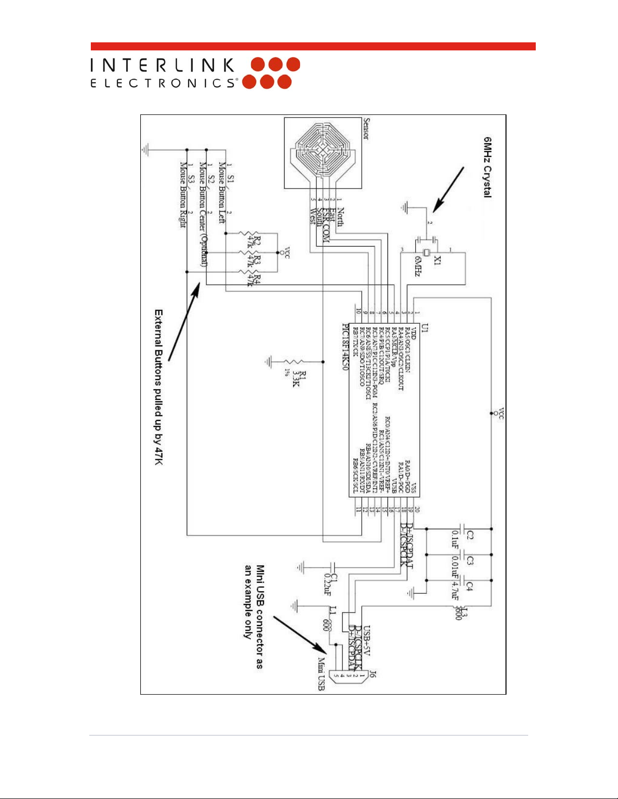
8.0 Electrical Specifications
8.1 Controller Chip
The controller chip used in this schematic is microchip PIC18F14K50. This IC, when
combined with Interlink’s proprietary FW, forms the controller engine for this sensor type.
8.2 Clock Signal
The default setting for a clock signal comes from a 6MHz crystal. To meet your needs,
Interlink can supply another version of this chip that will work with a direct clock signal.
8.3 Operating Current
Under normal operation, the device draws between 10mA to 12mA. This current draw is
typical of a full assembly (chip, sensor, etc).
8.4 Mouse Speed Configuration
Mouse speed can be configured by the user. R1 is the controlling factor for this. The
default value that is recommended by Interlink is 3.3K. If desired, the user can change
R1 values to slow down or speed up the mouse. In order to achieve a higher speed, the R1
value must be increased. Interlink recommends that the user should not exceed the limits
of 1K to 10K. (See Figure 8)
www.interlinkelectronics.com
11
Page 14
r
4-Zone Mouse Senso
Integration Guide
Figure 9: Recommended schematics for the controller chip
www.interlinkelectronics.com
12
Page 15

4-Zone Mouse Senso
r
Integration Guide
9.0 Controller Chip Example Bill of Materials
Used Part Type Designator Description
1 0.01uF C3 CAP,CER,0.01UF,10%,50V,0603
1 0.1uF C2 CAP,CER,0.1UF,10%,25V,0603
1 0.22uF C1 CAP,CER,0.22UF,5%,16V,0603
1 4.7uF C4 CAP,CER,4.7UF,10%,6.3V,0603
2 600 L1 L3
1 3.3K R1
3 47k R2 R3 R4
1 PIC18F14K50 U1
1 6MHz X1
3 No Momentary S1, S2, S3
Ferrite Chip, 600 Ohm, 500mA,
0805,SMD
Resistor, 3.3K OHM, Metal Film, 0402,
1%, 100ppm
Resistor, 47K OHM, Metal Film, 0402,
1%, 100ppm
MCU, PIC18F14K50, SSOP20
With Interlinks FW
Ceramic Resonator, 6MHz, SMD,
w/caps
Tactile & Jog Switches SPST-NO
200g Force GW SMD
Table 1: Controller chip example bill of materials
www.interlinkelectronics.com
13
Page 16

r
10.0 Orderable Part Numbers
Hardware Development Kit (54-00016)
o QTY 1 MicroModule Demo with USB Cable
1
o QTY 5 Programmed Microchip PIC18F14K50 microprocessors
o QTY 5 4-Zone Mouse Sensor, Square
o QTY 5 4-Zone Mouse Sensor, Square with Conductive Adhesive
o QTY 5 4-Zone Mouse Sensor, Square with tail and solder tabs
o QTY 1 USB Flash Drive with Product Literature
4 Zone Mouse Sensor and USB Interface Chip Datasheet
4 Zone Mouse Sensor and USB Interface Chip Integration Guide
Programmed Microprocessor, PIC18F14K50, Tape & Reel (54-00005)
4-Zone Mouse Sensor, Square (34-00002)
2
4-Zone Mouse Senso
Integration Guide
4-Zone Mouse Sensor, Square with Conductive Adhesive (30-79069)
4-Zone USB High Temperature Microprocessor (24-00178)
11.0 Intellectual Property & Other Legal Matters
Interlink Electronics holds several domestic and international patents for its Force Sensing Resistor
technology. FSR and Force Sensing Resistor are company trademarks. All other trademarks are
the property of their respective owners.
The product information contained in this document provides general information and guidelines
only and must not be used as an implied contract with Interlink Electronics. Acknowledging our
policy of continual product development, we reserve the right to change, without notice, any detail
in this publication. Since Interlink Electronics has no control over the conditions and method of use
of our products, we suggest that any potential user confirm their suitability for their own application.
1
Microprocessors covered here are capable of measuring any of the 4 Zone FSR’s offered by
Interlink Electronics.
2
Sensors provided with tail extension and solder tabs for ease of connection during hardware
development.
www.interlinkelectronics.com
14
Page 17

r
12.0 Contact Interlink Electronics
United States
Corporate Office
Interlink Electronics, Inc.
546 Flynn Road
Camarillo, CA 93012, USA
Phone: +1-805-484-8855
Fax: +1-805-484-9457
Web: www.interlinkelectronics.com
Sales and support: sales@interlinkelectronics.com
Japan
Japan Sales Office
Kannai-Keihin Bldg. 10F/1004
2-4-2 Ougi-cyo, Naka-ku
Yokohama-shi, Kanagawa-ken 231-0027
Japan
Phone: +81-45-263-6500
Fax: +81-45-263-6501
Web: www.interlinkelec.co.jp
4-Zone Mouse Senso
Integration Guide
www.interlinkelectronics.com
15
 Loading...