

Page 1
1. Specification
1) Input Voltage : 220V - 250V AC or 110V - 130V AC
2) Max. Recommended Capacity :10KW at 220 - 240V AC (45A) or 5.4KW at 110 - 130V AC (45A)
3) Connection with Heater : 2 pcs. of 235V 1500W Heater per Line x 3 Lines = 9000W
4) Temperature Range : -9℃ ~ 99℃ (Unit : 1℃)
5) Temperature Sensor : NTC10K (Cable Length 10m)
6) Working Condition : Temperature 1℃ ~ 65℃, Humidity 85% and below
7) Size : 220mm(W) x 185mm(H) x 60mm(D)
8) with a Remote Controller (RC-ITC10), Spare Fuse and Anchor Bolts inside.
★ The main power should be off when Thermostat Controller and Carbon Fiber Heaters are being installed.
★ Installation must be done by an electrician.
★ The earth wire must be connected.
★ Max. recommended capacity (15A) per line must not be exceeded.
★ Solely designed for InterHeat Carbon Fiber Heaters. Do not connect with other products.
2. Temperature Setting
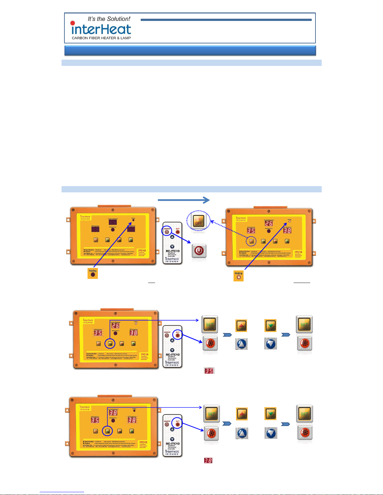
※ Power input ※ ※ Press ON/OFF button. ※
Connected heaters are not working. Connected heaters are working.
1) Setting of ON Temperature (Heaters will be on when Current Temperature is lower than ON Temp.)
2) Setting of OFF Temperature (Heaters will be off when Current Temperature reaches OFF Temp.)
or
1 pc. of 120V 1500W Heater per Line x 3 Lines = 4500W
(Refer to the Circuit Diagram on the page 2)
Temperature Setting
Temperature Setting
Heater off
( Blinking)
INTERHEAT INC. 9-7, Hwangsaeul-ro 200beon- gil, Bundang-gu, Seongnam, Gyeonggido, 13595 KOREA
TEL +82-70-7500-1201 / FAX +82-70-7500-1204 / [email protected]
INTERHEAT CHINA INC. 98 Xinghua Road, Xuezhuang Village, Jintan, Jiangsu 213200 CHINA
Instruction Manual of InterHeat Thermostat Controller ITC10
Heater on
Press
or
Press
on Remote
Press
Once
Press
Once
Press
Once
Press
Twice
( Blinking)
Page 2
3. Wire Connection
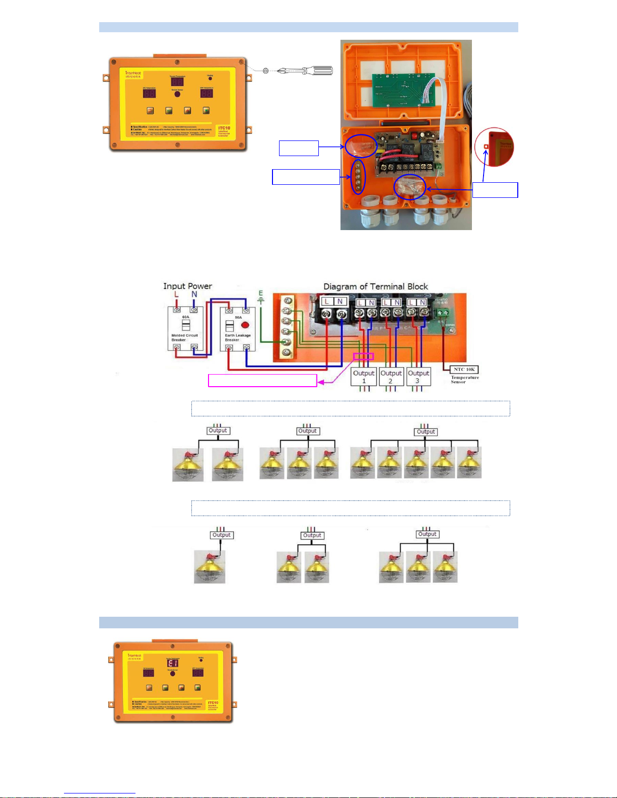
1) Open the cover with a screw driver
2) Circuit Diagram
4. Trouble Shooting
* Wire Connection of Thermostat Controller and Cabon Fiber Heaters
Spare Fuse
Anchor Bolts
Earth Terminal Block
Max. Recommended Capacity per line:
* Error code E1
E1 fault indicator light will turn on when sensor malfunction occurs or the cable
of sensor is poor connected. When this light is on, find the poor connected
point and fix it, or replace the sensor and cable both.
① 235V 1500W x 6 pcs. = 9000W (38A) Min. Wire Specification : Input (8mm²) / Output 1, 2, 3 (2.5mm²)
1500W or 1200W x 2 pcs. 900W x 3 pcs. 600W x 5 pcs.
② 120V 1500W x 3 pcs. = 4500W (38A) Min. Wire Specification : Input (8AWG) / Output 1, 2, 3 (13AWG)
1500W or 1200W x 1 pc. 900W x 2 pcs. 600W x 3 pcs.
 Loading...