

Page 1

ImageStation Z
Installation and Use
August 1997
DHA023320
Page 2

Warranties and Liabilities
The information and the software discussed in this document are subject to change without notice and should not be
considered commitments by Intergraph Corporation. Intergraph Corporation assumes no responsibility for any errors
in this document.
The software discussed in this document is furnished under a license and may be used or copied only in accordance
with the terms of the license. No responsibility is assumed by Intergraph for the use or reliability of software on
equipment that is not supplied by Intergraph or its affiliated companies.
All warranties given by Intergraph Corporation about equipment or software are set forth in your purchase contract,
and nothing stated in, or implied by, this document or its contents shall be considered or deemed a modification or
amendment of such warranties.
Copyright
1997, Intergraph Corporation including this documentation, and any software and its file formats and audio-visual
displays described herein; all rights reserved; may only be used pursuant to the applicable software license
agreement; contains confidential and proprietary information of Intergraph and/or other third parties which is
protected by copyright, trade secret and trademark law and may not be provided or otherwise made available without
prior written authorization.
Restricted Rights Legend
Use, duplication, or disclosure by the United States Government is subject to restrictions as set forth in subdivision
(c)(1)(ii) of the rights in technical data and computer software clause at DFARS 252.227-7013.
Unpublished rights reserved under the copyright laws of the United States.
Intergraph Corporation
Huntsville AL 35894-0001
Trademarks
Intergraph and the Intergraph logo are registered trademarks of Intergraph Corporation. ImageStation Z and TDZ
are trademarks of Intergraph Corporation.
Other brands and product names are trademarks of their respective owners.
Page 3

Contents
Introduction......................................................................................................................1
Getting Started .................................................................................................................2
Unpack the Equipment .......................................................................................................2
Gather the Tools.................................................................................................................2
Installing the Hardware................................................................................................... 3
Equipment Cautions ........................................................................................................... 3
Assemble the Cyborg Chair................................................................................................ 3
Assemble the Monitor Table .............................................................................................. 4
Assemble the Digitizer Table .............................................................................................4
Install the Base Unit and Keyboard.................................................................................... 4
Install the Monitor..............................................................................................................4
Install the Interface PEM....................................................................................................4
Install the Stereoscopic Subsystem..................................................................................... 7
Complete the Installation....................................................................................................8
Maintain the Equipment ..................................................................................................... 8
Activate the Stereoscopic Display...................................................................................... 9
Customize the Screen Tracking Area ............................................................................... 10
Troubleshooting the Installation ...................................................................................11
Troubleshoot the Altek Installation ..................................................................................11
Troubleshooting in Windows NT.......................................................................11
Troubleshooting in MS-DOS ............................................................................. 11
Troubleshoot the JPEG Installation.................................................................................. 13
Re-Installing the Software ............................................................................................. 14
Install the Altek Driver.....................................................................................................14
Install the StudioZ Producer Driver.................................................................................. 15
Understanding the JPEG System.................................................................................. 16
Adjusting System Ergonomics.......................................................................................17
Adjust the Cyborg Chair................................................................................................... 17
Adjust the Digitizer Table ................................................................................................ 18
Adjust the Monitor Table ................................................................................................. 18
Adjust the Monitor Position .............................................................................................18
Adjust the Keyboard Position...........................................................................................18
Adjust the Two-Handed Controller ..................................................................................19
Adjust the Stereoscopic Glasses....................................................................................... 19
Page 4

Page 5
Introduction
ImageStation Z is a softcopy production system that allows the user to view and process color imagery.
It features a D-sized digitizing surface and (using specially-designed glasses) stereoscopic viewing.
ImageStation Z is based on an Intergraph TDZ workstation, and includes furniture and other equipment
to comprise the complete system. It also includes separate documentation to guide you in setting up the
Intergraph TDZ workstation and assembling the KI workstation furniture.
This document describes how to install the hardware and software for an Intergraph ImageStation Z
system, and how to adjust and troubleshoot an ImageStation Z installation. It also contains a brief
description of image compression and decompression operations.
WARNING Only Intergraph field service personnel may perform the installation procedures in this
document.
CAUTION To successfully install the equipment, read all of the instructions carefully before proceeding with the
installation.
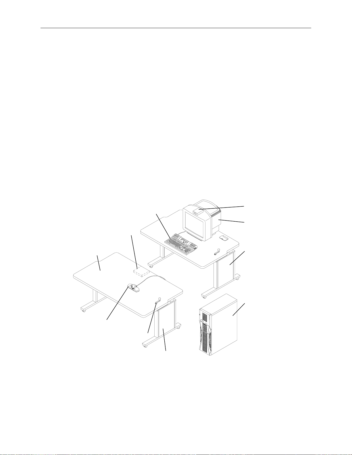
The following figure shows the components of an ImageStation Z system.
1
Infrared
Keyboard
PEM Bracket
D-sized
Digitizer
Table
Top
Two-Handed
Controller
NOTE Cyborg chair, Interface PEM, AC Adapter, handle grommet, and stereoscopic glasses are not shown.
Height
Adjustment
Handle and
Grommet
Digitizer
Stand
Transmitter
Monitor
Monitor Table
TDZ
Workstation
Base Unit
Page 6

2
Getting Started
Refer to the hardware documentation delivered with the Intergraph TDZ workstation for instructions on
setting up the basic system hardware and software. Use the instructions in this section to prepare to
install an ImageStation Z system.
Unpack the Equipment
Unpack all equipment from the shipping cartons. In addition to the Intergraph TDZ workstation base
unit, a keyboard, and a 21-inch, dual 21-inch, or 28-inch monitor, verify that you have the following
items:
u
Monitor table (FFUR0530)
u
Digitizer stand (FFUR0540), D-sized digitizer table top (CTIS1410) with a 15-pin to 9-pin Analog
to Digital Converter and three 9-pin RS-232 cables, PEM bracket (CFAB806F), Handle Grommet
(CGEN534A)
u
Wood screws (CPHW8760) for installing the PEM bracket
u
Interface PEM (MESAN360)
u
Two-handed controller (MESAL150)
u
Cyborg chair (FFUR0080)
u
A/C Adapter (CPWS1530 or CPWS1540)
Verify that you have the following components of the stereoscopic subsystem.
u
Stereoscopic glasses (CINF0110)
u
Infrared transmitter (CINF0120)
u
Stereo sync interface cable (MCBLV320)
If any of the listed items are missing or damaged, notify the Intergraph Customer Response Center at 1800-633-7248.
Gather the Tools
Gather the following tools to use when installing the system:
u
Phillips screwdriver, #2 (for PEM bracket assembly)
u
Phillips screwdriver, #3 (for furniture assembly)
u
Flat-bladed screwdriver, 1/4-inch, common (for cable installation)
u
Wrench, 1/2-inch, box-end or small adjustable (for table casters)
Page 7

Installing the Hardware
You will set up the components of the ImageStation Z hardware and software in the following order:
1. Cyborg chair
2. Monitor table
3. D-sized digitizer table
4. TDZ workstation base unit and keyboard
5. Monitor
6. Interface peripheral equipment module (PEM), two-handed controller, and cabling
7. Stereoscopic display subsystem
8. All power cords and setting switches
9. Altek and StudioZ Producer drivers
Detailed instructions for setting up these components are covered in the remainder of the document.
3
Equipment Cautions
Note the following cautions when installing and using ImageStation Z hardware:
u
The digitizer table work surface is a non-load bearing surface. Damage to sensitive parts may
occur if used for purposes other than intended.
WARNING Do not sit or lean on the digitizer table during or after assembly. Failure to heed this warning
may result in equipment damage.
u
The stereoscopic glasses are fragile. Handle them carefully. When not in use, store the glasses in
the box they came in or another suitable container.
u
Do not immerse the stereoscopic glasses in water or other liquids. Consult the documentation
delivered with the glasses for more information on the care and cleaning of the glasses.
Assemble the Cyborg Chair
To assemble the Cyborg chair:
1. Remove the installation/assembly instructions from the packing box and review them.
2. Remove the Chair Base/Casters assembly from the packing box and place it on the floor with the
casters down.
3. Remove the Chair Seat/Arms assembly from the packing box.
4. Insert the Chair Seat/Arms assembly post into the center hole of the Chair Base/Casters assembly.
Apply firm, even pressure to seat the post into the Base/Caster assembly.
Page 8

4
Assemble the Monitor Table
Remove the monitor table from the packing box. Refer to the documentation delivered with the KI
workstation furniture for detailed instructions for assembling the monitor table.
Assemble the Digitizer Table
To assemble the digitizer table:
1. Remove the digitizer table top assembly from the packing box. Remove all packing materials.
Place the table top assembly face down on a carpeted floor or on the packing materials.
2. Install the peripheral equipment module (PEM) bracket onto the underside of the digitizer table
top. Place the PEM bracket upside down with the open side of the PEM bracket facing away from
the table top. Install the four #5x 0.75-inch Phillips wood screws to mount the bracket to the table
top.
NOTE Position the angled side of the bracket toward the front of the digitizer table top.
3. Remove the digitizer stand from the packing box. Remove all packing materials and place the
digitizer stand on the digitizer table top.
4. Refer to the documentation delivered with the KI workstation furniture for instructions for securing
the digitizer stand to the digitizer table top.
5. Turn the assembled digitizer table upright.
6. Push the handle grommet into the opening for the height adjustment handle, and then install the
handle.
Install the Base Unit and Keyboard
Remove the TDZ workstation base unit and keyboard from their packing boxes. Refer to the TDZ
system’s hardware documentation for setup instructions.
Install the Monitor
WARNING The monitor is extremely heavy and could cause serious personal injury if dropped. Two
persons are required to lift and mount the monitor into place.
Remove the monitor from the packing box and place it on the monitor table.
Install the Interface PEM
The interface PEM is the electronics interface for the two-handed controller and the digitizer table.
To install the interface PEM:
1. Remove the interface PEM and its power cord from the packing box. Temporarily place the
interface PEM on top of the digitizer table in preparation for connecting the cables to the PEM.
Page 9

2. Connect the three RS-232 cables between the interface PEM, the Altek digitizer controller, and the
TDZ workstation base unit as described. Refer to the following figure.
Altek Digitizer Controller
Power Cursor RS-232
RS-232
Cable
Interface PEM
TDZ
Workstation
Base Unit
5
Tablet RS-232
HC Power
Two-Handed
Controller
with 25-pin
Cable
RS-232
Cable
COM 1
RS-232
Cable
COM 2
To connect the cables:
1. Connect one end of an RS-232 cable to the port labeled RS-232 on the interface PEM. Connect
the other end of the cable to COM 2 port on the TDZ workstation base unit. Tighten the cable
screws.
2. Connect the 25-pin cable from the two-handed controller to the port labeled Hand Controller on
the interface PEM. Tighten the cable screws.
3. Connect one end of an RS-232 cable to the port labeled Tablet on the interface PEM. Tighten the
cable screws. The other end of this cable is attached in Step 5.
Page 10

6
4. Slide the interface PEM into the PEM bracket mounted to the underside of the digitizer table.
Refer to the following figure.
PEM
Bracket
Interface PEM
NOTE Ensure that the cables extend to the back of the interface PEM. Verify that the front feet of the
interface PEM install into the holes provided in the PEM bracket. These holes provide a positive lockdown to prevent unwanted movement of the interface PEM.
5. The Altek digitizer controller is pre-mounted on the underside of the table as shown in the
following figure. Connect the 15-pin to 9-pin Analog to Digital converter to the port labeled
Cursor on the Altek digitizer. Connect the other end of the RS-232 cable that you connected to
Tablet in step 3, to the 15-pin to 9-pin Analog to Digital converter. Tighten the cable screws.
Altek
Digitizer
Controller
15-pin to 9-pin
Analog to Digital
Converter
Interface PEM
To COM 1
To Tablet
AC Power Cord
Receptacle
To COM 2
To TwoHanded
Controller
To AC
Adapter
Page 11
6. Connect one end of an RS-232 cable to the port labeled RS-232 on the Altek digitizer controller.
Connect the other end of the cable to COM 1 port on the TDZ workstation base unit. Tighten the
cable screws.
7. Connect the round DIN end of the cable from the AC adapter to the power receptacle on the Altek
digitizer controller.
8. Connect the interface PEM power cord to the AC power receptacle on the back of the interface
PEM.
Install the Stereoscopic Subsystem
The stereoscopic subsystem lets you view three-dimensional computer-generated images. It consists of
an infrared transmitter, a cable assembly, and stereoscopic glasses.
To install the stereoscopic subsystem:
1. Place the infrared transmitter on top of the monitor and face the infrared disperser panel towards
the user. No special mounting is required.
2. Set the infrared transmitter switch to the High position.
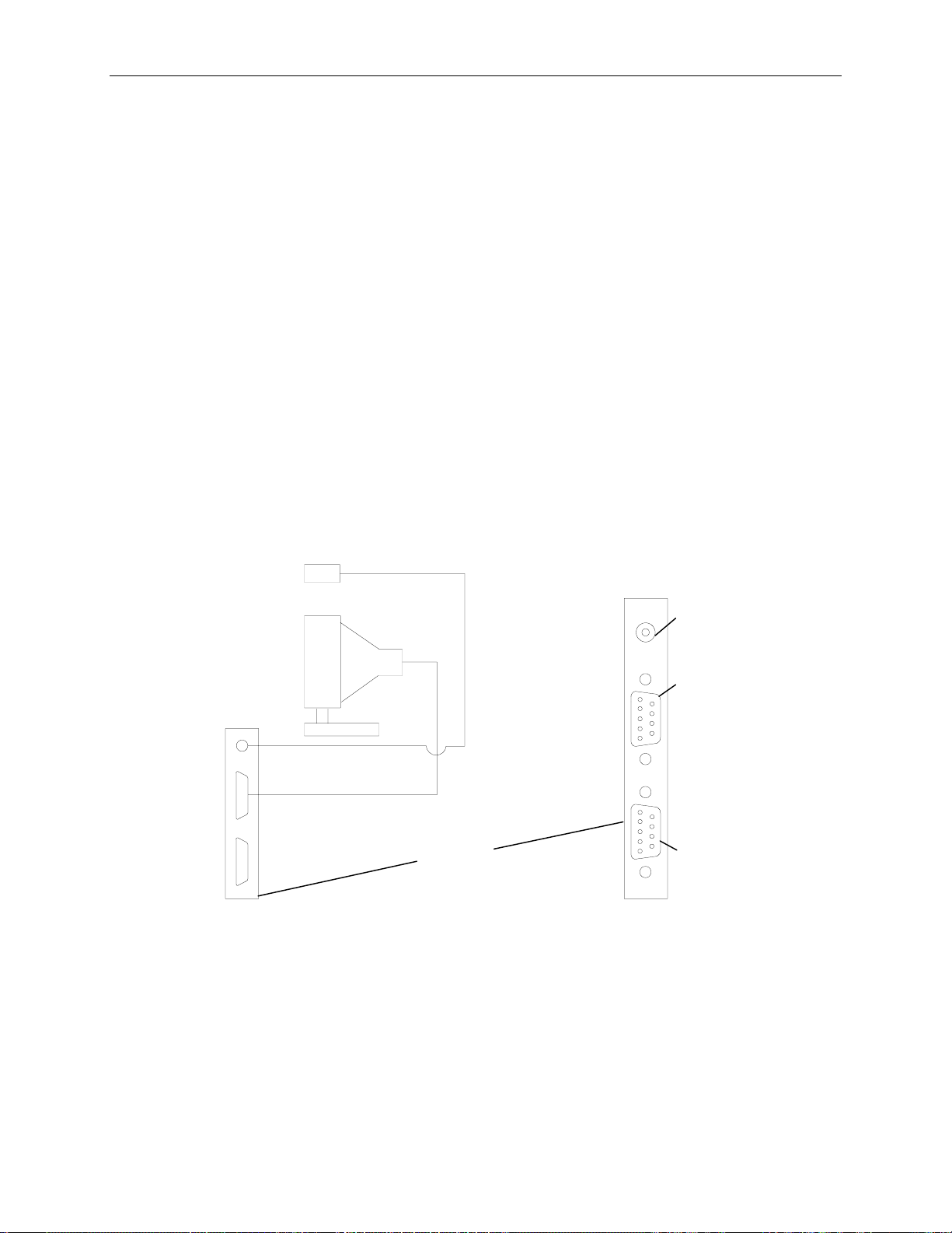
3. Connect one end of the stereo sync interface cable to the 9-pin port on the infrared transmitter.
Connect the other end (round mini-DIN) to the stereo port of the graphics board in the TDZ
workstation base unit. Refer to the following figure.
Infrared
Transmitter
Stereo Sync
Interface Cable
7
Stereo
Port
Monitor
Video Out
Video Cable
Graphics
Board in
Base Unit
Video In
(not used)
4. Connect one end of the video cable to the monitor and the other end to the Video Out port on the
graphics board.
Page 12

8
Complete the Installation
You can adjust the monitor and digitizer tables and the Cyborg chair to meet the needs of the individual
user. Refer to “Adjusting System Ergonomics” in this document. Arrange the furniture with the
monitor table centered behind and over the digitizer table. Center the Cyborg chair in front of the
digitizer table.
CAUTION Do not use auxiliary power outlets or extension cords when connecting the power cords to an AC power
wall outlet.
To connect the remaining power cords:
1. Attach one end of the power cord to the monitor. Attach the other end to an AC power wall outlet.
2. Attach one end of the power cord to the TDZ workstation. Attach the other end to an AC power
wall outlet.
3. Attach the power cord from the Altek digitizer controller to an AC power wall outlet.
4. Connect the interface PEM power cord directly to an AC power wall outlet.
To verify the installation:
1. Place the interface PEM power switch in the ON (|) position.
CAUTION After installation, the 3-position interface PEM power switch should always remain in the ON (|)
position.
2. Verify that the two-handed controller is on the active area of the digitizer table.
NOTE You should remove the two-handed controller from the digitizing surface when using the system’s
mouse. Otherwise, the cursor may snap back to the original location as defined by the two-handed
controller.
3. Verify the proper Altek digitizer controller connection to the workstation.
NOTE The system must be powered up with the two-handed controller on top of the active area (center) of the
digitizer table for proper operation.
4. Turn on power to the monitor.
5. Turn on power to the TDZ workstation base unit.
6. Verify that the green LED is lit on front of the interface PEM to ensure its power switch is in the
ON (|) position.
Maintain the Equipment
To maintain the equipment:
1. Each week, clean the bottom of the two-handed controller with a cloth or paper towel dampened
with a glass cleaning solution.
2. Periodically clean the table surface with a glass cleaning solution.
3. Clean the monitor screen as required with a glass cleaning solution.
Page 13

Activate the Stereoscopic Display
Verify that the stereo sync interface cable connects properly to the stereo port on the graphics board (in
the TDZ workstation base unit). Then, to view images in 3D, verify that the stereoscopic display is
activated as follows.
To activate the stereoscopic display:
1. From the Windows NT Start menu, select Settings/Control Panel.
2. Open Display in the Windows NT Control Panel.
3. Select Hardware Settings (tab).
4. Under Monitor Type, select the type for the monitor connected to the system.
5. Under Preferences, select Synchronized Buffer Swap to Vertical Sync.
6. Under Sceeen Options, select the appropriate monitor configuration.
7. Under Stereo, select Interlaced.
8. Select Settings (tab).
9. Under Desktop Area, select the appropriate monitor resolution. The recommended settings are
1280 x 1024 for a 21-inch monitor, 2560 x 1024 for a dual 21-inch monitor, and 1920 x 1080 for a
28-inch monitor.
9
10. Under Refresh Frequency, select 120 Hz.
11. Select OK.
12. Restart the system.
13. Use the two-handed controller and select “Reset” with any cursor button from the digitizer
command strip at the upper-left corner of tablet. This starts the two-handed controller data
tracking in Windows NT. Do this only the first time you are in Windows NT after installing the
Altek driver.
To view images in 3D:
NOTE You must be running a 3D software application to view images in 3D.
1. Activate the infrared glasses by opening the ear frames. The lenses turn black when they are on
and have a reddish-gold tint when they are off.
2. Put on the infrared glasses to view images in 3D.
When using the stereoscopic subsystem, combat the effects of stress on your eyes by periodically taking
a break. Stand up, stretch, and look away at something distant to change focal depth and to relax your
eyes.
NOTE For information on battery installation in the infrared glasses, refer to the documentation delivered with
the glasses.
Page 14

10
Customize the Screen Tracking Area
Customizing defines a small rectangle on the digitizer’s surface to represent the entire screen tracking
area. The digitizer ships preconfigured with the screen tracking area defined as the entire active
tracking area. This requires a user to move the two-handed controller across the entire length of the
digitizer’s active tracking area to move the on-screen pointer from one corner of the screen to the other.
NOTE The active tracking area is the section of the digitizer in which the two-handed controller operates. It is
identified on the digitizer surface as a rectangular outline on the mylar cover.
To select on-screen icons with less effort than using the two-handed controller, you can customize the
screen tracking area.
To customize the screen tracking area:
1. From the Windows NT Start menu, select Programs/Altek/Wintab Control Panel.
2. Double click the Customization icon.
3. Clear the Whole Tablet check box.
4. Place a data point in the grey rectangle of the Tracking Area menu.
5. Place a data point on the lower left corner of the desired tracking area in the digitizer active
tracking area.
6. Place a data point on the upper right corner of the desired tracking area in the digitizer active
tracking area.
7. Select OK to complete the operation.
Page 15

Troubleshooting the Installation
This section provides information to troubleshoot the installation of the Altek hardware and driver
software, and the JPEG hardware and driver software.
Troubleshoot the Altek Installation
Troubleshooting in Windows NT
If the two-handed controller is not tracking in Windows NT, try any of the following.
u
Verify cable connections.
u
Turn the power off, then on, to the interface PEM.
u
Disconnect and re-connect power to the Altek controller.
u
Select “Reset” from the command strip at the upper left hand corner of the tablet.
u
Reset memory to the default settings, as follows:
11
−
Load the Altek Auxiliary menu by placing the auxiliary menu on the active area of the
digitizer.
−
With any cursor button, select “Setup Menu” from the command strip.
−
First, digitize the lower left corner and then the lower right corner of the Auxillary menu using
any cursor button.
−
Select “Reset 1”, “Reset 2”, “Reset 3”, and “Reset 4” from the memory section of the
Auxillary menu. Select “Reset” from the command strip.
u
If the two-handed controller still does not track in Windows NT, try reloading the Altek driver.
Troubleshooting in MS-DOS
The diagnostics software product must be version 4.20 or later. Be aware that while using this utility,
the keyboard commands are case sensitive. You can press the F1 function key at any time to obtain
help on using the commands. Refer to the AC32 Digitizer Controller User’s Manual and Technical
Reference for detailed explanation of the available functions.
To run the Altek diagnostic:
1. Ensure the boot sequence in the system BIOS is A, C. Refer to the hardware documentation
delivered with the TDZ workstation base for instructions on changing the boot sequence, if
necessary.
2. Insert an MS-DOS boot diskette into the floppy disk drive.
3. Restart the system. When prompted for the date and time, press
values.
4. Insert the diskette containing the Altek software utility programs into the floppy disk drive.
5. At the command prompt, key in cd terminal.
6. At the command prompt, key in terminal. Ignore the data stream that displays continuously. This
is normal.
RETURN to accept the default
Page 16

12
To verify the two-handed controller buttons and X, Y data transmission:
1. Set terminal to com1, 9600, N, 8, 1, raw as shown on the screen menu, using the following
keyboard commands:
Press
Press
2. Set terminal to point mode by typing
ALT+N successively to select com1.
ALT+B successively to select the proper baud rate (9600).
SHIFT+P and then pressing ENTER. The continuous data
stream stops.
3. Verify the cable connections to the Altek digitizer controller by typing
ENTER. The following displays:
SHIFT+T and then pressing
X axis size = 93 wires
Y axis size = 63 wires
If the wire count is not displayed, then verify all cable connections to the Altek digitizer controller.
4. Display digitizer data transmission by typing
SHIFT+F and 1, and then pressing ENTER. Press any
button on the two-handed controller, and the X and Y location data begins to scroll. This indicates
the button is transmitting data. Test all of the buttons by pressing each one. The data format is of
the form
F +xxxxx +yyyyy
where F identifies the button, and where x and y are numerical values.
5. Display data transmission in a continuous data stream by typing
ENTER. The data displays continuously.
SHIFT+S and 2, then pressing
To verify the force stick functionality:
1. Set terminal to com2, 9600, N, 8, 1, raw as shown on the screen menu using the following
keyboard commands:
Press
Press
2. Display version information by typing
ALT+N successively to select com2.
ALT+B successively to select the proper baud rate (9600).
SHIFT+V and pressing ENTER. The following displays:
Intergraph Imaging Systems Stereo Cursor, Software version 1.2
PCBC080 ECO level 1
3. Activate the microprocessor to decode the force stick data by pressing
CTRL+Q. Verify force stick
operation by moving the force sticks to watch the numbers change. This indicates the force sticks
are transmitting data. The data format is of the form
H:AA X:nnn nnn Y:nnn nnn
where n is a numerical value.
The Altek digitizer controller provides you with significant capabilities for customization. It is
relatively easy to disable the Altek digitizer controller from the terminal program. Refer to the AC32
Digitizer Controller User’s Manual and Technical Reference for information on resetting memory to
the factory settings using the lowercase w1, w2, w3, w4 terminal commands.
CAUTION If resetting the digitizer to the factory settings, be careful not to use the (uppercase) W1, W2, W3, or
W4 terminal commands.
NOTE You can also reset the Altek digitizer controller to the factory settings by loading the Altek Auxiliary
Menu and selecting the Memory Reset 1-4 commands as described in “Troubleshooting in Windows
NT.”
Page 17

If only one COM port is functional, first verify proper cable connections. Second, try swapping the
RS-232 COM port cables (replace the COM 1 cable with the COM 2 cable). If this changes which
COM port is functional, replace the cable. Third, try replacing the two-handed controller or the
interface PEM.
If neither COM port is functional, verify the ribbon cable connections between the digitizer and the
Altek digitizer controller. If both COM ports still do not function, consider replacing the digitizer and
the Altek digitizer controller.
If the two-handed controller fails to operate in the Windows NT environment and the functionality of
the two-handed controller has been verified (buttons, force sticks, and X, Y data transmission) in the
terminal program, then the digitizer is functioning properly. Try the following:
Activate the two-handed controller in the Windows NT environment by selecting “Reset” from the
Altek command menu at the upper left corner of the digitizer. If this does not work, disconnect and
reconnect the Altek digitizer controller power cord, and toggle the interface PEM power switch. If this
fails, re-install the Altek driver.
Troubleshoot the JPEG Installation
The diagnostics software product must be version 01.00.00.02 or later.
13
To run the JPEG diagnostic:
1. Ensure the boot sequence in the system BIOS is A, C. Refer to the hardware documentation
delivered with the TDZ workstation base for instructions on changing the boot sequence, if
necessary.
2. Insert an MS-DOS boot diskette into the floppy disk drive.
3. Restart the system. When prompted for the date and time, press
values.
4. Insert the diskette containing the JPEG diagnostic into the floppy disk drive.
5. At the command prompt, key in vediag -I (capital I). Wait approximately 20 seconds, and the
following prompt displays:
VEDIAG>
6. Key in jp_tests to access the tests menu. A column indicates the tests are disabled.
7. Key in 1 2 3 4 5 6 7 c to enable and start the required tests.
8. After completing at least one loop, press
9. If the diagnostics pass, the following message displays
Tests Complete Loops Completed:
where n is a numerical value.
If a diagnostic test fails, contact the Customer Response Center at 1-800-633-7248.
ESC to stop the tests.
n
Errors: 0
RETURN to accept the default
10. Remove the diskette containing the diagnostic software from the floppy disk drive.
11. Restart the system.
Page 18

14
Re-Installing the Software
This section describes how to re-install the Altek and StudioZ Producer driver software, and how to
activate the stereoscopic display.
Install the Altek Driver
The Altek driver software controls the operation of the Altek digitizer.
To install the Altek driver:
1. Start the TDZ workstation base unit and monitor, and log on to Windows NT.
2. Insert the diskette containing the Altek driver in the system’s floppy disk drive.
3. From the Windows NT Start menu, select Run.
4. Key in the path to the Install program on the diskette (typically a:/install.bat).
5. Select Continue to install the Wintab driver.
6. Select Continue to accept the default Com1 and device size.
7. Select Yes to confirm the installation, and then select OK after successful installation. The
following appears:
Intergraph hardware requires a tablet size of 34 inches by 22 inches.
The necessary changes will be made to the registry now.
8. Select OK to accept the default values.
9. From the Start menu, select Settings/Control Panel/Ports.
10. In the Ports dialog, select Add.
11. In the Advanced Settings for New Port dialog, select COM Port Number 1.
12. Select OK to accept the default values; then, select Don’t Restart Now.
13. In the Ports dialog, select Add.
14. In the Advanced Settings for New Port dialog, select COM Port Number 2.
15. Select OK to accept the default values; then, select Restart Now.
16. On startup, Windows NT attempts to load a serial ball point driver (which does not exist) for the
COM2 port. Exit from the Files Needed dialog, and proceed with customizing the Altek driver.
To customize the Altek driver:
1. From the Start menu, select Programs/Altek/Wintab Control Panel.
2. Under Features/Cursor Type, select 16-button cursor; then select OK.
3. Under Customization, de-select the default button assignments. Set button 7 to left click. Set
button 8 to right click. Set all other buttons to none; then select OK.
NOTE Button 7 corresponds to the index finger of the right hand resting on the two-handed controller. The
buttons range from 1 on the far left (not counting the force sticks) to 10 on the far right.
Page 19

If this is a first-time setup, install the StudioZ Producer driver software and activate the stereoscopic
display.
Install the StudioZ Producer Driver
The StudioZ Producer driver controls the operation of the StudioZ Producer JPEG board.
NOTE The JPEG board is factory-installed in the TDZ workstation base unit.
To install the StudioZ Producer driver:
1. Insert the diskette containing the StudioZ Producer driver in the system’s floppy disk drive.
2. From the Windows NT Start menu, select Run.
3. Key in the path to the Setup program on the diskette (typically a:/setup).
4. Select OK.
5. When the Welcome dialog displays, select Continue.
6. When the Destination Directory dialog displays, select Continue to accept the default installation
path (
C:\WIN32APP\INGR\IVEDRV).
15
7. At the Video Board Selection dialog, select No.
8. When the Misc Configuration Items dialog displays, select Continue to take the default settings.
9. When the Installation Successful dialog displays, select OK.
Changes will take effect after restarting the system. If this is a first-time setup, activate the stereoscopic
display before restarting the system.
Page 20

16
Understanding the JPEG System
The StudioZ Producer JPEG Compression/Decompression system provides the capability to compress
and decompress images. It is a single Peripheral Component Interface (PCI) board that accelerates the
compression and decompression operations in a hardware engine.
The following figure represents the JPEG Compression/Decompression board.
Digital Video Connector
JPEG
Compression/
Decompression
Processor
The JPEG system provides direct memory access capability to allow compression and decompression
to occur with minimal host CPU intervention. JPEG compression works on each image individually.
Images (raster data blocks) in system memory can be compressed and then stored to system memory.
Compressed images can also be decompressed with both the source and destination being system
memory. Images must comprise an integer multiple of 8 x 8 pixel blocks.
Quality of a reconstructed image is a function of how much the image was compressed. The video
quality factor (controlled by StudioZ Producer) and the contents of the compressed image determine
the compression ratio. Compression ratio is the size (in bytes) of the original image divided by the
compressed image. The higher the video quality factor, the higher the quality of the image and the
lower the compression ratio. Higher video quality also requires larger disk space. The lower the video
quality factor, the greater the compression ratio and the more likely an image contains visible artifacts
of the compression process.
The compression algorithm used by the JPEG board has loss (not a bit-for-bit copy of the original), but
the algorithm preserves information needed to reconstruct a copy that is visually faithful to the original.
Page 21

Adjusting System Ergonomics
This section provides human-factors (ergonomic) recommendations you should follow when setting up
and using the ImageStation Z system. Perform the following steps in the order presented.
Adjust the Cyborg Chair
Use the reference material provided with the Cyborg chair to make the following adjustments.
To adjust the chair:
1. Adjust the seat height so that your feet are flat on the floor and your knees are bent approximately
90 degrees.
17
NOTE If needed, use a footrest to allow feet to rest on a flat surface. Do not use the table as a footrest.
CAUTION The digitizer table work surface is a non-load bearing surface. Damage to sensitive parts may occur if
used for purposes other than intended. Operator injury or mechanical damage could occur.
2. Adjust the seat to distribute the weight of the upper body comfortably over the seat. The seat
should be nearly level.
3. Adjust the height and angle of the backrest to maintain contact with the lumbar area of the back
when you are sitting in a normal working posture.
4. Adjust the height of the armrests to support the arms when your shoulders are relaxed and your
upper arms are at your side.
Page 22

18
Adjust the Digitizer Table
Adjust the height of the digitizer table so that your arms are comfortably at your side when using the
two-handed controller or keyboard.
Your elbows should be bent at approximately 90 degrees when your hands are resting on the twohanded controller or at the keyboard. If the table is at the lowest setting, you may need to raise the
chair height to place your hands at a proper height. A footrest may be required if your feet do not rest
flat on the floor.
To adjust the digitizer table:
1. Move the digitizer table out from under the monitor table when using the entire digitizing area.
2. Lock the casters on the digitizer table when in use to prevent it from moving unintentionally.
Adjust the Monitor Table
The monitor table should be centered along the back edge of the digitizer table so that the monitor
screen will be directly in front of you.
Adjust the height of the monitor table so that the center of the monitor screen is slightly below eye
level.
Adjust the Monitor Position
The monitor should be placed on the monitor table. The monitor base should be centered on the table
top to evenly distribute the weight of the monitor on the table. This position allows enough room for
the placement of the keyboard in front of the monitor, if desired.
NOTE Avoid placing the monitor so that it reflects glare from room lights.
Adjust the Keyboard Position
The keyboard can be placed in any position on the digitizer table, or on the front of the monitor table,
according to your preference.
To use the keyboard:
1. For periods of infrequent keyboard input, place the keyboard on the front edge of the monitor table
in front of the monitor.
2. For periods of frequent keyboard input, place the keyboard on the digitizer table in front of you.
NOTE When not in use, the keyboard can be moved to either side of the digitizer table.
Page 23

Adjust the Two-Handed Controller
The two-handed controller uses a standard bobbin, ten buttons, and two force-operated joysticks called
force sticks. The ten buttons are application-specific. They are mapped and specified within the
application software.
CAUTION Exerting excessive force on the buttons and force sticks can cause fatigue or may cause them to
break.
The thumb lever force sticks are sensitive to force rather than to displacement, and require minimal
force to operate. Over-straining the force sticks will not speed performance.
The ten buttons require minimal force and should be pressed until a click is heard or felt. Excessive
force will cause fatigue.
10 9 8 7 4 3 2 1
19
5 6
Force
Stick
Bobbin
Two-Handed Controller
Adjust the Stereoscopic Glasses
The infrared emitter refreshes the lenses in the stereoscopic glasses at 60 Hz, in exact synchronization
with the images displayed on the monitor. Please take time to read the documentation supplied with the
glasses. It contains important information about use and care of the glasses.
NOTE Consult the
and replacing the batteries.
Crystal Eyes Stereoscopic Glasses User’s Manual
for information on cleaning the glasses
Page 24

20
 Loading...