

Page 1

GT RAX Systems
System Reference
April 1999
D1AA00100
Page 2

Copyright
1999 Intergraph Computer Systems. All rights reserved. This document contains information protected by copyright, trade secret, and
trademark law. This document may not, in whole or in part, be reproduced in any form or by any means, or be used to make any derivative
work, without written consent from Intergraph Computer Systems.
Use, duplication, or disclosure by the United States Government is subject to restrictions as set forth in subdivision (c)(1)(ii) of the rights in
technical data and computer software clause at DFARS 252.227-7013. Unpublished rights are reserved under the copyright laws of the
United States.
Intergraph Computer Systems, Huntsville AL 35894-0001
Notice
Information in this document is subject to change without notice and should not be considered a commitment by Intergraph Computer
Systems. Intergraph Computer Systems shall not be liable for technical or editorial errors in, or omissions from, this document. Intergraph
Computer Systems shall not be liable for incidental or consequential damages resulting from the furnishing or use of this document.
All warranties given by Intergraph Computer Systems about equipment or software are set forth in your purchase contract. Nothing stated in,
or implied by, this document or its contents shall be considered or deemed a modification or amendment of such warranties.
Trademarks
Intergraph Computer Systems and the Intergraph Computer Systems logo are registered trademarks of Intergraph Computer Systems.
StudioZ and ViZ RAX are trademarks of Intergraph Computer Systems. Other brands and product names are trademarks of their respective
owners.
FCC/DOC Compliance
This equipment has been tested and found to comply with the limits for a Class B digital device, pursuant to part 15 of the FCC Rules. These
limits are designed to provide reasonable protection against harmful interference when the equipment is operated in a commercial
environment. This equipment generates, uses, and can radiate radio frequency energy. If the equipment is not installed and used in
accordance with the instruction manual, it may cause harmful interference to radio communications.
Operation of this equipment in a residential area is likely to cause harmful interference in which case the user will be required to correct the
interference at his own expense.
Changes or modifications made to the system that are not approved by the party responsible for compliance could void the user’s authority to
operate the equipment.
This Class B digital apparatus meets all requirements of the Canadian Interference-Causing Equipment Regulations. Cet appareil numérique
de la classe B respecte toutes les exigencies du Règlement sur le materi él brouilleur du Canada.
Warnings
The service and upgrade instructions should be performed by qualified personnel only. Qualified personnel do not have to be Intergraph
service personnel. Qualified personnal can include those who are familiar with servicing computers, can follow instructions in a manual to
service equipment, and can do so without harm to themselves or damage to the equipment.
Changes or modifications made to the system that are not approved by the party responsible for compliance could void the user's authority to
operate the equipment.
To reduce the risk of electrical shock, do not attempt to open the equipment unless instructed. Do not use a tool for purposes othe r than
instructed.
There is a danger of explosion if the battery is incorrectly replaced. Replace the battery only with the same or equivalent type as
recommended by the manufacturer. Dispose of used batteries according to the manufacturer's instructions.
Notes
Read all operating instructions before using this device. Keep these instructions for future reference. Follow all warnings on the device or in
the operating instructions. This device is designed and manufactured to comply with approved safety standards for information processing
and business equipment.
Page 3

Contents
Preface........................................................................................................................................... vii
About This Document....................................................................................................................vii
Document Conventions .................................................................................................................. vii
Customer Support.......................................................................................................................... viii
1 Accessing the Components.......................................................................................................... 1
Before You Begin............................................................................................................................. 2
Tools................................................................................................................................................. 2
Avoiding Electrostatic Discharge..................................................................................................... 2
Opening the Base Unit...................................................................................................................... 3
Opening and Closing the Face Panel................................................................................................ 3
Closing the Base Unit....................................................................................................................... 4
System Illustrations .......................................................................................................................... 5
2 Servicing the System.................................................................................................................... 7
Before You Begin............................................................................................................................. 8
Base Unit Components..................................................................................................................... 8
Disk Drives....................................................................................................................................... 9
Disk Drive Bay............................................................................................................................... 14
SAF-TE Card.................................................................................................................................. 16
Power Supply..................................................................................................................................17
Processor Modules ......................................................................................................................... 19
Heat-Sink Mounting Brackets ........................................................................................................ 20
Retention Modules.......................................................................................................................... 21
Dual Inline Memory Modules......................................................................................................... 22
System Board..................................................................................................................................23
Expansion Cards............................................................................................................................. 24
Chassis Fan..................................................................................................................................... 24
Disk Drive Bay Fans.......................................................................................................................26
CMOS/Clock Lithium Battery........................................................................................................ 26
LEDs, Power, and Reset Switches.................................................................................................. 27
iii
Hardware and Software Support Services.......................................................................viii
World Wide Web............................................................................................................ viii
Intergraph Bulletin Board Service...................................................................................viii
Telephone.......................................................................................................................... ix
More Support Options....................................................................................................... ix
System Disk Drive.............................................................................................................. 9
CD-ROM Drive................................................................................................................ 10
Floppy Disk Drive............................................................................................................ 12
Removable Disk Drives....................................................................................................13
3 Upgrading the System............................................................................................................... 31
Before You Begin........................................................................................................................... 32
Adding Memory............................................................................................................................. 32
Upgrading Processors..................................................................................................................... 34
Page 4

iv
Adding Expansion Cards................................................................................................................ 34
Slot Locations................................................................................................................... 35
Installing Expansion Cards............................................................................................... 35
Expansion Cards with PCI-to-PCI Bridges...................................................................... 36
Assigning System Resources............................................................................................ 36
Adding Removable Disk Drives..................................................................................................... 37
Adding an Internal SCSI Peripheral Device................................................................................... 37
Adding External SCSI Peripheral Devices..................................................................................... 40
SCSI Cable Lengths and Device Speeds.......................................................................... 40
SCSI Cable Quality.......................................................................................................... 41
SCSI IDs .......................................................................................................................... 41
SCSI Termination for External Devices........................................................................... 41
Connecting an External SCSI Drive................................................................................. 41
Changing SCSI Controller or Device Settings................................................................. 42
4 System Board............................................................................................................................. 43
Slots and Sockets............................................................................................................................ 44
Connectors and Components.......................................................................................................... 45
Connectors...................................................................................................................................... 46
Jumper Functions............................................................................................................................ 49
Jumper Connectors......................................................................................................................... 50
CPU Frequency................................................................................................................ 50
Host Bus Frequency......................................................................................................... 51
External Ports................................................................................................................................. 52
Sound Processor............................................................................................................................. 58
5 System Resources....................................................................................................................... 59
Available IRQs............................................................................................................................... 60
Freeing IRQs .................................................................................................................................. 60
PCI Devices.................................................................................................................................... 60
PCI to ISA Bus Interrupt Mapping................................................................................................. 60
Configuration Data......................................................................................................................... 61
Interrupt Requests (IRQs)................................................................................................ 61
DMA Channels................................................................................................................. 62
Input/Output Addresses.................................................................................................... 62
Memory Address Map...................................................................................................... 63
6 System Hardware...................................................................................................................... 65
Hardware Overview........................................................................................................................ 66
Functional Diagram........................................................................................................................ 67
System Board Block Diagram........................................................................................................ 68
SCSI Cable Routing........................................................................................................................69
Disk Drive Bay............................................................................................................................... 70
Cable Routing and Pinouts............................................................................................... 70
Jumper Settings................................................................................................................ 72
Removable Disk Drive LEDs........................................................................................... 72
Page 5

Power Supply..................................................................................................................................73
Chassis Cooling Fans...................................................................................................................... 74
Disk Drive Bay Cooling Fans ......................................................................................................... 75
Hardware Monitoring and Power Management.............................................................................. 75
7 Peripheral Devices..................................................................................................................... 77
Internal Peripheral Device Cables.................................................................................................. 78
Floppy Disk Drive Cable.................................................................................................. 78
Disk Drive Bay SCSI Cable............................................................................................. 78
Wide Ultra2 SCSI Cable.................................................................................................. 79
Narrow Ultra SCSI Cable................................................................................................. 79
Peripheral Device Configuration.................................................................................................... 80
Floppy Disk Drive............................................................................................................ 80
SCSI CD-ROM Drive...................................................................................................... 80
SCSI Disk Drives............................................................................................................. 81
8 System Information................................................................................................................... 83
Specifications ................................................................................................................................. 84
System Configuration Summary..................................................................................................... 84
System Board..................................................................................................................................85
v
Page 6

vi
Page 7

Preface
This System Reference document describes how to service and upgrade your Intergraph Computer
Systems rack-mount GT RAX System. This document supports the following RAX systems:
♦ StudioZ GT RAX for SOFTIMAGE|DS
♦ StudioZ GT for SynaFlex
♦ ViZRAX-GT
About This Document
This System Reference document is organized as follows:
♦ Chapter 1, “Accessing the Components,” describes how to open and close the base unit and
how to access internal system components.
♦ Chapter 2, “Servicing the System,” describes how to replace standard system components.
♦ Chapter 3, “Upgrading the System,” describes how to add components to the system.
♦ Chapter 4, “System Board,” provides detailed information on the system board and its
components.
vii
♦ Chapter 5, “System Resources,” provides detailed information on system resources.
♦ Chapter 6, “System Hardware,” provides a system hardware overview and technical
information on system components.
♦ Chapter 7, “Peripheral Devices,” provides information on cabling and configuration o f
standard system peripherals.
♦ Chapter 8, “System Information,” provides system specifications and other general technical
information.
Document Conventions
Bold
Italic Variable values that you supply, or cross-references.
Monospace
SMALL CAPS Key names on the keyboard ( s uch as D, ALT, or F3) and names of files and
CTRL+D Press a key while simultaneously pressing another key; for example, press CTRL and
Commands, words, or characters that you key in literally.
Output displayed on the screen.
directories. You can type filenames and directory names in the dialog boxes or the
command line in lowercase unless directed otherwise.
D simultaneously.
Page 8

viii
Customer Support
Intergraph Computer Systems offers an assortment of customer support options.
Hardware and Software Support Services
Intergraph Computer Systems provides a variety of hardware services for Intergraph and thirdparty equipment. Services include warranty upgrades, repair depot service, on-site hardware
maintenance, system administration, and network co nsulting. Hardware purchased from Intergraph
Computer Systems includes a factory warranty ranging from 30 days to three years. A detailed
warranty description is available on the World Wide Web; see the Support pages at
http://www.intergraph.com/ics.
Intergraph Computer Systems provides complimentary software support for 30 or 90 days
following shipment of a hardware or software product. This includes World Wide Web access,
Intergraph Bulletin Board Service access, and telephone (Help Desk) support. At the end of the
complimentary support period, you can purchase other levels of software support.
World Wide Web
You can visit Intergraph Computer Systems on the World Wide Web at
http://www.intergraph.com/ics. On these pages, you can get news and product information,
technical support information, software updates and fixes, and more.
Intergraph Bulletin Board Service
On the Intergraph Bulletin Board Service (IBBS), you can get technical support information,
software updates and fixes, and more.
NOTE Most of the system software for your RAX system can be found in the TDZ 2000 GT1
area of the IBBS. Additional software can be found in the Digital Media area of the
IBBS.
To connect to the IBBS:
1. Set your system’s communications protocol for eight (8) data bits, no parity, one (1) stop bit,
and any baud rate up to 14,400.
2. Using a modem, call 1-256-730-8786. Outside the United States, call one of the mirror sites
listed on World Wide Web; see the Software Support pages at http://www.intergraph.com.
3. At the login prompt, key in your user ID, or new if you have not used the IBBS befo re.
4. Follow the menus to find what you need.
Page 9

If you have trouble conne cting to or using the IBBS , call the Customer Response Center at
1-800-633-7248 (product entry IBBS) or leave a message for the IBBS System Operator at
1-256-730-1413.
Telephone
To get customer support by telephone:
♦ In the United States, call 1-800-633-7248 between the hours of 7:00 a.m. and 7:00 p.m.
♦ Outside the United States, contact your local Intergraph Computer Systems subsidiary or
Have the following information available when you call:
♦ Your service number, which identifies your site to Intergraph Computer Systems. You use
♦ Your Customer Personal Identification Number (CPIN). You get a CPIN the first time you
♦ The product’s name or model number.
ix
Central Time, Monday through Friday (except holidays).
distributor.
your service number for warranty or maintena nce calls.
call the Customer Response Center; it is associated with your service number for future call
logging.
♦ The product’s serial number. Software product serial numbers are included in the product
packaging. Hardware product serial numbers are on a sticker affixed to the product.
♦ Your name and telephone number.
♦ A brief description of the question or problem.
More Support Options
To get information on more customer support options:
♦ Visit the Support pages on the World Wide Web at http://www.intergraph.com/ics.
♦ For hardware support questions in the United States, call 1-800-763-0242.
♦ For software support questions in the United States, call 1-800-345-4856.
♦ Outside the United States, contact your local Intergraph Computer Systems subsidiary or
distributor.
Page 10

x
Page 11

1 Accessing the Components
This chapter describes how to access the internal components of the system so you can service and
upgrade your GT RAX system. This chapter also lists tools and describes methods for avoiding
electrostatic discharge, removing and replacing cover panels, and accessing components.
Before You Begin............................................................................................................................. 2
Tools................................................................................................................................................. 2
Avoiding Electrostatic Discharge..................................................................................................... 2
Opening the Base Unit...................................................................................................................... 3
Opening and Closing the Face Panel................................................................................................ 3
Closing the Base Unit....................................................................................................................... 4
System Illustrations .......................................................................................................................... 5
1
Page 12

2
Before You Begin
WARNING Disconnect the system and peripheral devices from AC power before servicing
internal components! Failure to remove AC power may result in equipment
damage or personal injury. The GT RAX system is always on when connected
to AC power.
WARNING Follow all warnings and cautions in the servicing instructions. If you fail to
follow documented procedures, personal injury and damage to equipment can
result.
CAUTION Use an antistatic wrist strap for all servicing procedures to avoid the possibility of
electrostatic discharge.
“Right side” and “left side” are as seen fr om the front of the unit.
Tools
You will need the following tools to service the system:
♦ Antistatic wrist strap
♦ Quarter-inch nutdriver
♦ No. 1 and No. 2 Phillips screwdrivers
♦ Three-sixteenth-inch or 5 mm nutdriver
♦ Five-sixteenth-inch or 8 mm nutdriver
♦ Small single-slot screwdriver
Avoiding Electrostatic Discharge
Sensitive components inside the base unit can be damaged by static electricity. To protect against
this possibility, take the following precautions when working with internal components.
♦ Unplug the unit from AC power before servicing any electronic component inside the chassis.
♦ Touch the bare metal of the base unit to ensure the base unit and your body are at the same
electric potential.
♦ Handle all printed circuit boards as little as possible and by the edges only. Leave new parts
in their protective packaging until you install them.
♦ Use a disposable or reusable antistatic wrist strap when servicing or upgrading the system.
Once a disposable wrist strap is used, it cannot be used again.
Page 13
♦ Attach an antistatic wrist strap to any bare metal part of the base unit. The metal conductor in
the elastic sleeve of reusable antistatic straps must contact bare skin.
Opening the Base Unit
WARNING Before you open the base unit, shut down the system, disconnect the system
from AC power, and turn off power to external devices (including peripheral
devices and the monitor). Use caution to avoid injury when removing covers
and other hardware.
CAUTION Ensure the stabilizers of the rack in which the system is mounted are fully extended.
To open the base unit:
1. Remove the screws that secure the handles to the rack.
2. Disconnect all cables including the power cable, monitor, and all peripheral cables from the
back of the unit.
3. Slide the base unit out of the rack until it locks in the extended position.
4. Remove and retain the two screws that secure the top cover to the chassis: one each on the
upper left and upper right corners of the back of the chassis.
3
5. Slide the top cover back and lift it off.
6. Attach the grounding clip from the antistatic wrist strap to bare metal.
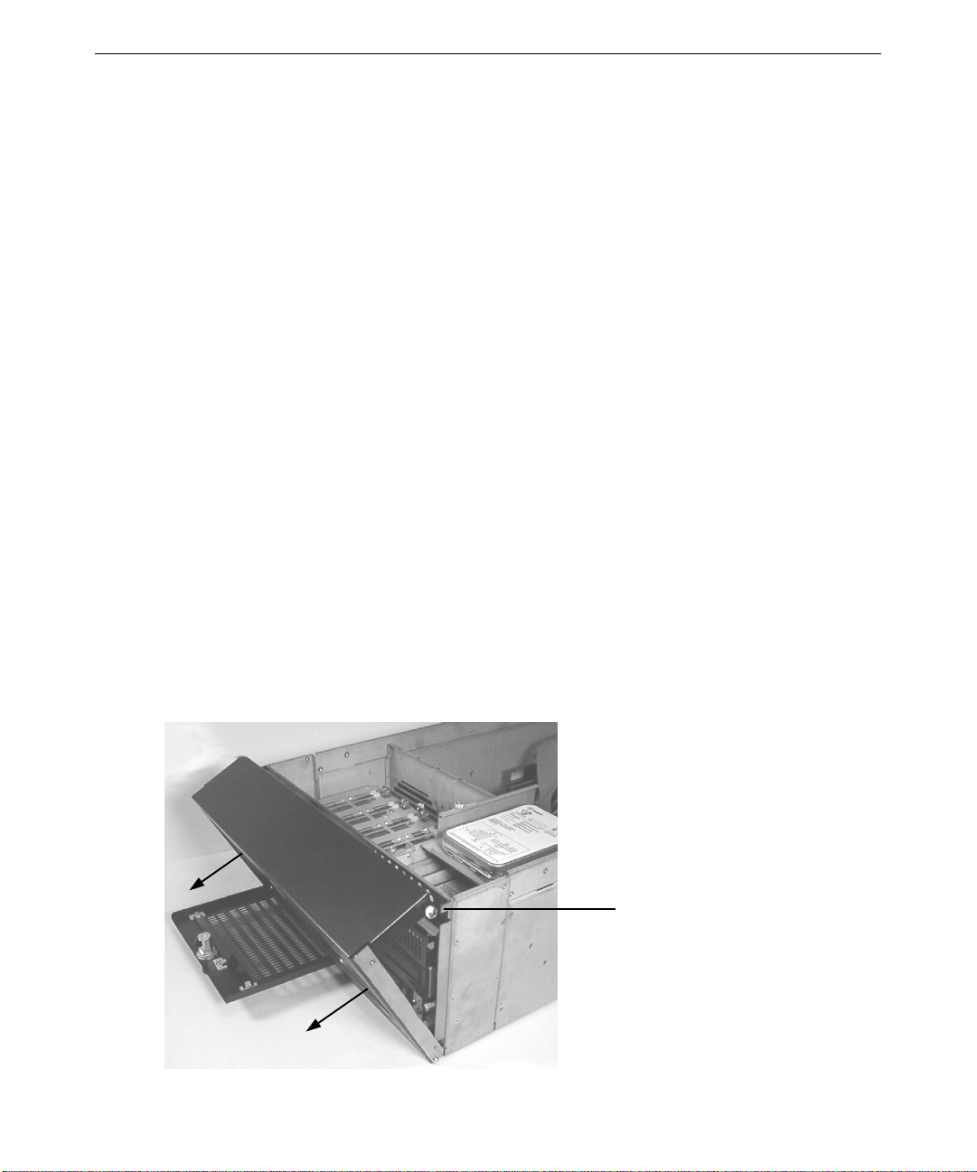
Opening and Closing the Face Panel
Face Panel Thumbscrew
(one on each side)
Page 14

4
To open the face panel:
1. Open the disk drive bay door.
2. Loosen the two thumbscrews that secure the face panel to the base unit (on the upper right and
upper left corners of the face panel). See the following figure.
3. Pull the face panel toward you to open it. The face panel swings down on hinges attached to
the lower corners of the base unit. See the following figure.
To close the face panel:
1. Lift the face panel upward and push it onto the base unit.
2. Secure the face panel to the base unit by tightening the two thumbscrews.
3. Close the disk drive bay door.
Closing the Base Unit
CAUTION After servicing or upgrading the system, always replace the covers that were
removed. The covers ensure the system maintains proper air flow, so internal
components do not overheat and fail. The covers also ensure that electromagnetic
interference (EMI) emissions remain below the standard requirements.
To close the base unit:
1. Remove the antistatic wrist strap from the base unit.
2. Replace the top cover.
3. Secure the top cover to the base unit with the screws retained earlier.
4. Slide the base unit into the rack.
5. Secure the base unit to the rack by replacing the screws attaching the handles to the rack.
6. Reconnect all cables including the power cable, monitor, and peripheral cables to the back of
the system.
Page 15
System Illustrations
The following illustrations show both external and internal views of the system.
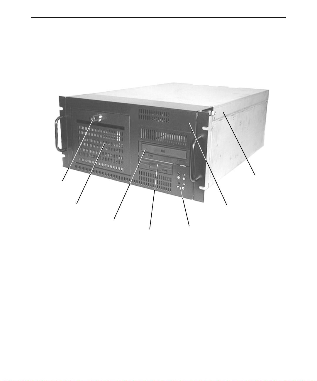
This front, right view shows the system with all covers in place .
5
Disk Drive Bay
Door Lock
Disk Drive Bay
CD-ROM Drive
Floppy Disk Drive
Top Cover
Face Panel
System LEDs and
Power/Reset Switches
Page 16
6
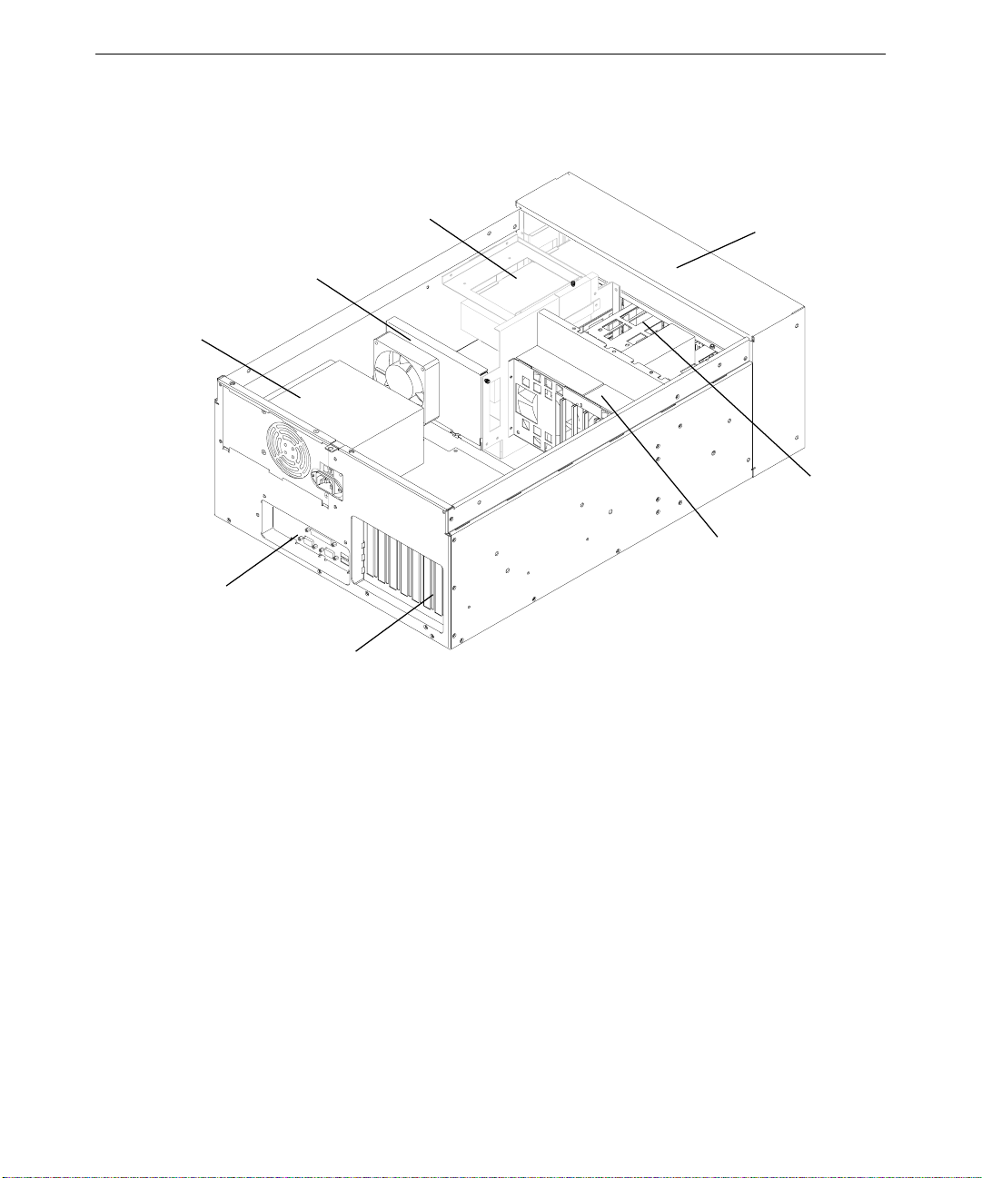
This back, right view shows major internal parts of the system without covers, cables, system
board, and option cards.
Power Supply
Chassis Fan/
Mounting
Plate
Peripheral
Device Bay
Face Panel
Disk Drive Bay
Disk Drive Bay
Fans
Input/Output Panel
Expansion Slots
Page 17

2 Servicing the System
This chapter describes how to replace the standard parts inside your GT RAX system.
Before You Begin............................................................................................................................. 8
Base Unit Components..................................................................................................................... 8
Disk Drives....................................................................................................................................... 9
System Disk Drive.............................................................................................................. 9
CD-ROM Drive................................................................................................................ 10
Floppy Disk Drive............................................................................................................ 12
Removable Disk Drives....................................................................................................13
Disk Drive Bay............................................................................................................................... 14
SAF-TE Card.................................................................................................................................. 16
Power Supply..................................................................................................................................17
Processor Modules ......................................................................................................................... 19
Heat-Sink Mounting Brackets ........................................................................................................ 20
Retention Modules.......................................................................................................................... 21
Dual Inline Memory Modules......................................................................................................... 22
System Board..................................................................................................................................23
Expansion Cards............................................................................................................................. 24
Chassis Fan..................................................................................................................................... 24
Disk Drive Bay Fans.......................................................................................................................26
CMOS/Clock Lithium Battery........................................................................................................ 26
LEDs, Power, and Reset Switches.................................................................................................. 27
7
Page 18
8
Before You Begin
WARNING Disconnect the system and peripheral devices from AC power before servicing
internal components! Failure to remove AC power may result in equipment
damage or personal injury. The GT RAX system is always on when connected
to AC power.
WARNING There is a danger of explosion if the battery is incorrectly replaced.
WARNING Follow all warnings and cautions in the servicing instructions. If you fail to
follow documented procedures, personal injury and damage to equipment can
result.
CAUTION Use an antistatic wrist strap for all servicing procedures to avoid the possibility of
electrostatic discharge.
CAUTION Do not overtighten screws and other fasteners to avoid damaging threads.
CAUTION Follow all warnings and cautions in these servicing instructions. If you fail to follow
documented, approved procedures, personal injury or damage to equipment can
result.
See Chapter 1, “Accessing the Components,” for details on opening the system and protecting
against electrostatic discharge. These procedures assume you have removed the cover from the
system. “Right side” and “left side” are as seen from the front of the unit. After servicing the
system, replace panels as described in Chapter 1, “Accessing the Components.”
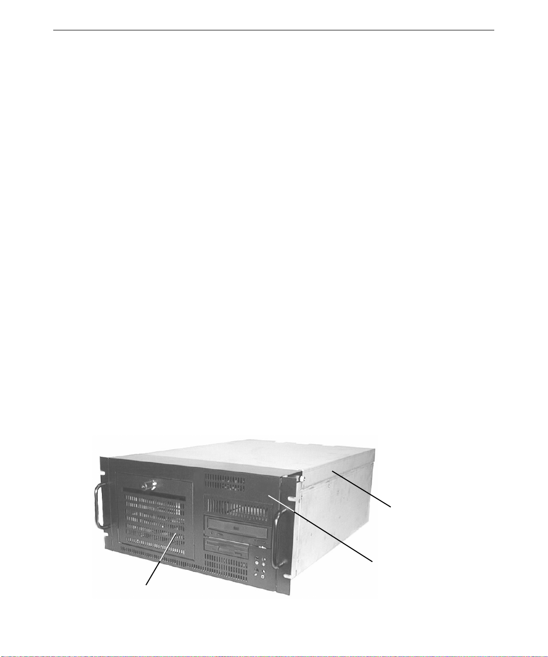
Base Unit Components
The following figur e shows the base unit components that can be replaced:
Disk Drive
Bay Door
Top Cover
Face Panel
Page 19

To replace the disk drive bay door, you must first remove the top cover and open the face panel.
To replace the face panel, you must remove the top cover and the disk drive bay door.
To replace the top cover:
1. Remove the top cover. See Chapter 1, “Accessing the Components,” for details.
2. Install the new cover.
To replace the disk drive bay door:
1. Open the face panel. See Chapter 1, “Accessing the Components,” for details.
2. Remove the two hinge screws attaching the door to the face panel.
3. Remove the door.
4. Position the new door so that the screw holes on the door are aligned with holes in the face
panel.
5. Replace the two hinge screws, ensuring that the hinge screws are equally tightened. This will
ensure that the door is centered properly.
To replace the face panel:
1. Remove the disk drive bay door from the old face panel as described previously.
9
2. Install the disk drive bay door in the new face panel as described previously.
3. Remove the old face panel by removing the two shoulder screws at the bottom left and right
corners of the face panel.
4. Align the bottom of the new face panel with the front of the unit, and reattach the two shoulder
screws from step 3.
5. Close the new face panel. See Chapter 1, “Accessing the Components,” for details.
Disk Drives
This section explains how to replace the CD-ROM drive and the various disk drives in the system.
See Chapter 7, “Peripherals,” for details on drive configuration and cables.
System Disk Drive
The system disk drive is located in the uppermost part of the peripheral device bay, above the
CD-ROM and floppy disk drives, as shown in the following figure.
Page 20
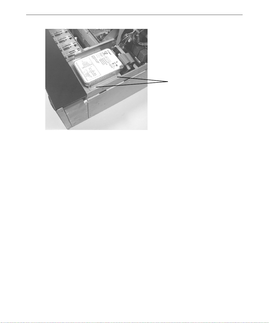
10
Nuts (two on each side)
To replace the system disk drive:
1. Disconnect the power cable and SCSI cable from the disk drive.
2. Remove the four nuts (two on each side) from the vertical screws on each side of the disk
drive, and lift the disk drive out of the chassis.
3. Remove the brackets from the replaced disk drive and secure them to the new disk drive.
WARNING Handle the disk drive carefully to prevent failure and voiding the warranty for
4. Replace the new disk drive in the chassis and secure it with the four nuts removed previously.
5. Connect the power cable and SCSI cable to the disk drive.
You will need to reinstall the operating system and associated system software on the new system
disk drive. See System Setup for more information.
CD-ROM Drive
To replace the CD-ROM drive:
1. For ease of access, remove the chassis fan as described later in “Chassis Fan.”
the drive.
Page 21
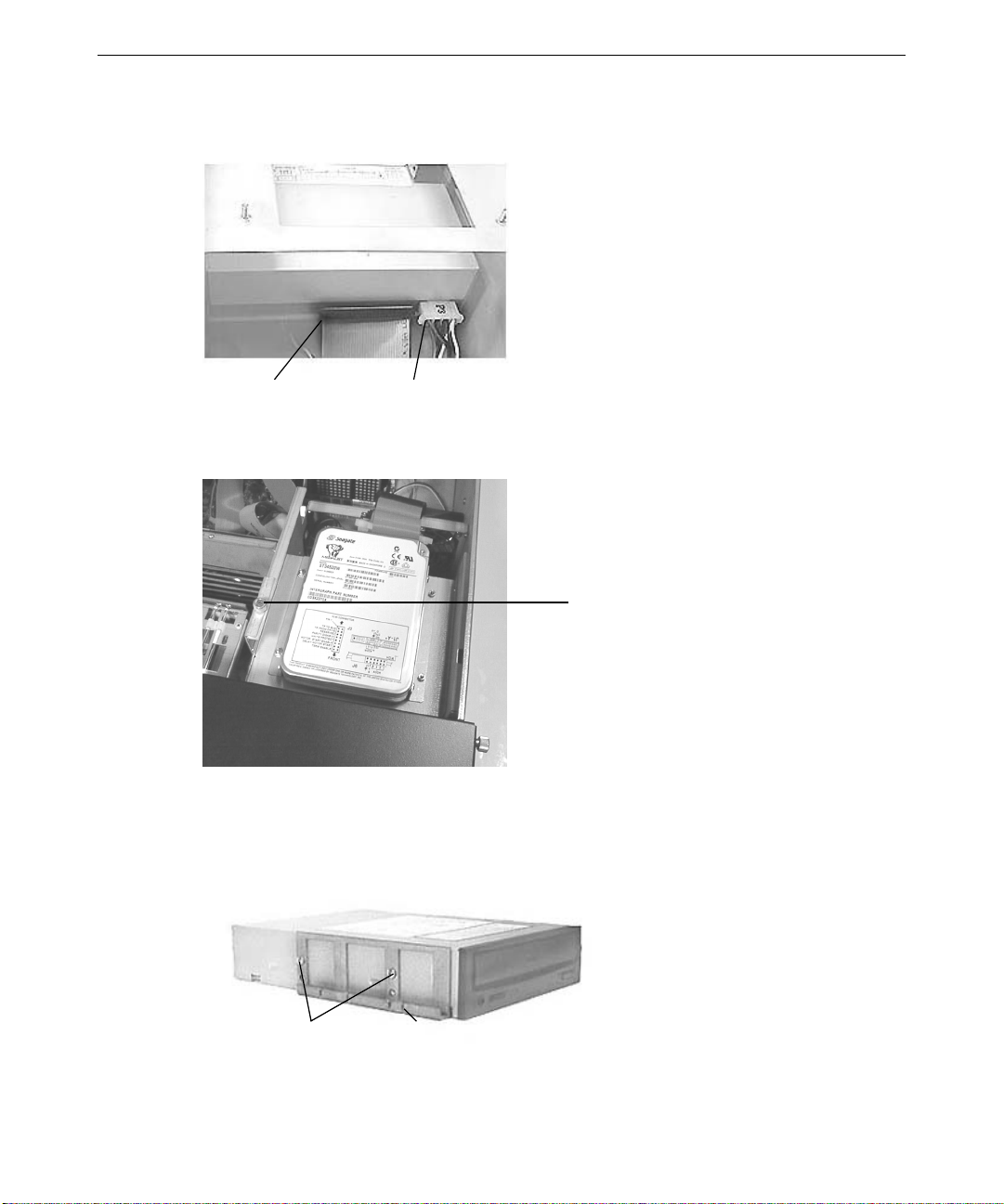
11
2. Disconnect the power cable and SCSI cable from the CD-ROM drive. Note the position of the
red stripe on the SCSI cable.
Data Cable Power Connector
3. Loosen the thumbscrew on the front-most locking plate on the top left side of the peripheral
device bay.
Locking Plate
Thumbscrew
4. Lift and hold the locking plate.
5. From inside the chassis, push the back of the CD-ROM until the bezel clears the front of the
chassis, then slide the device out.
6. Remove the mounting guides from the right and left sides of the CD-ROM drive.
Mounting Guide
Screws
Slot for Drive
Placement
Page 22
12
7. Note the jumper settings on the back of the CD-ROM drive.
8. Set the SCSI ID jumper to the same address as the old drive.
9. Install the mounting guides on the sides of the ne w CD-ROM drive. The flat mounting guide
goes on the right side of the CD-ROM drive; the slotted mounting guide goes on the left side.
10. Slide the new CD-ROM drive into the chassis and align the first slot in the mounting guide
with the locking plate.
11. Lower the locking plate, making sure the locking plate tabs slide into the first slot on the
mounting guide.
12. Tighten the locking plate thumbscrew.
13. Connect the SCSI cable and power cable to the CD-ROM drive.
14. Replace the chassis fan, as described later in “Chassis Fan.”
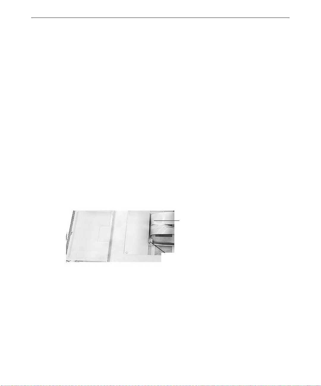
Floppy Disk Drive
To replace the floppy disk drive:
1. For ease of access, remove the chassis fan as described later in “Chassis Fan.”
2. Remove the CD-ROM drive as described previously in “CD-ROM Drive.”
3. Disconnect the power cable and data cable from the drive. Note the position of the red stripe
on the data cable.
Data
Cable
Power
Connector
4. Loosen the thumbscrew on the locking plate to the top left side of the peripheral device bay, as
described previously in “CD-ROM Drive.”
5. Lift and hold the locking plate.
6. From inside the chassis, push the back of the floppy disk drive until the bezel clears the front
of the chassis, and slide the device out.
Page 23
7. Remove the mounting guide on the left side of the floppy disk drive.
Mounting
Guide
Screws
Alignment Slot
8. Attach the mounting guide to the left side of the new floppy disk drive.
9. Raise the locking tab on the peripheral drive bay.
10. Slide the new floppy disk drive into the chassis and align the first slot on the mounting guide
with the locking plate tab.
11. Lower the locking plate, making sure the locking plate tab slides into the first slot on the
mounting guide.
12. Connect the data cable and power cable to the floppy disk drive.
13. Replace the CD-ROM drive as described previously in “CD-ROM Drive.”
14. Tighten the locking plate thumbscrew.
13
15. Replace the chassis fan, as described later in “Chassis Fan.”
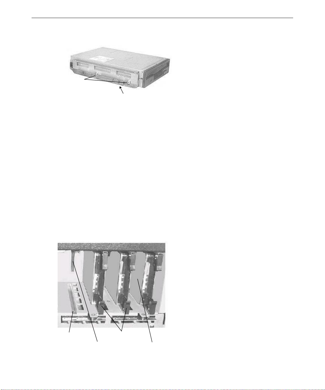
Removable Disk Drives
The disk drive bay may contain up to four removable Wide Ultra2 SCSI disk drives that provide
additional disk space for the system.
Drive Rail
Drive Connector
Latching Clips
Drive 0
Page 24

14
To replace a removable disk drive:
1. Open the disk drive bay door on the front of the system.
2. Flip the removable disk drive’s latching clips outward to disengage the drive. Wait 30
seconds to allow the drive to spin down and park the heads.
3. Carefully eject the drive completely from the rails, and remove it from the disk drive bay.
WARNING Handling a spinning disk drive or mishandling a removed disk drive can cause
the heads to crash! Subsequent failures may not be noticeable for three to six
months. Handle disk drives carefully to avoid damage.
4. Remove the drive mounting plate from the removed disk drive, making sure to retain the
mounting plate screws. Attach the mounting plate to the bottom (circuit board side) of the
new drive, using the four scr ews you retained from the removed drive.
WARNING Removing and attaching the drive mounting plate requires careful handling to
avoid contact with the delicate, electrostatic-sensitive parts on the circuit
board of the disk drive. Handle disk drives carefully to prevent failure and
voiding the warranty for the drives.
5. To insert the new removable disk drive, extend the latching clips on the drive and align the
rails on the sides of the drive with the slot guides in the disk drive bay. The metal casing of
the drive faces left.
6. With your thumb, push the mounting plate at the center between the latching clips until it
slides all the way into the slot and firmly engages the connector.
7. Close the latching clips to lock the drive in the slot.
8. Label the new drive with the same ADP, CH, and ID numbers used on the replaced drive, as
appropriate.
For more information on the removable disk drives, see Chapter 3, “Upgrading the System.”
Disk Drive Bay
The disk drive bay includes the disk drive cage, backplane, and LEDs. This assembly is always
replaced as one unit.
To replace the disk drive bay:
1. Remove all removable disk drives from the disk drive bay as described previously in
“Removable Disk Drives.” Note the original slot location for each drive. The drives should
be reinstalled in the same slot locations from which they we re removed.
Page 25
2. Remove and retain the six screws that attach the disk drive bay to the chassis. Support the
disk drive bay as the last screw is removed.
Disk Drive Section Screws
3. Gently pull forward on the disk drive bay until it is partially out of the chassis.
4. Note the location of the SCSI cable and disconnect it from the back of the disk drive bay.
15
Power
Connectors
SCSI Cable
5. Disconnect the power cables attached to the disk drive bay, using caution to avoid damage to
the cables and components on the disk drive backplane. Do not pull on the wires of the power
cables, as damage to the cables will occur.
6. Slide the disk drive bay the rest of the way out of the chassis.
7. Verify that the jump er settings on the back of the replacement disk drive bay match the one
being replaced.
NOTE If the system is configured to use the disk drive bay for RAID and to use the Mylex
RAID controller, the jumper connectors JP2 and JP3 must not have any jumpers
installed.
Page 26
16
8. If the old disk drive bay has a SAF-TE card (as described in the next section), remove it from
the old disk drive bay and install it in the same location on the new disk drive bay.
9. Insert the new disk drive bay partially into the chassis.
10. Reconnect the SCSI cable and power connectors in the same positions as the old disk drive
bay.
11. Insert the new disk drive bay the rest of the way into the chassis, and secure it with the screws
removed earlier.
12. Insert the removable disk drives into the disk drive bay as described previously in “Removable
Disk Drives.” The drives should be installed in the same slots from which they were remo ved.
13. Replace the front panel and cover.
14. Restart the system and ensure the LED for each drive lights.
SAF-TE Card
The SCSI Activity Fault-Tolerant Enclosure (SAF-TE) card is an option used on systems with
RAID configurations. I f your system has a RAID configuration with a SAF-TE card, use the
following procedure to replace the SAF-TE card.
To move or replace the SAF-TE card:
1. Remove the disk drive bay as described previously in “Disk Drive Bay.” The SAF-TE card is
located in the middle of the SCSI backplane on the back of the disk drive bay.
SAF-TE Card
Page 27
2. Press the two metal clips on the outside of the SAF-TE card mounting slot away from each
other, then gently rotate the SAF-TE card to a vertical position and remove it.
17
3. Place the SAF-TE card vertically in the mounting slot and rotate it toward the metal clips until
it snaps into place, with the clips securing the card. Use caution to avoid applying too much
force, as damage to the SAF-TE card and/or the disk drive backplane may result.
4. Replace the disk drive bay as described previously in “Disk Drive Bay.”
Power Supply
See Chapter 6, “System Hardware,” for technical information on the power supply.
To replace the power supply:
1. Unplug the AC power cord from the rear of the unit.
2. Remove the top cover. See Chapter 1, “Accessing the Components,” for details.
3. Note the location of all power cable connectors on the system board and peripheral devices:
Connector
P1 System board
P2 Reserved
P3 CD-ROM drive
P4 Floppy drive
P5 Reserved
P6 SCSI backplane (on disk drive bay)
P7 Reserved; use for peripheral drive bay device
P8 Reserved
P9 SCSI backplane (on disk drive bay)
Mounting Clips
Connects to
4. Disconnect all power cables from all internal devices and the system board.
Page 28
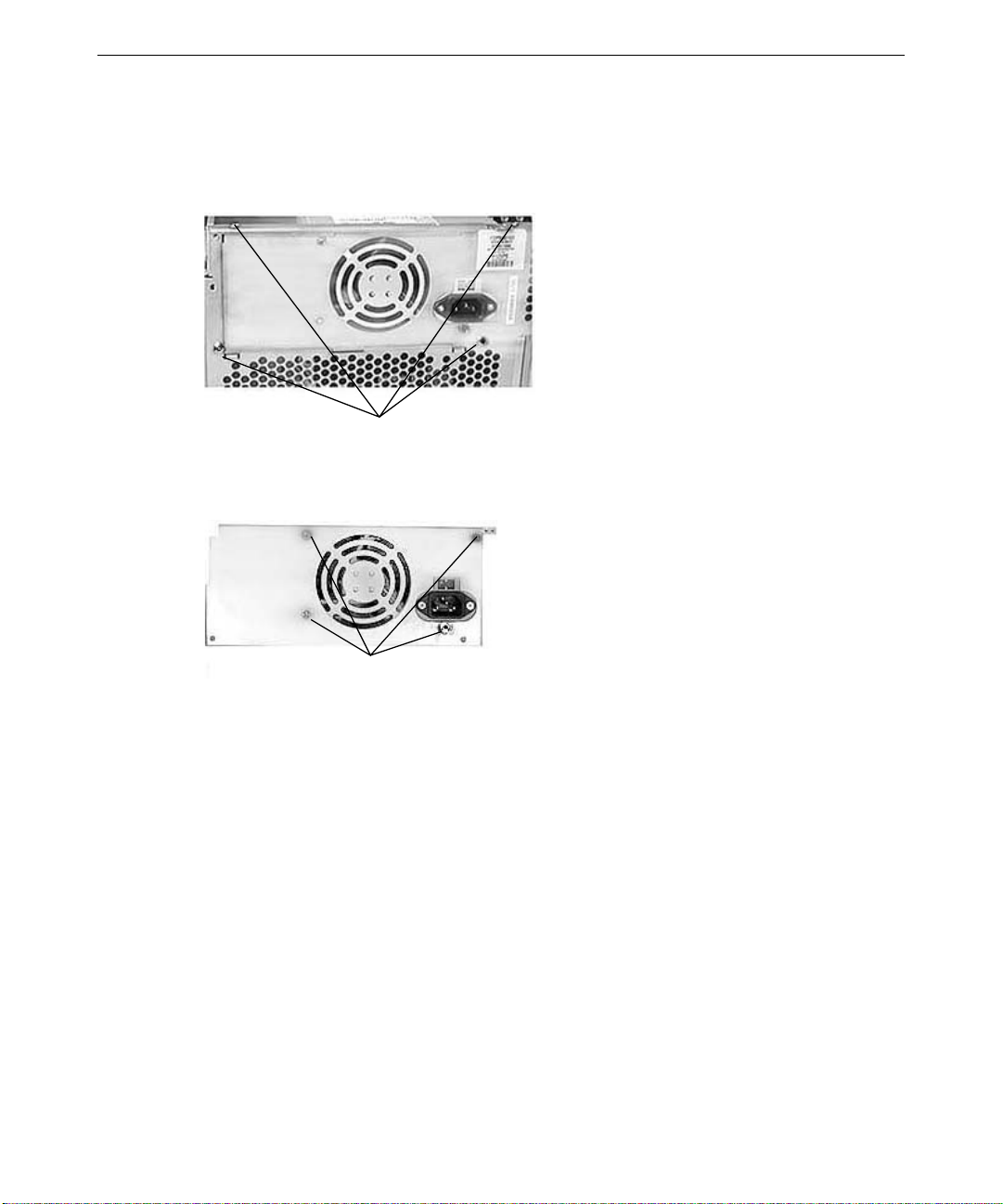
18
5. Remove and retain the fo ur screws securing the power supply and mounting plate to the back
and top of the system.
CAUTION Support the power supply as you remove the screws. Do not let the power supply fall
as you remove the fourth screw.
Power Supply Screws
6. Remove the old power supply and mounting plate.
7. Remove and retain the fo ur screws securing the mounting plate to the power supply.
Mounting Screws
8. Using the same four screws, attach the mounting plate to the new power supply.
9. Place the new power supply and mounting plate into the chassis, and secure it with the four
screws retained in step 3.
10. Make sure that the voltage selection switch on the back panel of the base unit is set to the
proper line voltage for your location. If your location uses 115 volts, make sure the number
115 is visible. If your location uses 230 volts, make sure the number 230 is visible.
WARNING If you do not set the voltage selection switch correctly, serious equipment
damage may result when you turn on power to the system.
11. Connect the power cables to the system board and internal devices. See Chapter 6, “System
Hardware,” for connection details.
Page 29
Processor Modules
For ease of access, you may have to remove the power supply as described previously in “Power
Supply.” See Chapter 4, “System Board,” for connector and socket locations.
To replace a passive processor module:
1. Remove the heat-sink lock from within the heat-sink fins, if necessary, by pressing the ends of
the lock inward and pulling lock outward.
2. Press the locking tabs on the top corners of the processor inward, towards each other, until
they click into the release position.
3. Slide the processor module out of the retention module.
4. Remove the new processor from its antistatic package, and align the processor module over
the retention module. The processor module is keyed and fits only one way.
19
Processor
Retention module
Heat sink mounting bracket
Heat sink lock
5. Press the processor module down until it seats.
6. Press the processor module locking tabs outward until they click into the locked position.
7. Install the heat-sink lock between the heat-sink fins, if necessary, by sliding the lock between
the fins and pressing it onto the heat-sink lock mounting posts.
The processor nearest the side of the chassis has a vertically oriented heat sink instead of a
horizontally oriented heat sink, as shown in the following figure. However, this processor
connects to the retention module in the same way as the other processor.
Page 30

20
Processor with
Vertically Oriented
Heat Sink
Procesor with
Horizontally Oriented
Heat Sink
To replace an active processor module:
1. Disconnect the processor’s cooling fan power cable from the processor fan power connector
on the system board.
2. Press the locking tabs on the top corners of the processor module inward, towards each other,
until they click into the release position.
3. Slide the processor module out of the retention module.
4. Remove the new processor from its antistatic package, and align the processor module over
the retention module. The processor module is keyed and fits only one way.
5. Press the processor module down until it seats.
6. Press the processor module locking tabs outward until they click into the locked position.
7. Connect the processor’s cooling fan power cable to the processor fan power connector on the
system board.
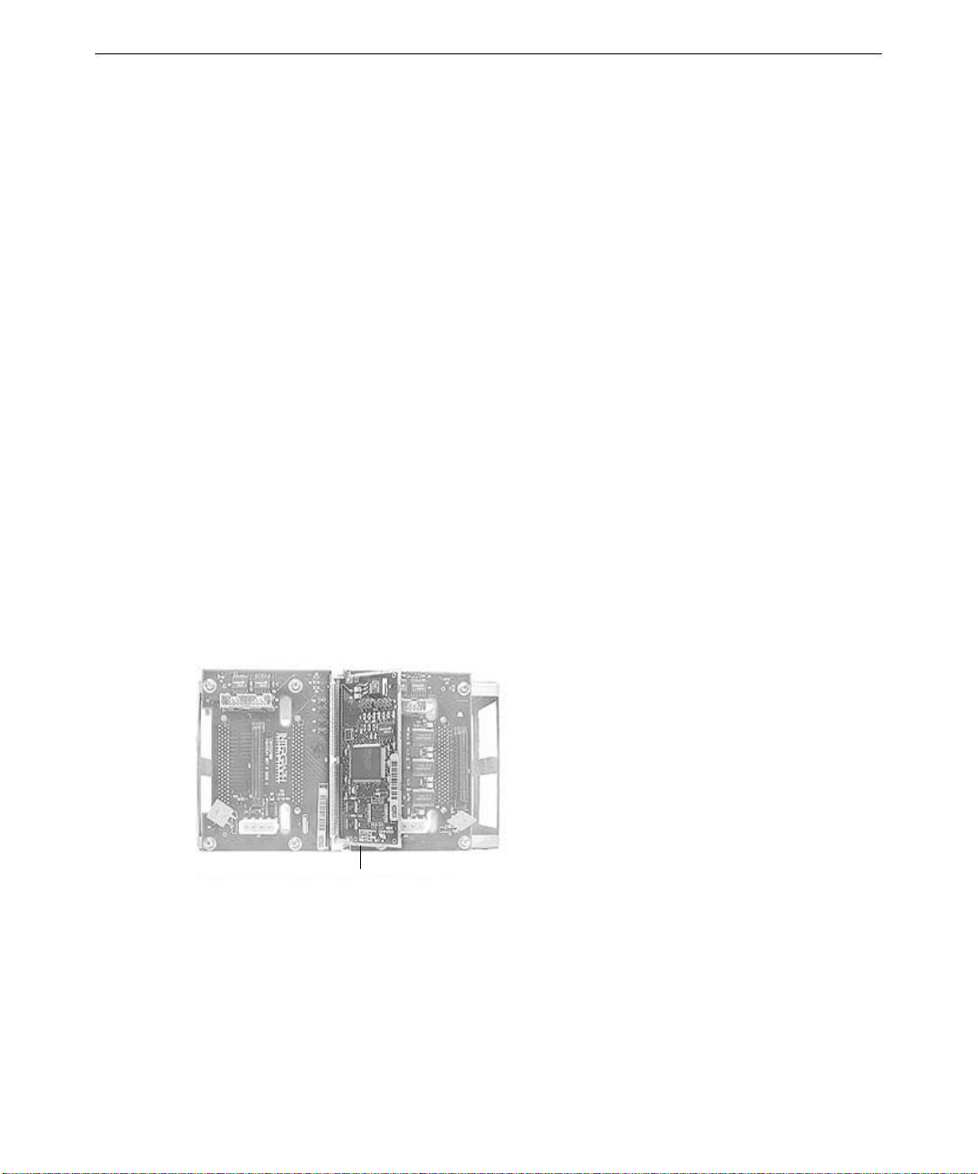
Heat-Sink Mounting Brackets
Pentium II and Pentium III processors equipped with heat-sink fins use heat-sink locks fastened to
mounting brackets to secure them to the system board. See Chapter 4, “System Bo ard,” for
connector and socket locations.
To replace a heat-sink mounting bracket:
1. Remove the processor module as described previously in “Processor Modules.”
2. Two mounting locks on the rear side of the system board secure the mounting bracket.
Remove these locks, and then remove the mounting bracket from the system board.
Page 31

3. The heat-sink mounting bracket has two pins on the bottom and four pins on the top. The
bottom two pins are of different sizes. The size of the pins and the holes in the system board
determine the correct orientation.
Insert the new heat-sink mounting bracket into the appropriate holes on the system board. The
bracket will click when it is correctly inserted. Ensure the four top pins are closest to the
processor slot.
4. Lock the heat-sink mounting bracket to the system board by inserting the two mounting locks
into the pins of the heat-sink mounting bracket, which are below the system board. The locks
will click when they are securely fastened.
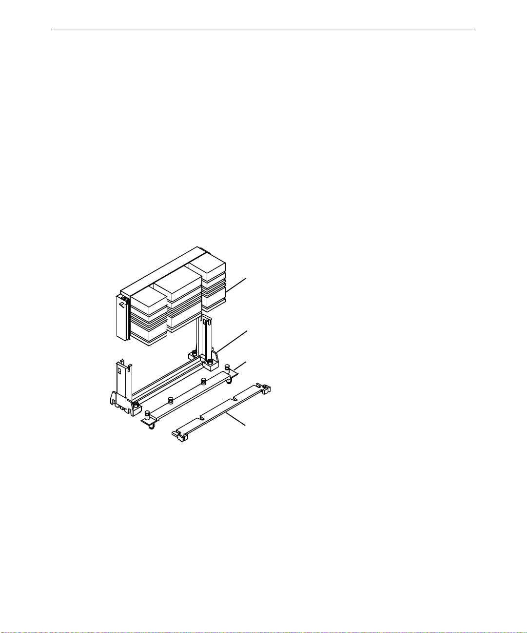
Retention Modules
Pentium II and Pentium III processors are secured to the system board using retention modules.
You do not need to replace a retention module to replace a processor module. See Chapter 4,
“System Board,” for connector and socket locations.
To replace a retention module:
1. Remove the processor module as described previously in “Processor Modules.”
2. Remove the heat-sink locks, if necessary, as described in “Heat-Sink Mounting Brackets.”
21
3. Remove the screws securing the retention module to the system board, and remove the
retention module.
4. Locate the key pin on one end of the processor slot on the board. Carefully line up the key
notch on the new retention module with the key pin on the processor slot. The key pin on the
processor slot indicates the correct orientation of the CPU.
5. Lower the retention module down over the processor slot so that the retention module seats
flatly against the system board. Tighten the screws in a clockwise manner to secure the
module to the board.
WARNING Do not overtighten the screws, as you may damage the module or the system
board.
6. Replace the heat-sink locks, if necessary, as described in “Heat-Sink Mounting Brackets.”
7. Replace the processor module as described in “Processor Modules.”
Page 32

22
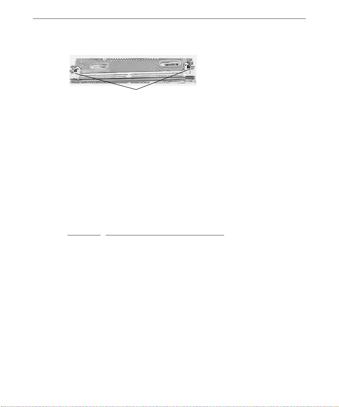
Dual Inline Memory Modules
CAUTION System memory modules from Intergraph Computer Systems are certified for use
with Intergraph computers at extremes of temperatures and system load to ensure
reliable performance. System memory modules available from other vendors may
not function properly or reliably in your Intergraph computer.
See Chapter 4, “System B o ard,” for DIMM socket locations.
To avoid damaging DIMMs and voiding the warranty, take the following precautions:
♦ Do not touch the gold -plated finger contact s.
♦ Do not bend, twist, drop, or otherwise handle DIMMs carelessly.
♦ Do not expose DIMMs to moisture or extreme temperatures.
♦ Do not remove DIMMs from the antistatic bag until installation.
Before you install DIMMs, do the following:
♦ Inspect DIMM keying. The slot keys on the DIMM must match the slot keys in the DIMM
socket. This ensures that you have the correct voltage and type of DIMM.
♦ Inspect DIMM contacts. The DIMM must have gold-plated fingers that match the gold-plated
socket contacts.
To replace a DIMM:
1. Press the release tabs outward, away from each other.
2. Grasp the top edge of the DIMM and pull it out of the socket.
3. Remove the new DIMM from the antistatic package.
4. Orient the DIMM so that the notches match the keys in the socket.
DIMM
Release Tab
Notch
DIMM socket
5. Push gently straight down until the release tabs snap into place.
6. Restart the computer for the BIOS to detect the new memory.
Page 33

System Board
You must swap the DIMMs and processor module(s) from the old system board to the new one if
you replace the system board. See Chapter 4, “System Board,” for connector and socket locations.
Note that a number of Fastex fasteners are mounted in the chassis (as shown in the following
figure) to secure the system board and provide support for the processor retention modules. Do
not overtighten the screws to these fasteners. If overtightened, the fasteners may distort.
To remove the system board:
1. Lay the chassis down on its right side.
2. Note the locations where all cables are connected to the system board.
3. Disconnect all cables from the system board.
23
Hole in chassis
Fastex fastener
4. Note the locations of the expansion cards, remove them, and place the cards on an antistatic
surface.
5. Remove DIMMs and processor module(s) and place them on an antistatic surface. See the
previous procedures in this chapter for details on removing these components.
6. Remove the jackscrews on all external port connectors.
WARNING Use care when removing or installing the screws to avoid damaging
components on the system board.
7. Remove the screws and the plastic rivets on the processor retention module(s), and remove the
retention module(s) from the chassis.
8. Remove the screws from the system board.
9. Lift the system board out of the chassis and place it on an antistatic surface.
To install a new system board:
1. Place the new system board into the chassis, align all mounting holes, and install the
jackscrews on the external port connectors.
2. Loosely install the remaining screws on the system board, except those for the processor
retention module(s). Do not tighten the screws yet.
Page 34

24
3. Mount the retention module(s) to the system board with the plastic rivets. The retention
module(s) is keyed to the processor slots to ensure correct orientation.
4. Tighten all fasteners that secure the system board and retention module(s) to the chassis.
5. Install the DIMMs and processor(s) to the system board.
6. Install the expansion cards back into their original slots.
7. Connect the internal cables to the system board. If you need help identifying cable
connections, see Chapter 4, “System Board.”
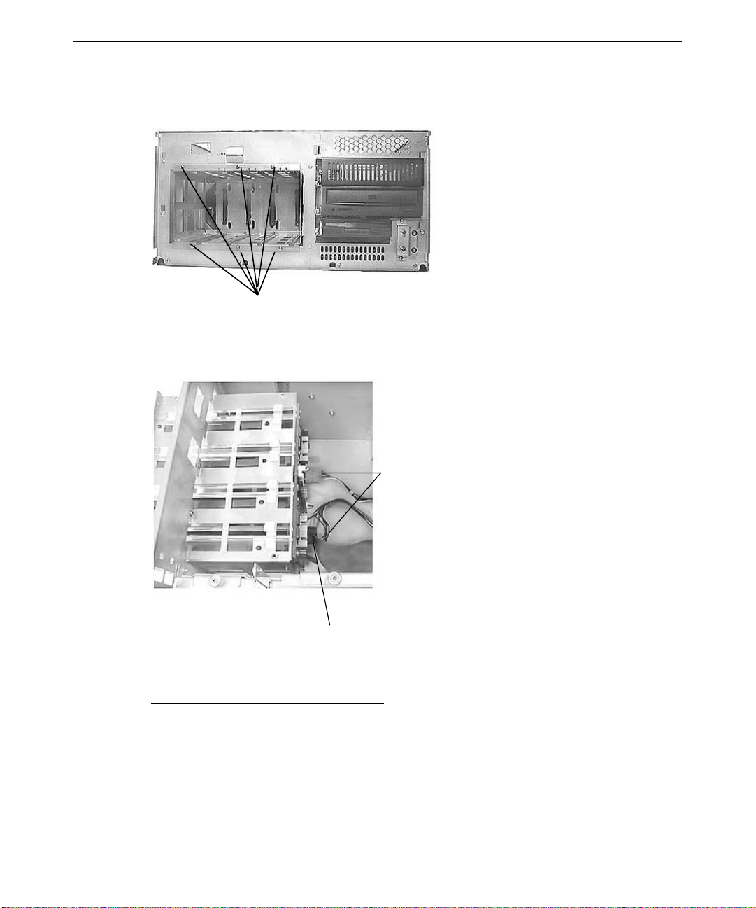
Expansion Cards
See Chapter 4, “System Board,” for connector and socket locations.
To replace an expansion card:
1. Disconnect cables attached to the expansion card connectors.
2. Disconnect any internal cable that connects the card to another device (if installed).
3. Remove the screw that secures the card to the left card guide.
4. Pull the expansion card straight out, and place it on an antistatic surface.
5. Slide the new card into the same slot from which you removed the old card.
6. Install the screw that secures the card to the left card guide.
7. Connect any cables from other internal devices, if installed.
8. Connect the external device to the expansion card connector on the rear of the system.
Chassis Fan
NOTE Arrows on the chassis fan indicate airflow direction and rotation. Ensure that you
See Chapter 6, “System Hardware,” for technical information on the chassis fan.
To replace the chassis fan:
1. Disconnect the fan power cable from the power supply connector.
install the new chassis fan with the airflow direction arrow pointing toward the back of
the chassis.
Page 35

25
2. Remove and retain the screw securing the mounting plate and fan to the chassis.
3. Loosen the thumbscrew attaching the mounting plate to the inside of the chassis.
Thumbscrew Mounting Screw
4. Note the airflow direction of the fan and the position of the fan on the mounting plate (the side
closest to the processors), and gently pull upward on the mounting plate until the mounting
plate and fan clear the chassis.
5. Remove and retain the four screws attaching the fan and fan grille to the mounting plate.
Fan Mounting
Screws
6. Ensure the airflow direction arrow on the new fan is pointing in the correct direction, then
attach the new fan and fan grille to the mounting plate using the same four screws.
7. Reinsert the mounting plate into the chassis, aligning the tabs on the bottom of the mounting
plate with the slots in the chassis.
8. Tighten the screws attaching the mounting plate and fan to the chassis.
9. Connect the fan power cable to the power supply connector.
Page 36

26
Disk Drive Bay Fans
See Chapter 6, “System Hardware,” for technical information on the disk drive bay fans.
To replace the disk drive bay fans:
1. Disconnect the fan power cable from the power supply connector.
2. Note the cable position and airflow direction of the old fan. Pull up on the metal tab attached
to the fan until it clears the chassis, carefully guiding the wires and connectors on the fan out
of the cable access hole at the bottom of the fan cage. Note the routing of the wires and
connectors on the old fan, as the new fan cables and connectors should be routed the same
way. See the following figure.
3. Route the power cable of the new fan through the cable access hole at the bottom of the fan
cage.
4. Insert the new fan into the fa n cage until it snaps into place.
5. Reconnect the fan power cable to the power supply connector.
Fan Tabs
CMOS/Clock Lithium Battery
The CMOS/clock lithium battery is located on the right side of the system board as seen from the
rear of the base unit. The battery may be hidden under installed expansion cards. See the
following figure.
After you remove the battery, the system will lose its operating parameters stored in CMOS
memory. As a result, the system BIOS parameters are lost. Parameters include date, time,
hardware configuration, and other data.
After you install the new battery, you must reset the date and time and reconfigure the BIOS. See
System Setup for details on updating and configuring the BIOS.
Page 37

Expansion Card Slots
CMOS/Clock Battery
WARNING There is a danger of explosion if the battery is incorrectly replaced.
WARNING Replace the battery with the same or equivalent type only, as recommended by
the battery manufacturer. Dispose of used batteries according to the battery
manufacturer’s instructions.
To replace the battery:
27
1. Remove any expansion cards that restrict access to the battery, as described previously in
“Expansion Cards.”
2. Note the positive orientation of the battery. Carefully remove the discharged battery by
grasping it firmly and pulling it out of the socket.
3. Install the new battery in the same orientation as the old battery.
4. Dispose of the battery according to the manufacturer’s instructions.
5. Install the expansion cards that you removed.
LEDs, Power, and Reset Switches
See Chapter 4, “System Board,” for connector and socket locations.
To replace the reset or power switches:
1. Open the face panel as described previously in “Base Unit Components.”
2. Disconnect the switch cable connector from the system board.
3. Remove the two screws attaching the LED and switch mounting plate to the chassis.
4. Disconnect the power and LED cables from the switch mounting plate. Note the position of
the cables before you disconnect them.
Page 38

28
5. Remove the switch button cover as shown in the following figure.
6. Insert the connector end of the switch cable through the cable access hole on the front of the
chassis and route the new switch cable through the chassis.
7. Connect the switch cable to the connector on the system board.
8. Press the switch into its mount on the switch plate and tighten.
9. Reconnect the power and LED cables to the appropriate LED or switch.
10. Replace the two screws attaching the mounting plate to the chassis.
11. Install the face panel and the power switch button.
Power/Reset
Switch Assembly
LED Assembly
To replace an LED:
1. Open the face panel. See Chapter 1, “Accessing the Components,” for details.
2. Note the locations of the two LEDs on the switch mounting plate.
3. Remove the switch mounting plate by removing the two screws attaching the plate to the
chassis.
4. Disconnect the power and LED cables from the switch mounting. Note the position of the
cables before you disconnect them.
5. Remove the LED from its mount on the switch plate as shown in the previous figure, then
disconnect the LED cable from its connector on the system board.
6. Remove the LED cable from the chassis.
7. Route the new LED cable through the chassis and connect it to the a ppropriate c onnector on
the system board.
Page 39

8. Press the LED into its mount on the switch plate.
9. Reconnect the power and LED cables to the appropriate LED or switch.
10. Reattach the switch plate to the chassis.
11. Close the face panel as described in Chapter 1, “Accessing the Components.”
29
Page 40

30
Page 41

3 Upgrading the System
This chapter describes how to upgrade your GT RAX system by adding or replacing system
components.
Before You Begin........................................................................................................................... 32
Adding Memory............................................................................................................................. 32
Upgrading Processors..................................................................................................................... 34
Adding Expansion Cards................................................................................................................ 34
Slot Locations................................................................................................................... 35
Installing Expansion Cards............................................................................................... 35
Expansion Cards with PCI-to-PCI Bridges ...................................................................... 36
Assigning System Resources............................................................................................ 36
Adding Removable Disk Drives..................................................................................................... 37
Adding an Internal SCSI Peripheral Device................................................................................... 37
Adding External SCSI Peripheral Devices..................................................................................... 40
SCSI Cable Lengths and Device Speeds .......................................................................... 40
SCSI Cable Quality.......................................................................................................... 41
SCSI IDs .......................................................................................................................... 41
SCSI Termination for External Devices........................................................................... 41
Connecting an External SCSI Drive................................................................................. 41
Changing SCSI Controller or Device Settings................................................................. 42
31
Page 42

32
Before You Begin
WARNING Disconnect the system and peripheral devices from AC power before servicing
internal components! Failure to remove AC power may result in equipment
damage or personal injury. The GT RAX system is always on when connected
to AC power.
WARNING Follow all warnings and cautions in the servicing instructions. If you fail to
follow documented procedures, personal injury and damage to equipment can
result.
CAUTION Use an antistatic wrist strap for all upgrading procedures to avoid the possibility of
electrostatic discharge.
CAUTION Do not overtighten screws and other fasteners to avoid damaging threads.
CAUTION Follow all warnings and cautions in these upgrade instructions. If you fail to follow
documented, approved procedures, personal injury or damage to equipment can
result.
See Chapter 1, “Accessing the Components,” for details on opening the system and protecting
against electrostatic discharge. These procedures assume you have removed the cover from the
system. “Right side” and “left side” are as seen from the front of the unit. After upgrading the
system, replace panels as described in Chapter 1, “Accessing the Components.”
Adding Memory
You can add system memory to the computer by adding or replacing dual inline memory modules
(DIMMs). The system board has six DIMM sockets, which combined can hold up to 3 GB of
Synchronous Dynamic Random-Acc ess Memory (SDRAM).
CAUTION System memory modules from Intergraph Computer Systems are certified for use
with Intergraph computers at extremes of temperatures and system load to ensure
reliable performance. System memory modules available from other vendors may
not function properly or reliably in your Intergraph computer.
Follow these population rules to correctly install the DIMMs:
♦ Install DIMMs one bank at a time.
♦ The system board has two memory controllers. The primary controller maintains DIMM
banks 0, 2, and 4. The secondary controller maintains DIMM banks 1, 3, and 5.
♦ If you are installing both unbuffered and registered DIMMs, you must install all of the
unbuffered DIMMs in the banks controlled by one memory controller, and all of the registered
DIMMs in the banks controlled by the other memory controller.
Page 43

♦ For best performance, populate both memory controllers equally when using an even number
of DIMMs. For example, if using two DIMMs, install them into Bank 0 and Bank 1.
See Chapter 2, “Servicing the System,” for instructions to install a DIMM. See Chapter 4,
“System Board,” for DIMM socket locations.
The following table shows possible memory configurations. Each bank contains one socket.
Primary Memory Controller Secondary Memory Controller
Memory
Bank 0 Bank 2 Bank 4 Bank 1 Bank 3 Bank 5
64 MB 64 MB
128 MB 64 MB 64 MB
128 MB
256 MB 64 MB 64 MB 64 MB 64 MB
128 MB 128 MB
256 MB
384 MB 64 MB 64 MB 64 MB 64 MB 64 MB 64 MB
128 MB 128 MB 128 MB
512 MB 128 MB 128 MB 128 MB 128 MB
256 MB 256 MB
512 MB
768 MB 128 MB 128 MB 128 MB 128 MB 128 MB 128 MB
256 MB 256 MB 256 MB
512 MB 256 MB
1 GB 256 MB 256 MB 256 MB 256 MB
512 MB 512 MB
1.5 GB 256 MB 256 MB 256 MB 256 MB 256 MB 256 MB
512 MB 512 MB 512 MB
2 GB 512 MB 512 MB 512 MB 512 MB
3 GB 512 MB 512 MB 512 MB 512 MB 512 MB 512 MB
33
Page 44

34
Upgrading Processors
When higher-speed processors become available, you can upgrade the existing processors to faster
processors.
Processors are mounted in a processor retention module that surrounds the processor slots. See
Chapter 2, “Servicing the System,” for information on replacing the processors. See Chapter 4,
“System Board,” for the location of processor slots and related connectors.
You can upgrade processors by purchasing a processor upgrade kit from Intergraph Computer
Systems. The kit contains the hardware, software, and documentation required for the upgrade.
After installing faster processors, you must reinstall Windows NT on the system to ensure proper
operation with the new processors.
Adding Expansion Cards
You can install Accelerated Graphics Port (AGP), Peripheral Component Interconnect (PCI), noncompliant PCI, Industry Standard Architecture (ISA), and Plug-n-Play (PnP) expansion cards in
the system. See below for a general description of the types of cards.
♦ PCI cards contain configuration registers that define reso urce information to the system during
startup. PCI cards do not require manual system configuration when installing the card. The
system BIOS detects the board’s presence during startup and reads information from the
board’s configuration registers to assign the necessary system resources.
NOTE All PCI expansion cards sold by Intergraph fully comply with the
Component Interconnect Specification, 2.1.
♦ Non-compliant PCI cards mechanically comply with the Peripheral Component Interconnect
Specification 2.1, but do no t contain configuration registers that allow the system to
automatically assign the necessary resources. These cards install in PCI slots, but you must
configure the BIOS to assign system resources before installing the card. In this regard, they
are like ISA cards, as described below.
♦ Non-PnP ISA cards do not contain registers that define the resource information to the system
during startup. Therefore, you must configure the BIOS to define the card to the system
before installing the ISA card. This reserves system resources for the card.
♦ PnP cards are ISA cards that contain configuration registers like PCI cards. During startup,
the system BIOS automatically detects the installed card and assigns the necessary system
resources. Since a PnP card is ISA-based, you install it in any available ISA slot.
NOTE Assign system resources for any non-PnP ISA card and any non-compliant PCI
cards before installation. See the “Assigning System Resources” section below.
Peripheral
Page 45

Each installed PCI card must draw less than 25 watts of power. The total allowable maximum
wattage fo r PCI cards is 175 watts. The PCI slots are limited to 25 watts power dissipation per the
Peripheral Component Interconnect Specification 2.1.
Slot Locations
See Chapter 4, “System B oard,” for the location of the expansion slots on the system board.
PCI slots 1 through 3 a re on a primary PCI bus connected to the primary LE chipset. PCI slots 4
through 7 are on a primary PCI bus connected to the secondary LE chip set. Slot 7 is a shared
PCI/ISA slot; you can install a PCI card or an ISA card in this slot, but not both.
35
Slot 0 - AGP
Slot 1 - PCI
Slot 2 - PCI
Slot 3 - PCI
Slot 4 - PCI
Slot 5 - PCI
Slot 6 - PCI
Slot 7 - PCI (shared)
Slot 7 - ISA (shared)
Installing Expansion Cards
If you are installing a double card set, such as a dual-card graphics controller, repeat the following
procedure for the second card. See the documentation that came with the card for details on
connecting the two cards.
For other cards, such as internal modems or SCSI controllers, see the documentation that came
with the card for details on installation, configuration, cable connections, and operation.
To install an expansion card:
1. Locate an open slot and remove the blanking plate for the slot. Keep the retaining screw.
NOTE If you have no open slots and/or want to replace an existing expansion card, see the
instructions in Chapter 2, “Servicing the System.”
Page 46

36
2. Remove the expansion card from its antistatic packaging.
3. Slide the expansion card carefully into the card guides. Ensure that the connectors on the
board’s edge are aligned properly with the slot connector.
4. Push the card into the slot firmly and evenly until it is fully seated in the slot connector.
5. Inspect the connection. If it does not appear to be correct, remove and reinstall the card.
6. Install the retaining screw.
7. Attach any required cables to the internal or external connectors.
Expansion Cards with PCI-to-PCI Bridges
If you add an expansion card with a PCI-to-PCI bridge to the system, you may encounter boot
problems. This happens because such a card essentially adds another PCI bus to the system, and
causes a renumbering of the PCI buses in the system. For example, if you add such a card to an
expansion slot on PCI bus 0:
♦ PCI bus 0 remains PCI bus 0
♦ The card becomes PCI bus 1
♦ PCI bus 1 becomes PCI bus 2
You must change the boot order in the SCSI Configuration Utility for the SCSI controllers on the
PCI buses to reflect the new PCI bus numbering. See System Setup for infor matio n on running and
using the SCSI Configuration Utility.
However, Windows NT will not use the boot order set by the SCSI Configuration Utility.
Windows NT always finds PCI bus 0 first. Ensure that your system’s primary boot device is on
PCI bus 0, and then use the SCSI Configuration Utility as needed to change boot order.
Assigning System Resources
Some expansion cards include a configuration diskette that you can use to reserve the system
resources required for the card. Other expansion cards do not include a diskette, but require that
you manually program the BIOS with the configuration information.
See System Setup for details on assigning system resources and configuring the BIOS for
expansion cards.
NOTE Treat non-compliant PCI cards and PCMCIA cards as ISA cards when assigning
system resources.
Page 47

Adding Removable Disk Drives
The system supports up to four 3.5-inch removable disk drives in the disk drive bay. Each
removable disk drive has a Single Connection Attach (SCA) connector for connection to the disk
drive bay backplane. The SCSI address of each removable disk drive is assigned by the disk drive
bay backplane.
JBOD (for “just a bunch of disks”) disk drives are controlled by an integrated dual-channel Low
Voltage Differential Signaling (LVDS) Wide Ultra2 SCSI controller. The disk drive bay (and thus
each removable disk drive) is connected to the Wide Ultra2 SCSI controller via Channel B.
A single-channel RAID (for “redundant array of independent disks”) controller and an optional
SCSI Activity Fault-Tolerant Enclosure (SAF-TE) card control RAID disk drives. The RAID
controller is connected to the backplane of the disk drive bay. The SAF-TE card is installed on the
disk drive bay backplane.
CAUTION Only use disk drives purchased from Intergraph in the disk drive bay. This ensures
the drives meet the disk drive bay specifications.
See Chapter 2, “Servicing the System,” or System Setup for information on installing removable
disk drives in the disk drive bay.
37
Adding an Internal SCSI Peripheral Device
A CD-ROM drive, a floppy disk drive, and the system disk drive are installed in the peripheral
device bay. You can add an optional SCSI peripheral device to the peripheral device bay unless
one is already installed there.
Except for the floppy disk drive, integrated SCSI controllers control the devices installed in the
peripheral device bay. The CD-ROM drive is connected to the Narrow Ultra SCSI controller; the
system disk drive is connected to the Wide Ultra2 SCSI controller via Channel A. The optional
SCSI device can be connected to either controller, as appropriate for the type of device installed.
The following table describes the devices in the peripheral device bay:
Drive
Floppy disk drive External 3.50-inch x 1.0-inch N/A
CD-ROM drive External 5.25-inch x 1.6-inch Narrow Ultra SCSI
System disk drive Internal 5.25-inch x 1.6-inch Wide Ultra2 SCSI Channel A
Peripheral device External 5.25-inch x 1.6-inch As appropriate for the device
Access Maximum Capacity SCSI Bus
Page 48

38
Remember the following when installing an optional SCSI peripheral device:
♦ The maximum speed of a SCSI bus is limited to the speed of the slowest device on that bus.
♦ Have the vendor’s documentation available to follow instructions for setting the SCSI ID,
enabling or disabling termination, installing device drivers when required, and configuring
other drive attributes.
♦ If you are installing a internal peripheral device that connects to an expansion card, see the
vendor’s documentation for installing the expansion card and required cables. See “Adding
Expansion Cards” for details.
♦ The length of the Wide Ultra2 SCSI cable is 30 inches (0.76 meters). The length of the
Narrow Ultra SCSI cable is 56 inches (1.4 meters).
See the following chapters for related information and important details:
♦ Chapter 6, “System Hardware,” for details on power supply cable connectors and pinouts.
♦ Chapter 7, “Peripherals,” for details on common internal devices and internal device cables.
To install a peripheral device in the available peripheral device bay:
1. Open the face panel as described in Chapter 1, “Accessing the Components.”
2. Loosen the thumbscrew on the locking plate near the top left corner of the peripheral device
bay.
Locking Plate
Thumbscrew
3. Lift the locking plate.
4. From inside the chassis, push the front of the tray and slide it out of the bay.
5. Set the SCSI ID on the new device to a n unused ID number.
6. Disable termination on the new device.
Page 49

7. Do one of the following:
− If installing a standard disk drive, place the disk drive in the tray, align the mounting
holes, and install the four mounting screws. See the following figure.
− If installing a 5.25-inch device, such as a tape drive or a CD writer, remove the right and
left mounting guides from the drive tray. Then attach the right mounting guide to the
right side of the device, and the left mounting guide to the left side of the device.
Drive
Mounting Guide
Drive Tray
39
Access Hole (2)
8. Do one of the following:
− Lift the locking plate, and install the tray assembly with standard disk drive into the
chassis, align the first slot on the mounting guide with the tab on the locking plate, and
lower the locking plate.
− Slide the 5.25-inch device into the chassis, align the tab on the locking plate with the first
slot on the mounting guide, and lower the locking plate.
9. Tighten the thumbscrew on the top of the locking plate to lock the device into place.
10. Connect the SCSI cable and the power cable to the device.
Page 50

40
Adding External SCSI Peripheral Devices
The system features integrated Narrow Ultra SCSI and Wide Ultra2 SCSI controllers. However,
only the Narrow Ultra SCSI controller has an external port. You can connect external singleended Narrow Ultra SCSI peripheral devices to this port. To connect external Wide Ultra or Wide
Ultra2 peripheral devices, you must install the appropriate SCSI controller as an expansion card.
NOTE Most SCSI controllers do not recognize a hard disk drive that was formatted using a
different brand of controller. For example, a hard disk drive formatted with an
Adaptec SCSI controller will not work with a Symbios SCSI controller. You must use
only Symbios-formatted hard disk drives with a Symbios SCSI controller.
SCSI Cable Lengths and Device Speeds
For each SCSI bus, the type of bus and the data clock speed of the fastest device on that bus
determine its maximum length. Knowing this, you can determine the maximum cable length you
can use to connect external SCSI devices to the system.
The following table provides a guide to maximum SCSI bus length. Note that bus width (for
example, Narrow versus Wi de) does not affect the maximum bus length.
Speed of the fastest
device on the bus
5 MHz (SCSI-1) 19.7 ft / 6 m 82 ft / 25 m 39.4 ft / 12 m
10 MHz (SCSI-2 or Fast) 9.8 ft / 3 m 82 ft / 25 m 39.4 ft / 12 m
20 MHz (Ultra or Fast20) 4.9 ft / 1.5 m 39.4 ft / 12 m 39.4 ft / 12 m
40 MHz (Ultra2 or Fast40) Not recommended Not specified 39.4 ft / 12 m
The total cable length on the system’s Narrow Ultra SCSI bus is the sum of the following:
♦ Narrow Ultra SCSI cable in the system−56 inches (1.4 meters)
♦ SCSI cable inside each internal device connected to the Narrow Ultra SCSI cable−typically 8
inches (0.2 meters) or less
♦ SCSI cable between the system and the first external device
♦ SCSI cable between each external device
Note that the maximum speed of a SCSI bus is limited to the speed of the slowest device on that
bus.
Single-ended bus Differential bus
Low-voltage
differential bus
Page 51

SCSI Cable Quality
To ensure data integrity and optimum performance, do the following:
♦ Use only Intergraph Computer Systems SCSI cables. Cables from other vendors may not
provide adequate shielding.
♦ Use the shortest cables possible to connect SCSI devices to the system and to each other.
CAUTION You should try to minimize cable flexing during handling. SCSI cables should not
have any creased bends. Take care when installing or replacing cables to insure that
they do not contact sharp metal surfaces or become excessively bent or twisted.
SCSI IDs
By default, specific devices use the following SCSI IDs:
♦ System disk drive (standard) uses ID 0
♦ SCSI controller always uses ID 7
♦ CD-ROM drive uses ID 4
♦ Zip, Jaz, or tape drive (optional) uses ID 6
41
NOTE To easily determine the ID of each SCSI device on the system, restart the system.
When the BIOS screen displays, look for the list of SCSI devices and write down the
ID for each device.
Some SCSI devices feature push switches to set the ID, while others have DIP switches or
jumpers. See the vendor documentation for details on setting the ID.
SCSI Termination for External Devices
Follow the guidelines below for terminating SCSI devices:
♦ Enable termination on the last external device on the SCSI cable chain.
♦ Disable termination on all other external devices on the SCSI cable chain.
♦ Use only an active terminator on externally terminated devices.
Connecting an External SCSI Drive
To connect an external SCSI drive:
1. Connect one end of the external SCSI cable to the Narrow Ultra SCSI port on the back of the
system.
2. Connect the other end of the cable to the SCSI device.
Page 52

42
3. Set the SCSI ID of the device to an unuse d number.
4. If the SCSI device is:
− The last or only device on the SCSI chain, enable SCSI termination
− Not the last or only device on the SCSI chain, disable SCSI termination
5. Ensure that the power switch on the device is in the off position, and then connect the power
cord to the device and then to an AC receptacle.
6. Turn on the power to the device and any other devices on the SCSI chain.
7. Start the system. If necessary, install the software drivers and configure the drive according to
the vendor’s instructions.
Changing SCSI Controller or Device Settings
You may need to use the SCSI Configuration Utility (PCI_CFG.EXE) to configure the operation of
SCSI peripherals connected to the integrated Symbios SCSI controllers. This utility enables you to
configure SCSI controllers, perform a low-level format on a SCSI hard disk drive, select boot
order, and verify media.
You may need to change SCSI controller parameters on a per-device basis under the following
conditions:
♦ If you are advised to do so by Intergraph Computer Systems technical support or instructed to
do so by the vendor documentation supplied with the SCSI device.
♦ If the SCSI device does not negotiate properly with the controller. This is common on older
drives.
♦ If you exceed the total cable length for connecting SCSI devices to the system, as specified in
the section, “Connecting an External SCSI Device,” in Chapter 1.
♦ If you connect non-Ultra or non-Wide Ultra2 SCSI external devices to the system.
For more information on using the SCSI Configuration Utility, see System Setup.
Page 53

4 System Board
This chapter provides cable and jumper connector information, major component descriptions,
memory subsystem details and addresses, and external port pinouts for GT RAX system board.
Slots and Sockets............................................................................................................................ 44
Connectors and Components.......................................................................................................... 45
Connectors...................................................................................................................................... 46
Jumper Functions............................................................................................................................ 49
Jumper Connectors......................................................................................................................... 50
CPU Frequency................................................................................................................ 50
Host Bus Frequency......................................................................................................... 51
External Ports................................................................................................................................. 52
Sound Processor............................................................................................................................. 58
43
Page 54

44
Slots and Sockets
The following diagram shows the location of slots and sockets on the system board.
DIMM
sockets
Primary processor slot
Secondary processor slot
0
2
4
1
3
5
AGP slot
PCI slots
PCI slot
(shared)
ISA slot
(shared)
0
1
2
3
4
5
6
7
8
Page 55

Connectors and Components
SCSI - J41
The following figur e shows cable connectors and other components on the system board.
J10 - Processor fan power - J48
COM2 - J11
J31
J32-J35
45
Power - J42, J43
Floppy disk
drive - J44
Speaker - J61
Power button - J55
MIDI/game - J14
CD in - J12
NOTE See Chapter 5, “System Hardware,” for information on power connectors J34 and
J38. See Chapter 6, “Peripherals,” for details on data cables.
J36
J16
J17
J18
J19
J20
J21
J22
J27
Battery
J24
J50, J56
Chassis
fan power
Narrow Ultra
SCSI termination
(L) Channel A - J38
(R) Channel B - J39
Green LED - J51
Yellow LED - J57
HDD LED - J58
Wide Ultra2 SCSI
Channel A - J63
Channel B - J64
Page 56

46
Connectors
Connector Cable Description
J10 Not included Primary processor fan power
J11 MCBLW68 Serial port 2 (COM2)
J14 MCBL038 MIDI/game connector
J41 MCBL387 Narrow Ultra SCSI
J42 P1 System board power
J43 P2 System board power
J44 MCBL194 Floppy drive CDSK146
J48 Not included Secondary processor fan power
J51 MCBL248 Front panel power LED (green)
J50 Not included Chassis fan
J55 MCBL250 Front panel power button
J56 CFAN120 Chassis fan, bottom front
J57 MCBL249 Front panel power management LED (yellow)
J58 MCBL247 Front panel disk activity LED (green)
J61 MCBL520 Speaker
J63 MCBL339 LVDS Wide Ultra2 SCSI Channel A
J64 MCBL340 LVDS Wide Ultra2 SCSI Channel B
J10 - Power Supply Fan Cable, 2-Wire
Pin
1 Voltage +
2 Return -
J10 - Power Supply Fan Cable, 4-Wire
Pin
1 Fan control input 3 Voltage +
2 Fan Tach 1 4 Return -
J11 - MCBLW680A, Serial Port 2
See “External Ports” in this chapter for serial port pinouts.
Signal
Signal Pin Signal
Page 57

J12 - MCBL199A1, CD-ROM Audio
47
Pin
Signal Pin Signal
1 Right Sound Channel 3 Left Sound Channel
2 Ground 4 Ground
J41 - MCBL387, Internal Narrow Ultra SCSI
Pin
Signal Pin Signal Pin Signal Pin Signal
2 SD-(0) 16 SD-(7) 30 Ground 44 SSEL4 SD-(1) 18 SDP0- 32 SATII- 46 SCD6 SD-(2) 20 Ground 34 Ground 48 SREQ8 SD-(3) 22 Ground 36 SBSY- 50 SIO10 SD-(4) 24 Reserved 38 SACK12 SD-(5) 26 TPWR 40 SRST14 SD-(6) 28 Reserved 42 SMSG-
Remaining pins are connected to ground.
J44 - MCBL194, Floppy Disk Drive
Pin
Signal Pin Signal Pin Signal
2 RPM 14 DRV0- 26 T RK04 No connect 16 M TR1- 28 WRPRT6 DRATE0 18 DIR 30 RDATA8 INDEX- 20 ST EP- 32 HDSEL
10MTR0- 22WDATA-34DSKCHG
12 DRV1- 24 WGATE-
J51 - MCBL248, Power On LED (green)
Pin
Signal
1 PwrGood
2 Ground
J55 - MCBL250, Front Panel Power Switch
Pin
Signal
1 + 5 V trickle
2 PWRBTN
Page 58

48
J56 - CFAN120, Chassis Fan (bottom front)
Pin
Signal Pin Signal
1 Fan control input 3 Voltage +
2 Fan Tach 4 Return -
J57 - MCBL249, Power Management LED (yellow)
Pin
Signal
1 PwrGood
2 Ground
J58 - MCBL247, Disk Activity LED (green)
Pin
Signal
1 DiskActive
2 Ground
J61 - MCBL250, Speaker
Pin
Signal
1Audio
2 Ground
J63 - MCBL339, Internal Wide Ultra2 SCSI
J64 - MCBL340, Internal Wide Ultra2 SCSI
Pin
Signal Pin Signal Pin Signal
17TERMPWR45SD-(5) 57SBSY18TERMPWR46SD-(6) 58SACK35 SD-(12) 47 SD-(7) 59 SRSI36 SD-(13) 48 SDP0- 60 SMSG37 SD-(14) 49 Ground 61 SSEL38 SD-(15) 50 Ground 62 SCD39 SDP1- 51 TERMPWR 63 SREQ40 SD-(0) 52 TERMPWR 64 SIO41 SD-(1) 53 No connection 65 SD-(8)
42 SD-(2) 54 Ground 66 SD-(9)
Page 59

Pin Signal Pin Signal Pin Signal
43 SD-(3) 55 SATII- 67 SD-(10)
44 SD-(4) 56 Ground 68 SD-(11)
Remaining pins are connected to ground.
Jumper Functions
Jumper Description
W4 BIOS is flashable when jumpered
W5-W7 Routes outer USB port to AGP port when pins 2-3 are jumpered
W11 Enables on-board audio if jumpered
W12 When closed, sets processor speed in BIOS
J16-J22 PCI expansion slots
J22 PCI expansion slot (shared)
J24 ISA expansion slot (shared)
J27 AGP expansion slot
J31-J36 DIMM memory module sockets
J38 Channel A Wide Ultra2 SCSI termination
J39 Channel B W ide Ultra2 SCSI termination
J53 Clears CMOS when pins 2-3 are jumpered
J52, J59, J60, J62 Processor frequency
J15, J29, J30 Host bus frequency
49
Page 60

50
Jumper Connectors
CPU Frequency
The following table shows the jumper settings for CPU frequency. ON denotes the jumper is
installed on both pins.
Jumper
J52 ON OFF
J59 OFF OFF
J60 OFF ON
J62 ON ON
450 MHz 500 MHz
DIMM sockets
Ultra SCSI - J41
CPU frequency J52, J59, J60, J62
Page 61

Host Bus Frequency
The following table shows the jumper settings for host bus frequency. ON denotes the jumper is
installed on both pins.
51
Jumper
66 MHz 100 MHz
J15 ON OFF
J29 ON OFF
J30 ON OFF
AGP slot
J30
PCI slots
Secondary processor
J29J15
DIMM
sockets
Page 62

52
External Ports
The following figur e shows the external ports on the back of the unit.
Narrow Ultra SCSI
Mouse
Keyboard
COM 1 (Serial)
LPT1 (Parallel)
Keyboard, Mouse
The keyboard and mouse ports are PS/2 style, 6-pin ports. The two ports are not
interchangeable.
2 4 6
1 3 5
COM 2 (Seria l)
Ethernet
Universal Serial Bus
Pin
Signal
1 KDATA (keyboard)
MDATA ( mouse)
2Spare
3 Ground
4VCC
5KCLK
6Spare
MIDI/Game
Microphone
Line out
Line in
Page 63

Serial
1
2
The serial ports (also referred to as RS-232 asynchronous communications ports,
or COM ports) connect modems, printers, peripherals, and other computers to the system. The
serial ports (labeled 1 and 2) are 9-pin, male DB9 connectors. If connecting a serial device with a
25-pin DB25 connector, use a 25-pin to 9-pin adapter cable to mate with the serial port on the
system. Use only shielded cables with the serial ports.
53
6
1
Pin
1 DCD - Data Carrier Detect
Signal
2 RD - Receive Data
9
5
3 TD - Transmit Data
4 DTR - Data Terminal Ready
5 Ground
6 DSR - Data Set Ready
7 RT S - Request to Send
8 CTS - Clear to Send
9 RI - Ring Indicator
Parallel
The parallel (LPT) port is used almost exclusively to connect a printer to the system.
However, it is compatible with any peripheral device designed to interface with a Centronics-type
parallel port. Use only shielded cables with the parallel port (DB-25).
14
1
Pin
Signal Pin Signal
1 -Strobe 10 -ACK - Acknowledge
2 Data 0 11 Busy
3 Data 1 12 PE - Paper Empty
4 Data 2 13 +Select
5 Data 3 14 -Auto FDXT - Auto Feed
6 Data 4 15 -Error
25
13
7 Data 5 16 -Init - Start
8 Data 6 17 -SLCTIN - Select
9 Data 7 18-25 Ground
Page 64

54
Line Out
The Line Out port connects a set of speakers to the system. You can also use the port to
connect other audio output devices, such headphones, a tape deck, or an external amplifier, to the
system.
Pin
2
5
Signal
1 Ground
2 Left Channel Out
5 Right Channe l Out
1
Line In
The Line In port connects audio input devices, such as a tape deck or a CD player, to the
system.
Pin
2
5
Signal
1 Ground
2 Left Channel In
5 Right Channe l In
1
Page 65

Microphone
The Microphone port connects a microphone to the system. You can also use the port to
connect a headset microphone to the system.
55
2
5
Pin
Signal
1 Ground
2MIC 2
5MIC 1
1
Game/MIDI
The Game/MIDI port connects a game joystick or a MIDI device, such as a musical keyboard
or synthesizer, to the system.
15
1
Pin
Signal Pin Signal
1 +5V 9 +5V
2 Fire button 0 10 Fire button 2
3 X-axis, joystick 1 11 X-axis, joystick 2
4 Ground 12 MIDI out
5 Ground 13 Y-axis, joystick 2
6 Y-axis, joystick 1 14 Fire button 3
9
8
7 Fire button 1 15 MIDI in
8+5V
Page 66

56
Ethernet
The Ethernet port connects a network cable (with an RJ45 connector) to the system.
1
Pin
Signal Pin Signal
1 T D+ - Transmit 5 Reserved
2 T D– - T r ansmit 6 RD– - Receive
3 RD+ - Receive 7 Reserved
4 Reserved 8 Reserved
8
Universal Serial Bus
The Universal Serial Bus (USB) port connects USB devices to the system. These devices
can include printers, keyboards and other peripherals that have historically used serial, parallel,
mouse, and keyboard I/O buses. USB devices, designed to be fully Plug-and-Play (PnP), feature
hot attach/detach and daisy-chain capabilities. The USB port can transfer data at a maximum
theoretical rate of 12 megabits per second.
1
Pin
4
Signal Pin Signal
A1 PWR B1 PWR
B
A2 - B2 A3 + B3 +
A4 GROUND B4 GROUND
A
1 4
Page 67

Narrow Ultra SCSI
The Narrow Ultra SCSI port connects external SCSI devices, such as tape drives or hard
disks, to the system’s Narrow Ultra SCSI bus. The maximum sustainable data transfer rate is 40
MB per second.
NOTE Pins 12, 13, 14, 37, and 39 are not connected; pins not listed are connected to
ground.
Pin Signal
26 Command Data-0
50
25
27 Command Data-1
28 Command Data-2
29 Command Data-3
30 Command Data-4
31 Command Data-5
32 Command Data-6
33 Command Data-7
34 Command Data Parity
38 Terminator Power
26
1
41 Attention
43 Busy
44 Acknowledge
45 Reset
46 Message
47 Select
48 Command
49 Request
50 Input/Output
57
Page 68

58
Sound Processor
The system’s on-board sound processor is the Ensoniq ES1371 AudioPCI processor. The ES1371
offers support for 64 voices, and is DirectX 5.0 and ACPI compliant. The on-board ES1371 may
be software disabled if an add-in audio processor is preferred. Line-in, line-out, and Mic-in jacks
are provided on the rear of the motherboard/chassis. Integrated onto the system board, the
processor is a complete, fully featured PC 97 compliant sound implementation. It has the
following specifications:
Feature
Audio Resolution 16-bit
MIDI/UART Mode Compatibility Roland MPU401
Bus Interface 16-bit PCI
CODEC Delta Sigma-based Windows Sound System
CODEC FIFO 16 Samples
FM Synthesizer Crystal internal FM synthesis
External Audio Inputs Microphone (Monaural), Stereo Line-In
Internal Audio Inputs Stereo FM Synthesis, Stereo Wave Data, Stereo CD,
Audio Outputs Stereo Line-Out
MIDI/Joystick MIDI In, MIDI Out, up to 4 fire buttons
ADPCM Audio Compression 4:1, 3:1, and 2:1
Sampling Rate Range 5 KHz - 44.1 KHz in 228 selectable steps
The Ensoniq ES1371 AudioPCI sound processor is configured entirely through I/O port accesses.
When the system is powered up, the hardware forces the Ensoniq ES1371 to respond to default I/O
port addresses, interrupt request (IRQ) level, and direct memory access (DMA) request and
acknowledge. The following table shows the default sound processor configurations and available
programmable settings.
Parameter
Base I/O Address / MPU-401 220/330
8-bit Playback DMA 1
8-bit Capture DMA 3
Base IRQ / MPU IRQ 5/15
Specification
Monaural PC Speaker
Default
Page 69

5 System Resources
This chapter provides information on system resources such as interrupt requests (IRQs), direct
memory access (DMA) channels, input/output (I/O) addresses, and memory addresses.
See System Setup for information on running the BIOS Setup program and changing BIOS
parameter settings.
Available IRQs............................................................................................................................... 60
Freeing IRQs .................................................................................................................................. 60
PCI Devices.................................................................................................................................... 60
PCI to ISA Bus Interrupt Mapping................................................................................................. 60
Configuration Data......................................................................................................................... 61
Interrupt Requests (IRQs)................................................................................................ 61
DMA Channels................................................................................................................. 62
Input/Output Addresses.................................................................................................... 62
Memory Address Map...................................................................................................... 63
59
Page 70

60
A v ailable IRQs
IRQs 5 and 10 are available for assignment. If a non-Plug And Play compliant ISA card is
installed, set it to use either IRQ 5 or IRQ 10. In BIOS Setup, the selected IRQ must be set to
reserved.
Freeing IRQs
To free IRQs for use by an ISA device or a PCI device that uses drivers that do not comply with
the PCI 2.l specification, you can use the system BIOS to disable unuse d system ports.
To disable an unused system port:
1. Restart the system and press
2. Select Setup, and then select Peripheral Setup.
3. Select the port you want to disable (OnBoard Serial Port 1, OnBoard Serial Port 2, or
OnBoard Parallel Port).
4. Change the value of the setting to Disabled.
5. Save the changes and exit from BI OS Setup.
DEL when prompted to enter Setup.
PCI Devices
The system’s PCI expansion slots comply with the PCI 2.1 specification. Devices that comply
with the PCI 2.1 specification are fully plug-and-play. You do not have to configure them after
installation.
Some older PCI device drivers cannot share an interrupt, which is a violation of the PCI 2.1
specification. If you install a device that uses such a driver, you must free an IRQ for the device to
work in the system.
PCI to ISA Bus Interrupt Mapping
The system’s ISA bridge provides the sixteen conventional ISA interrupts, plus four interrupt
request pins for PCI peripheral interrupts (PIRQ0 through PIRQ3). For PC-AT architecture
compatibility reasons, the PCI interrupts are routed to the ISA interrupts within the ISA bridge.
The assertion of a PCI interrupt concludes in an ISA interrupt being asserted.
Bit 7 of each PIRQ registers enable (Low) or disable (High) the routing of the PIRQ to an ISA
interrupt. The lowest four bits (3:0) of each PIRQ register determines to which ISA interrupt the
PIRQ is routed.
Page 71

You can map the PIRQs to the following ISA interrupts:
IRQs 5, 10, 11, 15
You can also map to IRQs 3, 4, 7, 12, and 14, but other devices are disabled if you do so.
Each PCI slot has four available interrupt lines: INTA, INTB, INTC, and INTD. These are
connected to the PCI interrupts, P IRQ0 through PIRQ3, as shown below:
61
Interrupt Line
INTA PIRQ0 PIRQ1 PIRQ2 PIRQ3 PIRQ0 P IRQ1 PIRQ2
INTB PIRQ1 PIRQ2 PIRQ3 PIRQ0 PIRQ1 PIRQ2 PIRQ3
INTC PIRQ2 PIRQ3 PIRQ0 PIRQ1 PIRQ2 PIRQ3 PIRQ0
INTD PIRQ3 PIRQ0 PIRQ1 PIRQ2 PIRQ3 P IRQ0 PIRQ1
Slot 1 Slot 2 Slot 3 Slot 4 Slot 5 Slot 6 Slot 7
Configuration Data
Interrupt Requests (IRQs)
System interrupt request (IRQ) assignments are defined below.
IRQ
0 System Timer 8 Real Time Cloc k
1Keyboard 9SMBUS/ACPI
2 Cascade input for IRQ8 - IRQ15 1 0 Ensoniq ES1371 AudioPCI Processor
3 COM2, COM4 11 Hardware Monitor
4 COM1, COM3 12 Mouse
5 MIDI p ort 13 Floating Point Unit
6 Floppy Controller 14 Spare
7 Parallel Port 15 Spare
Name IRQ Name
You can assign the spare interrupt listed above to an ISA device. When you add a PCI device to
the system, the system BIOS automatically assigns the interrupt. However, at least one interrupt
must be available for the PCI bus.
When you add an ISA board, you must reserve the interrupt using the BIOS Setup utility and
jumpers on the expansion board. See the vendor documentation for the expansion board for
jumper and related information.
Page 72

62
DMA Channels
The system board uses Direct Memory Address (DMA) channels to exchange data without
accessing the CPU. Some channels are assigned for specific use by the system, as defined below.
Each DMA channel appropriates full 32 -bit processing. For an ISA bus, channels 0 through 3 are
8-bit and channels 4 through 7 are 16-bit cha nnels.
DMA
0 LPT1 (if in ECP mode) 4 Cascade input for 0-3
1Spare 5Spare
2 Floppy Controller 6 Spare
3Spare 7Spare
Assignment DMA Assignment
Input/Output Addresses
The following table lists a small subset of the reserved I/O addresses.
Address
0278 - 027F Parallel Port LPT2
02E8 - 02EF Serial Port COM4
02F8 - 02FF Serial Port COM2
0378 - 037F Parallel Port LPT1
03B0 - 03BF Monochrome Display/Printer Adapter
03C0 - 03CF Enhanced Graphics Adapter (EGA/VGA)
03D0 - 03DF Color/Graphics Monitor Adapter (CGA/MCGA)
03F0 - 03F7 Floppy Controller
03F8 - 03FF Serial Port COM1
Device
Page 73

Memory A ddress Map
The following table lists the memory address map assignments.
63
Memory Address
00000000 - 0009FFFF 640K System board memory
000A0000 - 000BFFFF 128K Video memory
000C0000 - 000C7FFF 32K Video ROM
000C8000 - 000DFFFF 96K Available I/O Adapter ROM
000E0000 - 000EFFFF 64K BIOS ROM and PCMCIA
000F0000 - 000FFFFF 64K BIOS ROM
00100000 - 1FFFFFFF 511M Expansion memory
20000000 - 3FFFFFFF — Reserved
Size Assignment
Page 74

64
Page 75

6 System Hardware
This chapter contains technical information about GT RAX hardware.
Hardware Overview........................................................................................................................ 66
Functional Diagram........................................................................................................................ 67
System Board Block Diagram........................................................................................................ 68
SCSI Cable Routing........................................................................................................................69
Disk Drive Bay............................................................................................................................... 70
Cable Routing and Pinouts............................................................................................... 70
Jumper Settings................................................................................................................ 72
Removable Disk Drive LEDs........................................................................................... 72
Power Supply..................................................................................................................................73
Chassis Cooling Fans...................................................................................................................... 74
Disk Drive Bay Cooling Fans ......................................................................................................... 75
Hardware Monitoring and Power Management.............................................................................. 75
65
Page 76

66
Hardware Overview
If your system includes any of the following hardware, refer to the documentation delivered with
the hardware for additional information:
♦ Monitor, keyboard, and concentrator
♦ Zip, Jaz, or tape drive
♦ Dual-channel LVDS Wide Ultra2 SCSI controller (integrated on system board)
♦ Single-channel Narrow Ultra SCSI controller (integrated on system board)
♦ Single-channel RAID controller (expansion card)
♦ Fibre Channel host bus adapter (expansion card)
♦ AC power distribution box
♦ Uninterruptible power supply
The following figure shows the major parts and assemblies inside the system.
Peripheral
Device Bay
Face Panel
Power Supply
Input/Output Panel
Chassis Fan/
Mounting
Plate
Disk Drive Bay
Disk Drive Bay
Fans
Expansion Slots
Page 77

Functional Diagram
The following diagram shows the power and data signals of the base unit components.
67
Power
Data
Power and Data
System Board
Speaker
Keyboard
Mouse
Graphics
Adapter
Serial
Ports
AC In
Power Supply
Fan
Floppy Disk Drive
CD-ROM Drive
Parallel
Port
USB
Ports
SCSI
Controller
Disk Drives
(Internal/External)
Page 78

68
System Board Block Diagram
The following diagram shows how the system board components are linked.
DIMMs
0
2
4
AGP
Ethernet
Audio
BIOS
HW Mon
Slot 1 CPU
Primary LE
1
2
3
South
Bridge
PCI Bus
I/O
Controller
PCI slots
4
5
6
Wide Ultra2 SCSI
Slot 1 CPU
Secondary LE
7
Narrow Ultra SCSI
PCI BusPCI BusISA Bus
DIMMs
PCI slot
ISA slot
ISA Bus
1
3
5
Page 79

SCSI Cable Routing
The following diagram shows how the SCSI cables should be routed when connecting SCSI
devices in the system.
CAUTION You should try to minimize cable flexing during handling. SCSI cables should not
have any creased bends. Take care when installing or replacing cables to insure that
they do not contact sharp metal surfaces or become excessively bent or twisted.
69
Peripheral Bay
In the peripheral bay:
Disk Drive Bay
Wide Ultra2 SCSI
Channel B
Wide Ultra2 SCSI
Channel A
System Board
Narrow Ultra
SCSI
External Narrow
Ultra SCSI Port
Chassis
Narrow Ultra SCSI
Wide Ultra2 SCSI Channel A
Wide Ultra2 SCSI Channel B
♦ The Narrow Ultra SCSI cable connects to the CD-ROM drive. It can also connect to another
installed Narrow Ultra SCSI device. The cable is 56 inches (1.4 meters) long.
♦ The Wide Ultra2 SCSI Channel A cable connects to the system disk drive. It can also connect
to another installed LVDS Wide Ultra2 SCSI device. The cable is 30 inches (0.76 meters)
long.
Page 80

70
J20
Disk Drive Bay
The disk drive bay includes the disk drive cage and a Small Computer Systems Interface (SCSI)
backplane. This assembly is always replaced as one unit.
The SCSI backplane is a Low Voltage Differential Signal (LVDS) SCSI compliant backplane. It
is designed to connect up to four SCSI devices to a system in which the backplane is installed.
These SCSI devices must use the Single Connection Attach (SCA)-2 connectors that incorporate
connections for power and status lines, as well as the signals comprising the wide SCSI bus.
Cable Routing and Pinouts
The following picture shows the jumpers on the SCSI backplane.
J7
J21
J15
J1
J9
J8
J17
J2
J5, J6,
J10, J11
J18
J3
J19
J16
J4
J14
U7, U8, U9
SCSI drive connection is made through connectors J1 – 4. These are the only connectors on the
front of the backplane. Connection for an optional SCSI Accessible Fault-Tolerant Enclosure
(SAF-TE) card is through J18 , which is a 72-pin SIMM connector.
CAUTION J18 is designed to connect only to a SAF-TE card. Do not connect a single inline
memory module (SIMM) to this location.
J15 and J14 are the 68-pin SCSI connectors for connecting the backplane to an LVDS SCSI
controller. J15 is the input connector. J14 is only used to daisy-chain multiple disk drive bay
backplanes.
Page 81

J16 and J17 provide power (+12V, +5V, Ground) to the backplane. Both connectors must be used
for proper operation.
J20 and J21 are auxiliary bus connectors used in multiple backplane configurations only. J9 is
used only in multiple backplane configurations and should not be installed.
U7-9 are the LVD SCSI termination circuits. These provide the bus termination necessary for
proper operation.
Disk Drive Bay Backplane Connections
71
From the Backplane
To
J1, J2,.J3, J4 SCSI drive connectors
J5, J6, J7, J8, J9, J10, J11 Reserved
J14, J15 LVDS SCSI controller
J16, J17 Power supply cables P6 and P9 (+12V, +5V, Ground)
J18 Optional SAF-TE card
J20, J21 Auxiliary bus
U7-9 LVDS SCSI termination
J16, J17 - Power Connector Pinout
Pin
Signal Wire Color Pin Signal Wire Color
1 +12V Yellow 3 Ground Black
2 Ground Black 4 VCC, +5v Red
CH0 and CH1 - Disk Data Cable Pinout
Pin
Signal Pin Signal Pin Signal
1-16 Ground 43 SCSI Data Bit 3 56 Fault Data
17 Term Power 44 SCSI Data Bit 4 57 B usy
18 Term Power 45 SCSI Data Bit 5 58 Acknowledge
19 No Connect 46 SCSI Data Bit 6 59 Reset
20-34 Ground 47 SCSI Data Bit 7 60 Message
35 SCSI Data Bit 12 48 SCSI Data Parity 0 61 Select
36 SCSI Data Bit 13 49 SWAP (Ground) 62 Carrier Detect
37 SCSI Data Bit 14 50 Shell OK (Ground) 63 Request
38 SCSI Data Bit 15 51 Term Power 64 I/O
39 SCSI Data Parity 1 52 Term Power 65 SCSI Data Bit 8
40 SCSI Data Bit 0 53 No Connect 66 SCSI Data Bit 9
Page 82

72
Pin Signal Pin Signal Pin Signal
41 SCSI Data Bit 1 54 Fault Clock (Ground) 67 SCSI Data Bit 10
42 SCSI Data Bit 2 55 Attention 68 SCSI Data Bit 11
Jumper Settings
RAID systems, which use the Mylex RAID controller, do not use any jumpers on these headers.
The spin-up delay and SCSI ID settings are controlled by the RAID controller and SCSI
backplane, respectively.
Removable Disk Drive LEDs
Light-emitting diodes (LEDs) D1 thr ough D8 are visual activity indicat ors for the removable disk
drives installed in the disk drive bay. The LEDs are grouped in pairs above each slot in the disk
drive bay, and are visible behind the disk drive bay door.
Removable Disk Drive LEDs
The right LED above each removable disk drive flashes to show disk activity.
The left LED functions only when an optional SCSI Accessible Fault-Tolerant Enclosure
(SAF-TE) card is installed, and when the backplane is connected to a SAF-TE compliant SCSI
controller or RAID controller.
Page 83

73
On a system with RAID disk drives, an optional SCSI Activity Fault-Tolerant Enclosure (SAF-TE)
card monitors the status of RAID disk drives. The SAF-TE card causes the left LED above each
disk drive to indicate RAID disk drive status, as follows:
Left LED Activity
Off No error
Steady on Disk drive rebuild stopped or disk drive is faulty
Steady blink (approx. 1 per second) Disk drive rebuild in progress
Fast steady blink (approx. 3 per second) Disk drive identification in progress
4 fast blinks, pause (repeats) Disk drive experienced a predicted fault
2 fast blinks, pause (repeats) Disk drive is a hot spare
Power Supply
The 300 Watt power supply has a manual switch for selecting either 115 VAC (90-132 VAC)
range or 230 VAC (180-264 VAC) range for domestic or oversea locations. The input frequency
is 47-63 Hz, single phase. Input current is 5 amps maximum for the 115 VAC range and 2.5 amps
for the 230 VAC range. At full load, the power supply has a minimum efficiency of 65 percent.
The power supply is enclosed in a case that includ es a fan to provide additional airflow through the
system.
The power supply has the following DC output specifications.
Nominal Output
Voltages
Maximum Current
Rating
RAID Disk Drive Status
Outputs
1 2 3 4 5 6
2
+5.0
+3.32+12.0 -12.0 -5.0 +5.0 VDC
Unit
1
40 30 12 .5 .3 1 ADC
Notes:
1. Standby +5.0 VDC output voltage is always on
2. Maximum +5.0 V and +3.3 V combined power is 250W
The power supply has two DC output connectors that attach to J18 and J19 on the power
distribution board.
Page 84

74
J18 - Connector Pinout
Pin
1 +3.3V 8 Power Good 15 Ground
2 +3.3V 9 5.0V Stdby 16 Ground
3 Ground 10 +12.0V 17 Ground
4 +5.0V 11 +3.3V 18 -5.0V
5 Ground 12 -12.0V 19 +5.0V
6 +5.0V 13 Ground 20 +5.0V
7 Ground 14 Remote On
J19 - Connector Pinout
Pin
1 +3.3V 9 Ground 16 +5.0V
2 +3.3V 10 Reserved 17 Ground
3 Ground 11 +5.0V 18 +5.0V
4 Ground 12 +3.3V 19 Ground
5 +5.0V 13 Ground 20 +5.0V
6 +5.0V 14 Ground 21 Ground
7 Ground 15 Ground 22 +5.0V
8+5V.0
Signal Pin Signal Pin Signal
Signal Pin Signal Pin Signal
Chassis Cooling Fans
The system has two 12 V DC cooling fans. One fan is mounted in the chassis; the other is located
inside the power supply. The fans pressurize the chassis and force warm air out from the vents.
The table below summarizes fan information.
Fan
Chassis fan 92 mm Behind
Power supply
fan
Size Location Airflow Devices Cooled Connector
peripheral
device bay
92 mm Power supply Back-to-bottom Processors,
Back-to-fro nt Processors, disk
drives
Power supply
P4, Power
supply
None (internal)
Page 85

The chassis fan is field replaceable. See Chapter 2, “Servicing the System,” for details on
replacing the chassis fan. Ensure that you install the fan with the airflow direction arrow pointing
toward the back of the chassis. The following figure shows the side view of the fan and the arrows
to indicate airflow direction and rotation.
Airflow
Rotation
The power supply fan is not field replaceable. If the power supply fan requires replacement, you
must replace the power supply.
Disk Drive Bay Cooling Fans
75
The disk drive bay also has two cooling fans mounted behind the disk drive bay. The table below
summarizes fan information.
Fan
Disk drive
bay fan
The disk drive bay fans are field replaceable. See Chapter 2, “Servicing the System,” for details
on replacing these fans.
Size Location Airflow Devices Cooled Connector
120 mm Behind disk
drive bay
Front-toback
Disk drive bay;
option cards
P6 and P9,
Power supply
Hardware Monitoring and Power Management
GT RAX systems feature advanced hardware monitoring and power ma nagement capabilities.
These features help you save energy, prolong system life, and provide for future functionality, such
as remote system wakeup.
When used with InterSite Hardware Monitor software, these features enable you to keep track such
things as voltages, temperatures, and fan speeds. For more information on the items that can be
monitored on your system, refer to Hardware Monitor Help.
Resistive temperature sensors are located on the system board near the primary processor and the
expansion slots. These devices provide signals for reporting temperature readout data to the
InterSite Hardware Monitor software. The sensor at the expansion slots provides the signal for
Page 86

76
controlling fan speed. The temperature sensors are part of the system board and are not field
replaceable.
The Power LED (next to the Power button) on the front of the base unit indicates the following
power states of the system:
LED
Power State System is... Explanation
Green Working On System is fully usable; power conservation is on a per-
device basis.
Yellow M echanical Off Off Very little power consumption. System can be turned
on manually by pressing the power button or remotely
using the Wake-on-LAN feature.
Off Physical Off Off No power consumption. The system is disconnected
from AC line power, or is indicating that one of the
supply voltages is not correct. The system requires
reconnection of power or correction of voltage problem
and returns to the Working state only after a full
shutdown and restart.
Page 87

7 Peripheral Devices
This chapter provides information on the cabling and configuration of standard peripheral devices
in your GT RAX system.
Internal Peripheral Device Cables.................................................................................................. 78
Floppy Disk Drive Cable.................................................................................................. 78
Disk Drive Bay Cable ...................................................................................................... 78
Wide Ultra2 SCSI Cable.................................................................................................. 79
Narrow Ultra SCSI Cable................................................................................................. 79
Peripheral Device Configuration.................................................................................................... 80
Floppy Disk Drive............................................................................................................ 80
SCSI CD-ROM Drive...................................................................................................... 80
SCSI Disk Drives............................................................................................................. 81
77
Page 88

78
Internal Peripheral Device Cables
The following describes internal peripheral device cables, their connectors, and the locations in the
system to which they co nnect. Cable illustrations are not to scale. You can identify the cables and
connectors using their spacing as a reference. See Chapter 3, “Upgrading the System,” for mo re
information on peripheral device locations in the system. See Chapter 4, “System B o ard,” for
connector locations and information.
CAUTION You should try to minimize cable flexing during handling. SCSI cables should not
have any creased bends. Take care when installing or replacing cables to insure that
they do not contact sharp metal surfaces or become excessively bent or twisted.
CAUTION You must disable termination on any SCSI device you install internally. If you do not
disable termination, the system may fail to start or may behave erratically.
Floppy Disk Drive Cable
1
Connector Connects To
1 Floppy disk drive controller on system board
2 Floppy disk drive
Disk Drive Bay SCSI Cable
1 2
Connector Connects To
1 Wide Ultra2 Channel A connector on system board or RAID controller card
2 SCSI backplane on disk drive bay
2
Page 89

Wide Ultra2 SCSI Cable
79
1 32
Connector Connects To
1 Wide Ultra2 Channel B connector on system board
2 SCSI system disk drive
3 Unused
4 Unused
5Terminator
Narrow Ultra SCSI Cable
1 32
Connector Connects To
1 Narrow Ultra SCSI connector on system board
2 SCSI CD-ROM drive
3 Additional SCSI device
4 Unused
5 External Narrow Ultra SCSI port on back of system
4
4
5
5
Page 90

80
Peripheral Device Configuration
This following provides information on configuring standard peripheral devices used in the system.
See the following for related information:
♦ Chapter 4, “System B oard,” for system board cable routing and pinouts.
♦ Chapter 6, “System Hardware,” for power cable routing and pinouts.
♦ Vendor documentation provided with the peripheral device.
Floppy Disk Drive
The following figure shows the cable connectors on a typical floppy disk drive.
Device Connector Connects to
Power Power supply
Data Floppy disk cable
SCSI CD-ROM Drive
The following figur e shows cable connectors and jumper connectors on a typical SCSI
CD-ROM drive.
Options
Device Connector Connects to
I/O connector SCSI connector on SCSI cable
Power Power supply
Power
Connector
I/O Connector Power
Floppy Data
Connector
Page 91

SCSI Disk Drives
The following figure shows the connectors on a typical SCSI disk drive.
Device Connector Connects to
Power SCSI backplane on disk drive bay
SCSI SCSI backplane on disk drive bay
81
SCSI
Connector
SCSI Pin 1
Power
Connector
See the label on the disk drive for information on jumper connectors.
Page 92

82
Page 93

8 System Information
This chapter contains specifications and other system information for your RAX system.
Specifications ................................................................................................................................. 84
System Configuration Summary..................................................................................................... 84
System Board..................................................................................................................................85
83
Page 94

84
Specifications
Item Specifications
Dimensions 16.7 in wide x 8.7 in high x 23.6 inches deep
42.4 cm wide x 22.1 cm high x 60.0 cm deep
Weight 55 LB. ( 25 kg) fully configured
Maintenance clearance
AC line voltage (US) 90 - 132 VAC, 47 - 63 Hz, 1 phase, 15A/125 V receptacle
AC line voltage
(International)
Power consumption 780 W (based on 6.5 A, 120 VAC, 60 Hz)
Recommended room temperature
Recommended room humidity 20% to 80% (non-condensing)
Heat dissipation 2,662.14 BTU/hr
36 in
180 - 264 VAC, 47 - 63 Hz, 1 phase, 15A/250 V receptacle
50° to 80° F (10° to 26° C)
(91.4 cm) front and back
ches
System Configuration Summary
Feature Description
Processors Dual Intel Pentium II (450 MHz) or Pentium III (500 MHz or higher)
Bus Speed 100 MHz
Memory Modules Dual inline memory modules (DIMMs), six banks, one DIMM per bank,
non-interleaved
Memory Style 168-pin SDRAM DIMM, 10 ns, 3.3V, registered, 72 bit (non-ECC)
168-pin SDRAM DIMM, 10 ns, 3.3V, unbuffered, 72 bit (ECC)
Memory Type Synchronous Dynamic Random Access Memory (SDRAM)
Memory Speed 100 MHz
Memo ry Size 64 MB minimum, 3 GB maximum
Memory Expansion 64 MB, 128 MB, 256 MB, or 512 MB increments
Graphics Varies by system
Audio Integrated Ensoniq ES1371 AudioPCI controller; additional audio
controller varies by system
Networking One integrated 10/100 Mbps, PCI bus-mastering, ACPI and PC97
compliant Ethernet adapter, with Wake-On-LAN support
SCSI One integrated dual-channel, 16-bit, LVDS Wide Ultra2 SCSI bus for
internal SCSI devices
One integrated single-channel, 8-bit, Narrow Ultra SCSI bus for internal
and external SCSI devices
Page 95

Feature Description
Disk Drives Removable: LVDS Wide Ultra2 SCSI SCA disk drives
System: LVDS Wide Ultra2 SCSI disk drive
CD-ROM 32X SCSI CD-ROM
Keyboard Standard Windows 95/98 compatible PS/2 keyboard
Mouse Logitech wheel mouse or Primax three-button mouse (varies by system)
Expansion Slots One full-length Accelerated Graphics Port (AGP), six full-length PCI, one
full-length PCI/ISA (shared)
Peripheral Bay One 3.5-inch x 1.6-inch internal bay for system disk drive
One 5.25-inch x 1.6-inch external bay for optional peripheral device
One 5.25-inch x 1.6-inch external bay for CD-ROM drive
One 3.5-inch x 1.0-inch external bay for floppy disk drive
Disk Drive Bay Four slots for Wide Ultra2 SCSI removable SCA disk drives
I/O Ports One PS/2 mouse port and one PS/2 keyboard port
One parallel (LPT) port, EPP- and ECP-compatible
Two serial (COM) ports
Two Universal Serial Bus (USB) ports
One Narrow Ultra SCSI port
Audio: microphone, line in, line out, MIDI/game
Power Supply 300 Watts, manual-ranging
85
System Board
Component Description
System BIOS Phoenix
Processors Intel Pentium II (450 MHz) or Pentium III (500 MHz or higher)
Processor Chipset Reliance Champion 2.0
Sound Controller Ensoniq ES1371AudioPCI controller
Ethernet Controller 3COM 3C918 10/100 Mb TX
SCSI Controller Symbios 53C860, single-channel, 8-bit, Narrow Ultra
Combo Controller Standard Microsystems SMC37B787
Universal Serial Bus Ports Reliance OSB4
Symbios 53C896, dual-channel, 16-bit, LVDS Wide Ultra2
Page 96

86
 Loading...