

Page 1

TDZ 2000 GL1/ExtremeZ GL1
System Setup
July 1998
DHA027110
Page 2

Copyright
1998 Intergraph Computer Systems. All rights reserved. This document contains information protected by copyright, trade secret, and
trademark law. This document may not, in whole or in part, be reproduced in any form or by any means, or be used to make any
derivative work, without written consent from Intergraph Computer Systems.
Use, duplication, or disclosure by the United States Government is subject to restrictions as set forth in subdivision (c)(1)(ii) of the rights in
technical data and computer software clause at DFARS 252.227-7013. Unpublished rights are reserved under the copyright laws of the
United States.
Intergraph Computer Systems, Huntsville AL 35894-0001
Notice
Information in this document is subject to change without notice and should not be considered a commitment by Intergraph Computer
Systems. Intergraph Computer Systems shall not be liable for technical or editorial errors in, or omissions from, this document. Intergraph
Computer Systems shall not be liable for incidental or consequential damages resulting from the furnishing or use of this document.
All warranties given by Intergraph Computer Systems about equipment or software are set forth in your purchase contract. Nothing stated
in, or implied by, this document or its contents shall be considered or deemed a modification or amendment of such warranties.
Trademarks
Intergraph Computer Systems and the Intergraph Computer Systems logo are registered trademarks, and Ultra-Tower, TD, TDZ, and
Intense 3D are trademarks, of Intergraph Computer Systems.
Microsoft, Windows, and MS-DOS are registered trademarks, and Windows NT is a trademark, of Microsoft Corporation.
Other brands and product names are trademarks of their respective owners.
FCC/DOC Compliance
This equipment has been tested and found to comply with the limits for a Class A digital device, pursuant to part 15 of the FCC Rules.
These limits are designed to provide reasonable protection against harmful interference when the equipment is operated in a commercial
environment. This equipment generates, uses, and can radiate radio frequency energy. If the equipment is not installed and used in
accordance with the instruction manual, it may cause harmful interference to radio communications.
Operation of this equipment in a residential area is likely to cause harmful interference in which case the user will be required to correct the
interference at his own expense.
This Class A digital apparatus meets all requirements of the Canadian Interference-Causing Equipment Regulations. Cet appareil
numérique de la classe A respecte toutes les exigencies du Règlement sur le materiél brouilleur du Canada.
Warnings
Changes or modifications made to the system that are not approved by the party responsible for compliance could void the user's authority
to operate the equipment.
To reduce the risk of electrical shock, do not attempt to open the equipment unless instructed. Do not use a tool for purposes other than
instructed.
There is a danger of explosion if the battery is incorrectly replaced. Replace the battery only with the same or equivalent type as
recommended by the manufacturer. Dispose of used batteries according to the manufacturer's instructions.
There are no user serviceable parts in the power supply. Refer all servicing of the power supply to qualified service personnel.
Page 3

Notes
This device is designed and manufactured to comply with approved safety standards for information processing and business equipment.
Read all operating instructions before using this device. Keep these instructions for future reference. Follow all warnings on the device or
in the operating instructions.
Page 4

Page 5

Contents
Preface............................................................................................................................... ix
About This Document......................................................................................................... ix
Document Conventions....................................................................................................... ix
Finding Operating System Information ................................................................................ x
Finding System Hardware Information................................................................................. x
Learning About System Ergonomics................................................................................... xi
Customer Support............................................................................................................... xi
1 Setting Up the Hardware................................................................................................ 1
Unpacking the System ......................................................................................................... 2
Placing System Components................................................................................................ 2
Setting Up the System.......................................................................................................... 3
Installing Expansion Cards .................................................................................................. 5
Connecting Speakers and a Microphone............................................................................... 5
Connecting an External SCSI Device................................................................................... 6
What’s Next?....................................................................................................................... 7
v
Hardware and Software Support Services.............................................................. xi
World Wide Web.................................................................................................. xi
Intergraph Bulletin Board Service ......................................................................... xi
FAXLink..............................................................................................................xii
Telephone ............................................................................................................ xii
More Support Options.........................................................................................xiii
2 Setting Up the Software.................................................................................................. 9
Preparing for Setup............................................................................................................ 10
Pre-Installed Software.......................................................................................... 10
Before You Start Setup......................................................................................... 10
Starting Operating System Setup........................................................................................ 12
Finishing System Setup...................................................................................................... 13
Creating a Repair Disk ......................................................................................... 14
Creating System Software Backup Diskettes......................................................... 14
What’s Next?..................................................................................................................... 15
3 Configuring the System................................................................................................. 17
Configuring the Video Display Driver................................................................................ 18
OpenGL Performance and Custom Cursors (Windows NT).................................. 19
Multiple Screen Display (Windows NT)............................................................... 19
Correcting Video Display Problems...................................................................... 19
Configuring Audio............................................................................................................. 20
Configuring Networking.................................................................................................... 23
Configuring a Zip or Jaz Drive .......................................................................................... 23
Configuring a CD-Recorder Drive ..................................................................................... 23
Configuring a Tape Drive .................................................................................................. 24
Page 6

vi
Configuring a Modem........................................................................................................ 24
Changing Hard Disk Drive Letters (Windows NT)............................................................. 25
Changing Virtual Memory Settings (Windows NT) ........................................................... 26
Getting Operating System Updates..................................................................................... 26
4 Configuring the BIOS................................................................................................... 27
Overview........................................................................................................................... 28
Starting BIOS Setup .......................................................................................................... 28
Using BIOS Setup.............................................................................................................. 28
BIOS Setup Menus ............................................................................................................ 29
Standard Menu..................................................................................................... 29
Advanced Menu................................................................................................... 30
Chipset Menu....................................................................................................... 33
Power Management Menu.................................................................................... 37
PCI/PnP Menu ..................................................................................................... 39
Peripheral Menu................................................................................................... 41
Security Menu...................................................................................................... 42
Utility Menu......................................................................................................... 43
Default Menu....................................................................................................... 43
Reprogramming the BIOS.................................................................................................. 44
Assigning System Resources for Option Cards................................................................... 45
Summary of Default Settings ............................................................................................. 46
Standard Menu..................................................................................................... 46
Advanced Menu................................................................................................... 46
Chipset Menu....................................................................................................... 47
Power Management Menu.................................................................................... 47
PCI/PnP Menu ..................................................................................................... 48
Peripheral Menu................................................................................................... 48
Security Menu...................................................................................................... 48
Utility Menu......................................................................................................... 49
Default Menu....................................................................................................... 49
5 Operating Notes ............................................................................................................ 51
Moving the System............................................................................................................ 52
Opening and Closing the Door........................................................................................... 52
Starting and Shutting Down the System ............................................................................. 53
Observing Operating Precautions....................................................................................... 55
Using InterSite Programs................................................................................................... 55
Updating an Emergency Repair Disk or a Startup Diskette................................................. 56
Ensuring PC Card Support and Operation .......................................................................... 56
Windows 95 OSR 2.5 and the Active Desktop.................................................................... 57
Accessing the Audio System Mixer.................................................................................... 57
Booting from an External SCSI Disk Drive........................................................................ 58
Using Hardware Security Features ..................................................................................... 59
6 Troubleshooting............................................................................................................. 61
Page 7

vii
System Power.................................................................................................................... 62
System Boot....................................................................................................................... 62
Sound ................................................................................................................................65
Video................................................................................................................................. 66
Miscellaneous Hardware.................................................................................................... 66
Network............................................................................................................................. 67
7 Installing System Software............................................................................................ 69
Before You Begin.............................................................................................................. 70
System Software Products.................................................................................................. 70
Drivers and Applications for ExtremeZ Systems ................................................................ 72
Installing Windows NT Workstation 4.0 ............................................................................ 73
Installing the Ensoniq Sound Adapter Driver ....................................................... 74
Disabling Command Queuing .............................................................................. 75
Enabling Bus Mastering for IDE/ATAPI Devices................................................. 75
Installing Windows 95....................................................................................................... 76
Installing the Ensoniq Sound Adapter Driver ....................................................... 78
Installing Windows 95 with an Installed Network Adapter ................................... 78
Installing 3Com Network Adapter Driver Software .............................................. 78
Enabling Bus Mastering for IDE/ATAPI Devices................................................. 79
Updating the Operating System.......................................................................................... 79
8 Using System Resources................................................................................................ 81
System Resources............................................................................................................... 82
ISA Bus Interrupt (IRQ) Assignments .................................................................. 82
Direct Memory Access (DMA) Channels.............................................................. 82
Input/Output (I/O) Addresses ............................................................................... 82
Memory Addresses............................................................................................... 84
Using System Resources..................................................................................................... 84
PCI Devices....................................................................................................................... 85
Ultra SCSI Systems............................................................................................................ 85
Index................................................................................................................................. 87
Returned Goods Authorization (RGA) Form
Warranty Procedure
Repair Depot Address Labels
Page 8

viii
Page 9

Preface
TDZ 2000 GL1/ExtremeZ GL1 System Setup describes setting up and configuring your TDZ
2000 GL1 or ExtremeZ GL1 System system for use. This document also provides
information on operating the system, troubleshooting, and reinstalling system software.
ix
NOTE If you have an ExtremeZ workstation, see the
ExtremeZ Customer Welcome Letter
ExtremeZ workstation.
provides step-by-step instructions for initial setup of an
About This Document
This document is organized as follows:
u
Chapter 1, “Setting Up the Hardware,” describes how to set up the system hardware.
u
Chapter 2, “Setting Up the Software,” describes how to set up the operating system and
associated system software.
u
Chapter 3, “Configuring the System,” describes how to configure the system for use.
u
Chapter 4, “Configuring the BIOS,” describes how to use BIOS Setup program to
configure the system’s basic input/output system (BIOS).
u
Chapter 5, “Operating Notes,” describes how to use essential system features and
provides other important information.
u
Chapter 6, “Troubleshooting,” describes how to resolve common system problems.
u
Chapter 7, “Installing System Software,” describes how to install the operating system
and associated system software, if required.
ExtremeZ Customer Welcome Letter
first. The
u
Chapter 8, “Using System Resources,” provides information on using system resources
to configure the system for use with additional option boards.
Document Conventions
Bold
Italic Variable values that you supply, or cross-references.
Monospace
SMALL CAPS Key names on the keyboard, such as D, ALT or F3; names of files and
Commands, words, or characters that you key in literally.
Output displayed on the screen.
directories. You can type filenames and directory names in the dialog
boxes or the command line in lowercase unless directed otherwise.
Page 10

x
CTRL+D Press a key while simultaneously pressing another key; for example, press
CTRL and D simultaneously.
Finding Operating System Information
For more detailed information on the operating system, see the printed and online Microsoft
documentation delivered with the system.
See the Late-Breaking News shipped with your system for important software and
documentation information not covered in this document.
Finding System Hardware Information
An online introduction to your new system is provided in the System Introduction, which
covers subjects such as the following:
u
System features
u
Basic system controls and connections
u
Intergraph customer support
You can display the System Introduction by using the InterSite Welcome dialog or by
opening the
SYSINTRO.HLP file on your system.
Detailed reference information for your new system is provided in the System Reference,
which covers subjects such as the following:
u
Opening and closing the unit
u
Precautions against electrostatic discharges
u
Replacing and upgrading system components
u
Installing expansion cards
u
System interrupt requests (IRQs)
u
External port and system board connectors
u
System board jumpers
u
Power supply information
See the Late-Breaking News shipped with your system for important hardware and
documentation details not covered in this document.
Page 11

Learning About System Ergonomics
Please read the Ergonomics Guide included with your Intergraph computer system. This
document provides valuable information on ways to minimize repetitive stress injuries for
people working with computers.
Customer Support
Intergraph Computer Systems offers an assortment of customer support options.
Hardware and Software Support Services
Intergraph Computer Systems provides a variety of hardware services for Intergraph and
third-party equipment. Services include warranty upgrades, repair depot service, on-site
hardware maintenance, system administration, and network consulting. Hardware
purchased from Intergraph Computer Systems includes a factory warranty ranging from 30
days to three years. A detailed warranty description is available on the World Wide Web;
see the Support pages at http://www.intergraph.com/ics.
xi
Intergraph Computer Systems provides complimentary software support for 30 or 90 days
following shipment of a hardware or software product. This includes World Wide Web
access, Intergraph Bulletin Board Service access, FAXLink service, and telephone (Help
Desk) support. At the end of the complimentary support period, you may purchase other
levels of software support.
World Wide Web
You can visit Intergraph Computer Systems on the World Wide Web at
http://www.intergraph.com/ics. On these pages, you can get news and product
information, technical support information, software updates and fixes, and more.
Intergraph Bulletin Board Service
On the Intergraph Bulletin Board Service (IBBS), you can get technical support information,
software updates and fixes, and more.
To connect to the IBBS:
1. Set your system’s communications protocol for eight (8) data bits, no parity, one (1) stop
bit, and any baud rate up to 14,400.
Page 12

xii
FAXLink
2. Using a modem, call 1-256-730-8786. Outside the United States, call one of the mirror
sites listed on World Wide Web; see the software support pages at
http://www.intergraph.com.
3. At the login prompt, key in your user ID. If you have not connected before, key in new
to create a user ID.
4. Follow the menus to find what you need. The IBBS provides clear choices and online
help.
If you have trouble connecting to or using the IBBS, call the Customer Response Center at 1800-633-7248 (product entry IBBS) or leave a message for the IBBS System Operator at 1256-730-1413.
To use the FAXLink:
u
Call 1-800-240-4300 for information on how to get technical support information using
the FAXLink.
u
Telephone
To get customer support by telephone:
u
u
Have the following information available when you call:
u
u
u
u
Call 1-256-730-9000 to get documents (up to five per call).
In the United States, call 1-800-633-7248 between the hours of 7:00 a.m. and 7:00
p.m. Central Time, Monday through Friday (except holidays).
Outside the United States, contact your local Intergraph Computer Systems subsidiary or
distributor.
Your service number, which identifies your site to Intergraph Computer Systems. You
use your service number for warranty or maintenance calls.
Your Customer Personal Identification Number (CPIN). You get a CPIN the first time
you call the Customer Response Center; it is associated with your service number for
future call logging.
The product’s name or model number.
The product’s serial number. Software product serial numbers are included in the
product packaging. Hardware product serial numbers are on a sticker affixed to the
hardware product.
Page 13

u
Your name and telephone number.
u
A brief description of the question or problem.
More Support Options
To get information on more customer support options:
u
Visit the Support pages on the World Wide Web at http://www.intergraph.com/ics.
u
For hardware support questions in the United States, call 1-800-763-0242.
u
For software support questions in the United States, call 1-800-345-4856.
u
Outside the United States, contact your local Intergraph Computer Systems subsidiary or
distributor.
xiii
Page 14

xiv
Page 15

1 Setting Up the Hardware
Follow the instructions in this chapter to set up the hardware for your TDZ 2000 GL1 or
ExtremeZ GL1 workstation.
1
NOTE If you have an ExtremeZ workstation, see the
ExtremeZ Customer Welcome Letter
ExtremeZ workstation.
Unpacking the System ......................................................................................................... 2
Placing System Components................................................................................................ 2
Setting Up the System.......................................................................................................... 3
Installing Expansion Cards .................................................................................................. 5
Connecting Speakers and a Microphone............................................................................... 5
Connecting an External SCSI Device................................................................................... 6
What’s Next?....................................................................................................................... 7
provides step-by-step instructions for initial setup of an
ExtremeZ Customer Welcome Letter
first. The
Page 16

2
Unpacking the System
CAUTION Carefully remove items from packaging. Do not drop any items on a hard surface, or
damage may result. You may need a helper to assist you in removing and placing heavy
items.
Remove everything from the shipping cartons, then look for the following items:
u
A monitor with video cable, power cord, and documentation (if purchased from
Intergraph Computer Systems)
u
Workstation and power cord
u
Keyboard and mouse
u
Intergraph Computer Systems documentation
u
Windows NT Workstation 4.0 or Windows 95 operating system software (CD-ROM and
diskettes) and documentation
NOTE If any of these items were not delivered, call the Customer Response Center immediately at
1-800-633-7248.
Save the packaging materials. If you need to return equipment for repair, it must be in its
original packaging for you to get warranty service.
If you have already unpacked and connected the peripherals to the system, review the rest of
this chapter and then go to Chapter 2 to begin software setup.
Placing System Components
CAUTION Do not use the bottom portion of the face panel or the lip at the top rear of the unit as a hand
hold when moving the system. Equipment damage and personal injury can result.
When placing the system’s components, remember these guidelines:
u
Move and place the base unit and monitor carefully.
u
Place the base unit in a location where air can circulate freely around it. The front and
back panels should each have at least a 3-inch clearance.
u
Avoid exposing the system to high levels of dust, smoke, or moisture.
u
Maintain a temperature range of 10 °C to 26 °C (50 °F to 80 °F); the optimum
operating temperature is 21 °C (70 °F).
u
Maintain a humidity range from 20 percent to 80 percent (non-condensing); the
optimum humidity level is 50 percent.
Page 17

CAUTION Do not move the system without first shutting down the system and turning off the power, or
damage to internal components may result.
Setting Up the System
Before you connect any cables to the back of the system, note the connector locations in the
following illustration.
AC power
connector
AC voltage swit ch
115/230 V
Mouse
3
Keyboard
USB
Serial
(COM)
Parallel
Game/MIDI
Video out
See the System Reference for technical details on each port.
Line in
Line out
Microphone
Page 18

4
To set up the system:
1. Arrange the system base unit, monitor, keyboard, and other peripherals in your
workspace.
2. Connect the cables from the various peripherals to the ports on the back of the system.
Connect the cable from this....
To the port labeled.... For this connector....
Mouse Mouse port
Keyboard
1 2
Keyboard port
Modem, printer, or other device Serial (COM) port 1 or 2
Printer or other device
Universal Serial Bus device
Stereo speakers or headphones;
multimedia keyboard speaker
Parallel (LPT) port
Universal Serial Bus port
Line Out port on sound
card
External stereo cassette or CD player;
radio or other audio device
Line In port on sound
card
Multimedia keyboard microphone,
Microphone port
separate microphone
Game joystick or MIDI device MIDI/Game port
Monitor
WARNING If you do not use cables supplied by Intergraph Computer Systems, you must use
shielded cables to prevent excessive electromagnetic interference (EMI). Intergraph
Computer Systems cables are designed to reduce the amount of EMI produced by the
system.
3. If the system includes a multimedia option, connect the speakers and microphone or the
multimedia keyboard to the audio card. See “Connecting Speakers and a Microphone”
below for details.
Video Out port on video
display adapter card
Page 19

4. If the system includes an optional SCSI adapter card, connect any external SCSI devices
to the external SCSI port on this card. See “Connecting an External SCSI Device”
below for details.
5. Make sure that the AC voltage switch on the back panel of the base unit is set to the
proper line voltage for your location. If your location uses 115 volts, make sure the
number 115 is visible on the switch. If your location uses 230 volts, make sure the
number 230 is visible on the switch. See the previous figure.
WARNING If you do not set the AC voltage switch correctly, serious equipment damage may
result when you turn on power to the system.
6. Connect the power cords from the monitor, system, and any external optional
peripherals to receptacles on a grounded, three-prong AC wall outlet.
7. Open and stow the door on the front of the computer by doing the following:
−
Grasp the lip at the bottom of the door, pull forward slightly, and lift up until the
door is even with the top of the system
−
Push the door into the system until the door stops
5
Installing Expansion Cards
Expansion cards are installed in the Peripheral Component Interconnect (PCI) and Industry
Standard Architecture (ISA) expansion slots in the base unit. If you purchased expansion
cards from Intergraph Computer Systems, they are installed in specific slots as follows.
Slot
1 (Top) PCI Sound card or SCSI adapter (optional)
2 PCI Sound card or video display adapter (optional; for dual-screen)
3 PCI Video display adapter
4 PCI Video display adapter (optional)
5 PCI or ISA Network adapter (optional)
6 ISA PC Card adapter (optional; no external connection)
7 (Bottom) ISA Modem
Type Expansion Card
Connecting Speakers and a Microphone
If the system includes separate powered speakers and a microphone, connect the speakers to
the Line Out port on the audio card, and connect the microphone to the Microphone port on
the audio card. Connect the speaker power AC adapter to the appropriate speaker(s), and
Page 20

6
then to a grounded, three-prong AC wall outlet. See the audio card documentation delivered
with the system for more detailed connection information.
If the system includes a multimedia keyboard, see the multimedia keyboard documentation
delivered with the system for connection information.
After you start the system for the first time, you may want to change the microphone’s BIAS
setting to ensure the microphone works properly with the system. You can locate the Mic
BIAS setting on the Microphone panel of the Ensoniq Mixer in Windows NT 4.0 and on the
Settings tab of the Windows 95 driver. If desired, apply a 30-dB gain to the microphone
input by checking the Boost box in the Microphone panel of the Ensoniq Mixer.
NOTE Disable the BIAS power if you use a dynamic microphone. Distortion may occur if BIAS
power is enabled with some dynamic microphones.
Connecting an External SCSI Device
If your system includes an optional SCSI adapter card, you can connect internal and external
SCSI devices, such as hard disk drives or tape drives, to the system. Internal SCSI devices
included in the system are already connected to the internal channel of the SCSI adapter.
You can connect external devices to the external port on the SCSI adapter.
The SCSI adapter card is designed to support Ultra Wide SCSI devices. Ultra Wide SCSI
provides a maximum data transfer rate of 40 MB per second. If you connect a non-Ultra
Wide SCSI device to the adapter, data transfer rates are limited to the speed of that device.
CAUTION Using a non-compliant SCSI-1 device with your system may cause your system to stop
working or lead to other unpredictable results.
You can connect up to seven external single-ended SCSI devices to an installed SCSI
adapter. However, the number of drives and length of the cables used to connect the drives
is a factor when using SCSI-1, Fast SCSI (SCSI-2), Ultra SCSI, and Wide Ultra SCSI drives.
Fast SCSI, Ultra SCSI, and Wide Ultra SCSI impose shorter cable restrictions than SCSI-1.
The total length of the SCSI cabling must not exceed the following:
Drives
1 to 4 19.8 ft
SCSI-1 Fast SCSI-2 Ultra SCSI Wide Ultra SCSI
(6 meters)
9.9 ft
(3 meters)
9.9 ft
(3 meters)
9.9 ft
(3 meters)
5 to 7 9.9 ft
(3 meters)
NOTE You must count the SCSI adapter as one device.
9.9 ft
(3 meters)
4.5 ft
(1.5 meters)
4.5 ft
(1.5 meters)
Page 21

NOTE Make sure the last device on a chain of external SCSI devices has an active SCSI terminator
connected to the open SCSI port. All other external SCSI devices must have SCSI
termination disabled or removed.
See the SCSI adapter documentation delivered with the system for more detailed information
on the SCSI adapter and connecting SCSI devices to it. See the System Reference for
additional details on installing internal peripheral devices.
What’s Next?
Intergraph Computer Systems installs the operating system through Phase I of the process.
From here, continue the installation. See Chapter 2, “Setting Up the Software,” for
instructions on setting up the operating system and associated system software.
7
Page 22

8
Page 23

2 Setting Up the Software
Follow the instructions in this chapter to set up the operating system and associated system
software on your TDZ 2000 GL1 or ExtremeZ GL1 workstation.
9
NOTE If you are setting up an ExtremeZ workstation for the first time, see the
Welcome Letter
for initial setup of an ExtremeZ workstation. Use the information in this chapter only if you
have to reinstall the operating system and associated system software on your ExtremeZ
workstation.
. The
ExtremeZ Customer Welcome Letter
provides step-by-step instructions
Preparing for Setup............................................................................................................ 10
Pre-Installed Software.......................................................................................... 10
Before You Start Setup......................................................................................... 10
Starting Operating System Setup........................................................................................ 12
Finishing System Setup...................................................................................................... 13
Creating a Repair Disk ......................................................................................... 14
Creating System Software Backup Diskettes......................................................... 14
What’s Next?..................................................................................................................... 15
ExtremeZ Customer
Page 24

10
Preparing for Setup
Your system’s primary system disk drive and any additional disk drives were formatted and
partitioned before shipment. In Explorer or My Computer, you can right-click a disk drive
and click Properties to display the drive’s partition size and file system format. To view
partition and format information for all disk drives, you can use Disk Administrator on a
Windows NT system or the fdisk command on a Windows 95 system. See the operating
system documentation and Help for more information on these tools.
Pre-Installed Software
The operating system and associated system software is pre-installed on the primary hard
disk drive. Intergraph Computer Systems installed the following system software:
u
Driver software for the mouse (Windows 95)
u
Driver software for the installed video display adapter
u
Driver software for the installed sound adapter
u
Driver software for the installed SCSI adapter (optional)
u
Driver software for the installed networking adapter (optional)
u
Operating system network software (TCP/IP and NetBEUI; optional)
u
The default File Allocation Table (FAT) file system (TDZ 2000 GL1)
u
The default NT File System (NTFS) file system (ExtremeZ GL1)
u
InterSite software
Before Y ou St art Setup
Intergraph Computer Systems installs the operating system through Phase I of the process.
You must follow the operating system Setup process to prepare Microsoft Windows NT or
Microsoft Windows 95 for use. Before you go through Setup, have the following documents
available:
u
Microsoft’s Start Here (for Windows NT) or Welcome to Windows 95.
u
Documents delivered with any expansion cards or additional peripheral devices
purchased from Intergraph Computer Systems
Page 25

Get and record the following information:
u
Your name, and the name of your
company or organization:
u
For a system running Windows NT,
the CD key from the Windows NT CD
case, or the Product ID Number from
Start Here or the registration card:
u
For a system running Windows 95, the
Product ID Number from Welcome to
Windows 95 or the registration card:
u
A username for setting up a user
account:
If the system is connected to a network, get and record the following general information
from your network administrator:
u
Computer name for your system:
11
u
Workgroup name (if the system will be
part of a workgroup):
u
Domain name (if the system will be
part of a Windows NT domain):
If the system is connected to a network that uses the Transmission Control Protocol/Internet
Protocol (TCP/IP), get and record the following TCP/IP information from your network
administrator:
u
Internet Protocol (IP) address for your
system:
u
IP subnet mask for your system:
u
IP domain name for your network:
u
IP address for your network’s default
gateway:
u
IP addresses for your network’s
Domain Name System (DNS) servers,
if any:
u
IP addresses for your network’s
Windows Internet Name Service
(WINS) servers, if any:
Page 26

12
Have several blank, formatted diskettes available to create backup diskettes containing
drivers and system software.
The Windows NT delivery media contain software and drivers for both Reduced Instruction
Set Computing (RISC)- and Intel-based systems. When installing Windows NT distribution
files, make sure you install them from the \
I386 directory (the Intel software directory) on the
delivery media. For example, if you are installing a device driver from the Windows NT
CD-ROM, key in the following when prompted for the path:
drive:\i386
where drive is the drive letter for the CD-ROM drive.
Starting Operating System Setup
The first time you start the system, it boots to an End-User License Agreement screen. After
reviewing and accepting the terms of the agreement, follow the instructions to continue
operating system Setup. Take the default settings provided by Setup, except as noted in the
following text. You can set up a user account and join a workgroup or domain after you
configure the video display, the sound processor, and networking.
To start the computer and set up the operating system software:
1. Turn on the monitor by pressing its power switch.
2. Open the system’s front panel door and press the power button. See Chapter 1 for
details. The system starts and the EULA screen displays.
3. Enter the Product Identification Number, found on the Certificate of Authenticity
included with your operating system documentation.
NOTE You must enter the Product Identification Number before you can continue Setup. You
cannot complete Setup if you do not enter the number.
4. Read the terms of the EULA and then follow the instructions displayed on-screen to
complete the Setup process.
When setting up the operating system software, remember the following:
u
Allow Setup to configure the network only if the system has an installed network
adapter, and only if the system is connected to the network.
u
When prompted to create an Emergency Repair Disk (Windows NT) or a Startup
diskette (Windows 95), do so.
u
If you do not set up a user account during Setup, press ENTER or select OK at the logon
dialog to log on to the operating system.
Page 27

On a system running Windows NT:
u
On a system shipped from the factory without a CD-ROM drive, the system’s hard disk
drive contains Windows NT Setup files in the
network or video display adapter drivers, you can see the i
for the location of Windows NT Setup files. If you delete the i
C:\i386 directory. When installing
386 directory when prompted
386 directory from the
system’s hard disk, you must have access to a Windows NT CD-ROM to use Windows
NT Setup files.
On a system running Windows 95:
u
While Windows 95 files are being copied to the system, you are prompted for the
Windows 95 Setup boot diskette. This occurs even if the Windows 95 Setup boot
diskette is already inserted in the floppy disk drive. Select OK to continue.
Next, you are notified that a CD-ROM driver file (such as MTMCDAI.SYS or
TAISATAP.SYS) could not be found on the windows 95 setup boot diskette. In the dialog
that displays, specify that the file should be copied from a:\, and then select OK.
u
The system’s hard disk drive contains Windows 95 Setup files in the
C:\WINDOWS\OPTIONS\CABS directory, as compressed .CAB files. When installing
network or video display adapter drivers, you can see the
for the location of Windows 95 Setup files. If you delete the
CABS directory when prompted
CABS directory from the
system’s hard disk, you must have access to a Windows 95 CD-ROM to use Windows 95
Setup files.
13
After you configure the video display, the sound processor, and networking, you can set up a
user account and join a workgroup or domain. See Windows NT Help for details on setting
up a user account and joining a workgroup or domain.
For more information on operating system Setup, and on using the interface features of the
operating system, see the operating system documentation and Help.
Finishing System Setup
After operating system Setup is completed, an InterSite Welcome icon displays on the
operating system desktop. Double-click this icon, or select Programs/InterSite/Welcome
from the operating system Start menu, to display InterSite Welcome.
InterSite Welcome helps you do the following:
u
Create a repair disk for the operating system.
u
Create backup diskettes of device driver software and other system software products.
u
Display an online System Introduction for your system.
Page 28

14
u
Learn about Intergraph Computer Systems customer support.
You should take advantage of the tools provided by InterSite Welcome to ensure that your
system is fully ready for use. See InterSite Welcome for more information. Also see the
following sections for information on creating a repair disk and creating backup diskettes.
Creating a Repair Disk
If you did not create an Emergency Repair Disk (Windows NT) or a Startup diskette
(Windows 95) during Setup, use the tools provided by InterSite Welcome to do so. The files
on these diskettes can restore the original contents of a damaged operating system Registry
(that is, at the time the operating system was installed), along with the standard operating
system drivers. You should also update an Emergency Repair Disk or a Startup diskette after
you finish configuring the system.
See the operating system documentation and Help for information on creating an Emergency
Repair Disk or a Startup diskette.
Creating System Software Backup Diskettes
Backup diskettes for some device driver software and system software products are not
delivered with the system. Use InterSite Version Manager, available through InterSite
Welcome, to create system software backup diskettes.
Version Manager lets you create backup diskettes containing device driver software and
system software products that were installed on the system before shipment, and which are
not available on the operating system CD-ROM. You may need these backup diskettes later
-- for example, if you have to reinstall a device driver or the operating system.
WARNING You must create system software backup diskettes after you set up the system
hardware and complete the operating system Setup program. If you do not do this,
you may not be able to reinstall critical system software or the operating system if
needed.
NOTE You may not have to create backup diskettes for all system software. If Version Manager
does not list drivers or other system software products, they are available on the operating
system software CD-ROM or on backup diskettes delivered with expansion cards.
See Version Manager Help for information on creating system software backup diskettes.
Visit the Intergraph Computer Systems site on the World Wide Web and vendor bulletin
boards for new and updated drivers.
Page 29

What’s Next?
See the online System Introduction for information on system features and controls.
See Chapter 3, “Configuring the System,” for information on configuring the system for use.
15
Page 30

16
Page 31

3 Configuring the System
Follow the instructions in this chapter to configure your TDZ 2000 GL1 or ExtremeZ GL1
workstation for use. This chapter covers items required for basic operation.
Configuring the Video Display Driver................................................................................ 18
OpenGL Performance and Custom Cursors (Windows NT).................................. 19
Multiple Screen Display (Windows NT)............................................................... 19
Correcting Video Display Problems...................................................................... 19
Configuring Audio............................................................................................................. 20
Configuring Networking.................................................................................................... 23
Configuring a Zip or Jaz Drive .......................................................................................... 23
Configuring a CD-Recorder Drive ..................................................................................... 23
Configuring a Tape Drive .................................................................................................. 24
Configuring a Modem........................................................................................................ 24
Changing Hard Disk Drive Letters (Windows NT)............................................................. 25
Changing Virtual Memory Settings (Windows NT) ........................................................... 26
Getting Operating System Updates..................................................................................... 26
17
Page 32

18
Configuring the Video Display Driver
The first time you start the system, your monitor displays at 1024 x 768 screen resolution.
For the system to use the installed video adapter at other display resolutions, you must
configure the video display driver as described in this section.
Open Display in the Control Panel to configure the video display driver. Use the Settings tab
in the Display Properties dialog box to change the color depth, desktop size, font size, refresh
rate, and display type. To determine which video display adapter is installed on your system,
click the Display Type button.
If the monitor connected to your system does not support a resolution of 1024 x 768, you can
reset the video display to another resolution.
To reset the video display resolution on a system running Windows NT:
1. Restart the system.
2. At the boot screen, select the VGA mode option for Windows NT.
3. When the system has started, log on to Windows NT.
4. Right-click the desktop and select Properties. The Display Properties dialog displays.
5. Select a resolution appropriate for your system’s monitor.
6. Click Test to test the new video mode, and then click OK.
7. Restart the system.
To reset the video display resolution on a system running Windows 95:
1. Restart the system.
2. When Starting Windows 95 displays, press
F8. The Windows 95 Startup Menu
displays.
3. Select the Safe Mode option, and then press
ENTER. The system boots, using the
standard VGA resolution (640 x 480).
4. Right-click the desktop and select Properties. The Display Properties dialog displays.
5. Select a resolution appropriate for your system’s monitor, and then click OK.
6. Restart the system.
See the video display adapter documentation (delivered with the system) and
README.TXT
files (delivered with the video display driver) for detailed configuration instructions. For
information on using the Display Properties or Display Settings dialog, see the operating
system documentation and Help.
Page 33

OpenGL Performance and Custom Cursors (Windows NT)
Windows NT features custom cursors, such as decorated or animated cursors, in place of the
standard cursor. If you use a custom cursor while running an OpenGL program,
performance may decrease whenever you position the cursor in that program’s window. For
optimum performance of OpenGL programs, Intergraph Computer Systems recommends
that you use only the standard cursors.
Multiple Screen Display (Windows NT)
If your system is set up for dual- or triple-screen display, the video display driver treats the
combined display area as a single canvas that covers all screens. In this Full Canvas style,
windows centered on the canvas are split between screens. This includes most system dialog
boxes. For details, see the video display adapter documentation and Help delivered with the
system, and the
README.TXT files delivered with the video display drivers.
Correcting Video Display Problems
19
If the system’s video display is black, not synchronized, or distorted after you restart the
system, you may have a video configuration problem.
On a system running Windows NT, use the Last Known Good option to return the system to
the last known good configuration recorded by Windows NT.
To use the Windows NT Last Known Good option:
1. Power down and restart the system.
2. Press the space bar at the following prompt:
Press space bar NOW to invoke the Last Known Good Menu
If the Last Known Good option fails, or if Windows 95 is installed, restart the system in
VGA mode to correct the video configuration problem.
To restart the system in VGA mode:
1. Power down and restart the system.
2. On systems running Windows NT, select the Windows NT Workstation 4.00
[VGA mode] option at the boot screen.
On systems running Windows 95, press the
displays on the screen, then select Safe Mode.
F8 key when Starting Windows 95...
Page 34

20
When the operating system desktop displays, right-click the desktop background and select
Properties. The Display Properties dialog displays. Check for the following common
configuration problems and solutions.
u
A multi-sync monitor is connected to the system, but a multi-sync monitor type is not
selected, and the display driver cannot determine this by querying the monitor. Select
an appropriate multi-sync monitor type.
u
A selected resolution, depth, or refresh rate is not supported by the multi-sync monitor.
Try using different video display settings.
u
The Dual Screen option is selected, but only one video card is detected. Clear the Dual
Screen option.
u
A multi-sync monitor is selected, but a monitor with different video timings (such as an
Intergraph InterVue monitor) is connected to the system. Select the appropriate monitor
type as described previously.
u
The monitor selection doesn’t match the multi-sync monitor attached to the system.
Restart the system in VGA mode, then select a new monitor as described previously.
u
A graphics resolution and color depth has been selected that exceeds installed display
memory. Restart the system in VGA mode, then open Display in the Control Panel to
reinstall and configure the display driver as described in the video display adapter
documentation delivered with the system.
After you’ve configured the video display, restart the system and select the non-VGA version
of the appropriate operating system to use the new configuration.
If problems persist, contact the Customer Response Center for help.
Configuring Audio
The system is equipped with an installed Ensoniq AudioPCI audio card. If the system has a
multimedia keyboard or a microphone and speakers, you can use either the operating
system’s or Ensoniq’s sound control programs to control them.
For information on using the sound control programs, see the online documentation on the
Ensoniq CD-ROM (delivered with the system), the operating system documentation, or Help.
Page 35

Default Ensoniq Mixer Settings (Windows NT)
If you need to return the Ensoniq mixer software to its default settings (for example, after
reinstalling Windows NT), refer to the following illustration:
21
Use these default mixer settings as a starting point to ensure proper system audio operation.
You can then change the settings as needed to meet your recording and playback needs. See
the online Ensoniq documentation (on the Ensoniq CD-ROM) for more information.
Page 36

22
Default Ensoniq Mixer Settings (Windows 95)
If you need to return the Ensoniq mixer software to its default settings (for example, after
reinstalling Windows 95), refer to the following illustration:
Use these default mixer settings as a starting point to ensure proper system audio operation.
You can then change the settings as needed to meet your recording and playback needs. See
the online Ensoniq documentation (on the Ensoniq CD-ROM) for more information.
Page 37

Configuring Networking
If you purchased a network adapter with your system, it was installed before shipment. You
must configure the operating system to use the network adapter. To do this, you may have to
install network driver software and network adapter control software, and then change
operating system settings to enable networking. Before you configure networking, make sure
that the system has an installed network adapter, and that the network adapter is connected
to a network.
To configure networking, open Network in the Control Panel. Follow the instructions in the
dialogs to set up the system to use a network. Be sure to set up the appropriate network
protocols, such as TCP/IP and NetBEUI, for the network you are connecting to.
See the documentation for the installed network adapter (delivered with the system) for
detailed configuration instructions. See the operating system documentation and Help for
information on setting up the system to use a network.
23
Configuring a Zip or Jaz Drive
If you purchased an internal Zip or Jaz drive with your system, it was installed before
shipment. To use the drive, you may have to install the driver software and any associated
applications software programs.
See the documentation delivered with the Zip or Jaz drive for configuration instructions. See
the device documentation, operating system documentation, and Help for information on
using the drive.
Configuring a CD-Recorder Drive
If you purchased a CD-Recorder (CD-R) drive with your system, it was installed before
shipment. If you purchased the CD-R drive in place of the standard CD-ROM drive, the
driver software enabling it to be used as a standard CD-ROM drive was installed before
shipment. To use the CD-R drive to record CDs, you must install the CD-R driver software
and any associated application software programs.
See the documentation delivered with the CD-R drive for detailed software installation and
configuration instructions.
Page 38

24
Configuring a Tape Drive
If you purchased an internal tape drive with your system, it was installed before shipment.
On a system running Windows 95, you may have to install the driver software and any
associated applications software programs to use the tape drive. On a system running
Windows NT, you can use the Windows NT Backup tool to run the tape drive; select
Programs/Administrative Tools/Backup from the Start menu.
See the documentation delivered with the tape drive for configuration instructions. See the
device documentation, operating system documentation, and Help for information on using
the tape drive.
Configuring a Modem
If you purchased a modem with your system, you must ensure the BIOS settings and modem
jumpers are set appropriately, depending on which operating system and COM port you want
to use with the modem.
To configure the modem:
1. To use the modem with Windows NT, set the COM port jumper pins on the modem to
COM2. If that COM port is already in use, set the jumper to use a free COM port.
To use the modem with Windows 95, set the modem to Plug and Play mode according to
the vendor instructions included with the modem.
2. In the PCI/PnP menu in BIOS Setup, set the Boot to PnP Operating System parameter to
No if the operating system is Windows NT, or to Yes if the operating system is Windows
95.
3. The modem requires a specific COM port. You must free system resources for use with
the modem in BIOS Setup. Set one of the Onboard Serial Port parameters to Disabled
in the Peripheral menu in BIOS Setup, according to the following table:
Modem COM Port
COM1 COM1
COM2 COM2
COM3 COM1
COM4 COM2
Disable Onboard Serial Port
Page 39

4. Set the remaining Onboard Serial Port parameter to Auto and restart the system, saving
your changes.
If configuring the modem under Windows NT, double-click the modem icon in Control
Panel. Use the Install New Modem window to automatically detect the installed modem.
Windows NT lists the name of the modem found.
If the listed modem is incorrect, you must install the appropriate driver for your modem,
located on the CD-ROM or floppy diskette media that accompanied the modem. Click
the Change button, then click the Have Disk button, and insert the driver media into the
appropriate drive. Follow the prompts to install the new driver.
Changing Hard Disk Drive Letters (Windows NT)
If you have more than one hard disk drive, you may need to reassign system drive letters.
You can also reassign the CD-ROM drive letter, if needed.
To change drive letters:
25
1. From the Start menu, click Programs, Administrative Tools, and then Disk
Administrator.
2. Select a hard disk drive.
3. From the Tools menu, click Assign Drive Letter.
NOTE If you select the current drive or an otherwise locked drive, you must restart the system to
complete the drive letter reassignment.
4. Select a new drive letter to assign to the hard disk drive from the list. Click OK, and
then click Yes to continue.
5. If necessary, click OK, and then click Yes.
6. Repeat steps 2 through 4 for each hard disk drive letter assignment that you want to
change.
7. Click Partition, then click Exit. If necessary, restart the system to complete the drive
letter reassignments.
Page 40

26
Changing Virtual Memory Settings (Windows NT)
If you have more than one hard disk drive, you may need to change size and location of your
virtual memory page file. See Windows NT Help for more information.
Consider the following before changing page file settings:
u
The size of the page file. If your system is equipped with a large amount of RAM, Setup
might create a page file that is unnecessarily large.
u
Drive letter reassignments. If you reassigned your drive letters, you may find it
necessary to adjust your page file settings.
To change the size and location of the virtual memory page file:
1. From Start, click Settings, and then click Control Panel.
2. Double-click the System icon.
3. Click the Performance tab and then click Change.
4. Click a drive letter in the list, and then type new values in the Initial Size and Maximum
Size text boxes.
5. Click Set.
6. Repeat steps 4 and 5 for any additional drives in the list.
7. Click Close, then click OK. An alert box displays.
8. Do one of the following:
−
Click Yes to restart the system with the new settings.
−
Click No to continue with other tasks and use the new settings the next time you
restart the system.
Getting Operating System Updates
Microsoft Service Packs contain the latest improvements and system fixes for Microsoft
operating systems. Service Packs are created by Microsoft for post-release support. You can
get Service Packs from the Microsoft World Wide Web and FTP sites free of charge.
CAUTION If Intergraph Computer Systems provides a Service Pack through the IBBS or with a product
or system, it has been certified against Intergraph Computer Systems hardware as described
in the announcement of its availability. If you obtain a Service Pack from any other source,
be aware that it may not be certified against your Intergraph Computer Systems hardware.
Page 41

4 Configuring the BIOS
This chapter describes how to use the AMIBIOS Setup program, and how to reprogram the
system’s basic input/output system (BIOS) if needed. Use the information in this chapter if
you want to configure aspects of system operation by changing the BIOS settings, or by
updating the BIOS to take advantage of later enhancements.
Overview........................................................................................................................... 28
Starting BIOS Setup .......................................................................................................... 28
Using BIOS Setup.............................................................................................................. 28
BIOS Setup Menus ............................................................................................................ 29
Standard Menu..................................................................................................... 29
Advanced Menu................................................................................................... 30
Chipset Menu....................................................................................................... 33
Power Management Menu.................................................................................... 37
PCI/PnP Menu ..................................................................................................... 39
Peripheral Menu................................................................................................... 41
Security Menu...................................................................................................... 42
Utility Menu......................................................................................................... 43
Default Menu....................................................................................................... 43
Reprogramming the BIOS.................................................................................................. 44
Assigning System Resources for Option Cards................................................................... 45
Summary of Default Settings ............................................................................................. 46
Standard Menu..................................................................................................... 46
Advanced Menu................................................................................................... 46
Chipset Menu....................................................................................................... 47
Power Management Menu.................................................................................... 47
PCI/PnP Menu ..................................................................................................... 48
Peripheral Menu................................................................................................... 48
Security Menu...................................................................................................... 48
Utility Menu......................................................................................................... 49
Default Menu....................................................................................................... 49
27
Page 42

28
Overview
The system’s BIOS records basic system operating parameters, such as the amount of
memory, the boot sequence, and the type of video display. The operating parameters are set
in the BIOS before shipment.
The BIOS is stored in flash erasable-programmable memory (EPROM) on the system board,
and reads the system parameters in the system’s complementary metal-oxide semiconductor
(CMOS) random-access memory (RAM). When you power off the system, a lithium battery
provides power to CMOS RAM to retain the operating parameters. Each time you power on
the system, the BIOS uses stored parameters to configure the system.
The AMIBIOS Setup program (referred to as BIOS Setup), which is also stored in the flash
EPROM on the system board, allows you to manually change the system operating
parameters. A flash programming utility allows you to reprogram the BIOS if needed.
Starting BIOS Setup
To start BIOS Setup:
1. Restart the system.
2. When the BIOS version displays on screen, press
The BIOS Setup main menu contains icons for the various BIOS menus. These menus list
parameters for configuring the BIOS.
Using BIOS Setup
When using BIOS Setup, remember these tips:
u
To display Help on using BIOS Setup, press ALT+H. Press any key to return to BIOS
Setup.
u
To display a menu, select the menu icon.
u
To display the options for a parameter, select the parameter entry.
u
To exit BIOS Setup, press ESC while in the BIOS Setup main menu. Select Save
Changes and Exit or Do Not Save Changes and Exit, as appropriate. Select Continue to
return to BIOS Setup.
DELETE.
Page 43

BIOS Setup Menus
The following sections detail the menus available from the BIOS Setup main menu.
Standard Menu
Select Standard in the BIOS Setup main menu to display the Standard Setup options.
Pri Master, Pri Slave, Sec Master, Sec Slave
Select these options to configure the primary (Pri) or secondary (Sec) drive named in the
option. Select Auto to let the BIOS automatically configure the drive. A screen with a list of
drive parameters displays. Click OK to configure the drive. The settings are:
29
Type
IDE Select Type; then select Auto to let the BIOS determine the
SCSI Select Type; then select Not Installed from the drive parameter
ATAPI CD-ROM Select Type; then select CD-ROM. Click OK when the drive
Standard MFM Select Type. You must know the drive parameters. Select the drive
How to Configure
parameters. Click OK when the drive parameters display.
Select LBA Mode; then select On if the drive has a capacity greater
than 540 MB.
Select Block Mode; then select On to allow block mode data
transfers.
Select 32-Bit Mode; then Select On to allow 32-bit data transfers.
Select the PIO Mode. It is best to select Auto to allow the BIOS to
determine the PIO mode. If you select a PIO mode not supported by
the IDE drive, the drive will not work properly. If you know the
drive’s PIO mode, select PIO mode 0 - 5, as appropriate.
screen. The SCSI drivers provided by the SCSI manufacturer should
allow you to configure the SCSI drive.
parameters display.
type that exactly matches your drive’s parameters.
Non-Standard MFM Select Type. If the drive parameters do not match the drive
The Optimal and Fail-Safe settings are Auto.
parameters listed for drive types 1 - 46, select User and enter the
correct hard disk drive parameters.
Page 44

30
Date/Time
Select this option to display or change the current system date and time values. The time
displays in 24-hour format.
Floppy A, Floppy B
Select these options to specify the type of floppy disk drive installed in the system.
Floppy A is preset to 1.44 MB 3.5-inch. Do not change this parameter unless you replace
floppy drive A with a different capacity disk drive. The Optimal and Fail-Safe settings are
1.44 MB 3.5-inch.
Floppy B is preset to Not Installed. Do not change this parameter unless you install an
optional floppy disk drive. The Optimal and Fail-Safe settings are Not Installed.
Advanced Menu
Select Advanced in the BIOS Setup main menu to display the Advanced Setup options.
Quick Boot
Set this option to Enabled to instruct the BIOS to boot quickly when the system is powered
on. The settings are:
Setting
Description
Disabled The BIOS tests all system memory. The BIOS waits up to 40 seconds for a
READY signal from the IDE hard disk drive. The BIOS waits for 0.5 seconds
after sending a RESET signal to the IDE drive to allow the IDE drive time to
get ready again. The BIOS checks for a
DELETE key press and runs BIOS Setup
if the key has been pressed.
Enabled The BIOS does not test system memory above 1 MB. The BIOS does not wait
up to 40 seconds for a READY signal from the IDE hard disk drive. If a
READY signal is not received immediately from the IDE drive, The BIOS does
not configure that drive. The BIOS does not wait for 0.5 seconds after sending
a RESET signal to the IDE drive to allow the IDE drive time to get ready again.
You cannot run BIOS Setup at system boot, because there is no delay for the
Hit <Del> to run Setup message.
The Optimal and Fail-Safe settings are Disabled.
Page 45

31
1st Boot Device
This option sets the type of device for the first boot drive from which the BIOS attempts to
boot after power-on self-test (POST) completes. The settings are Disabled, 1st IDE-HDD,
2nd IDE-HDD, 3rd IDE-HDD, 4th IDE-HDD, Floppy, ARMD-FDD, ARMD-HDD, ATAPI
CDROM, SCSI, Network, and I2O. The Optimal and Fail-Safe settings are Floppy.
2nd Boot Device
This option sets the type of device for the second boot drive from which the BIOS attempts to
boot from after power-on self-test (POST) completes. The settings are Disabled, 1st IDEHDD, 2nd IDE-HDD, 3rd IDE-HDD, 4th IDE-HDD, Floppy, ARMD-FDD, ARMD-HDD, or
ATAPI CDROM. The Optimal and Fail-Safe settings are 1st IDE-HDD.
3rd Boot Device
This option sets the type of device for the third boot drive from which the BIOS attempts to
boot from after power-on self test (POST) completes. The settings are Disabled, 1st IDEHDD, 2nd IDE-HDD, 3rd IDE-HDD, 4th IDE-HDD, Floppy, ARMD-FDD, ARMD-HDD, or
ATAPI CDROM. The Optimal and Fail-Safe settings are ATAPI CDROM.
S.M.A.R.T. For Hard Disks
Set this option to Enabled to permit the BIOS to use the System Management and Reporting
Technologies (SMART) protocol for reporting server system information over a network.
The settings are Enabled or Disabled. The Optimal and Fail-Safe settings are Enabled.
Boot Up NumLock
Set this option to Off to turn the Num Lock key off when the system boots; this lets you use
the arrow keys on both the numeric keypad and the keyboard. The settings are On or Off.
The Optimal and Fail-Safe settings are On.
Floppy Drive Swap
Set this option to Enabled to permit floppy disk drives A and B to be swapped. The settings
are Enabled or Disabled. The Optimal and Fail-Safe settings are Disabled.
PS/2 Mouse Support
Set this option to Enabled to enable the BIOS support for a PS/2-type mouse. Pins 2-3 of the
PS/2 Mouse Selector jumper on the system board must be shorted together to enable PS/2
mouse support. The settings are Enabled or Disabled. The Optimal and Fail-Safe settings
are Enabled.
Page 46

32
Primary Display
This option configures the type of monitor attached to the system. The settings are Mono,
CGA40x25, CGA80x25, VGA/EGA, or Absent. The Optimal and Fail-Safe settings are
VGA/EGA.
Password Check
This option enables password checking every time the system boots or when you run BIOS
Setup. The settings are:
Setting
Description
Always A user password prompt appears every time system power is turned on.
Setup A user password prompt appears if BIOS Setup is run.
The Optimal and Fail-Safe settings are Setup.
NOTE The Security menu contains the options for setting passwords.
Boot To OS/2
Set this option to Yes if running the OS/2 operating system and using more than 64 MB of
system memory on the system board. The settings are Yes or No. The Optimal and FailSafe settings are No.
CPU Microcode Update
Set this option to Enabled to permit the processor to be updated online at any time. The
settings are Enabled or Disabled. The Optimal and Fail-Safe settings are Enabled.
Internal Cache
This option sets the type of caching algorithm used by the L1 internal cache memory on the
processor. The settings are WriteBack, WriteThru, or Disabled. The Optimal and Fail-Safe
settings are WriteBack.
System BIOS Cacheable
When set to Enabled, the contents of the F0000h system memory segment can be read from
or written to cache memory. The contents of this memory segment are always copied from
the BIOS ROM to system RAM for faster execution. The settings are Enabled or Disabled.
The Optimal setting is Enabled. The Fail-Safe setting is Disabled.
Page 47

C000 16K Shadow, C400 16K Shadow
These options specify how to use the 32 KB of video ROM at C0000h. The settings are:
33
Setting
Description
Disabled The contents of the video ROM are not copied to RAM.
Enabled The contents of the video ROM from C0000h - C7FFFh are copied (shadowed)
from ROM to RAM for faster execution.
Cached The contents of the video ROM from C0000h - C7FFFh are copied from ROM
to RAM and can be written to or read from cache memory.
The Optimal and the Fail-Safe settings are Cached.
C800 16K Shadow, CC00 16K Shadow, D000 16K Shadow, D400 16K Shadow,
D800 16K Shadow, DC00 16K Shadow
These options enable shadowing of the contents of the ROM area named in the option. The
ROM area not used by ISA adapter cards is allocated to PCI adapter cards. The settings are:
Setting
Description
Disabled The contents of the video ROM are not copied to RAM.
Cached The contents of the video ROM from C0000h - C7FFFh are copied from ROM
to RAM and can be written to or read from cache memory.
Enabled The contents of the video ROM from C0000h - C7FFFh are copied (shadowed)
from ROM to RAM for faster execution.
The Optimal and Fail-Safe settings are Disabled.
Chipset Menu
Select Chipset in the BIOS Setup main menu to display the Chipset Setup options.
DRAM Speed (ns)
This option specifies the RAS Access Time in nanoseconds for the EDO DRAM system
memory installed in this system. The settings are 50, 60, or 70. The Optimal default setting
is 60. The Fail-Safe default setting is 70.
Page 48

34
DRAM Integrity Mode
This option sets the type of system memory checking. The settings are:
Setting
Description
Disabled No error checking or error reporting is done.
Parity Multibit errors are detected and reported as parity errors. Single-bit errors are
corrected by the chipset. Corrected bits of data from memory are not written
back to DRAM system memory.
ECC Multibit errors are detected and reported as parity errors. Single-bit errors are
corrected by the chipset and are written back to DRAM system memory.
If a soft (correctable) memory error occurs, writing the fixed data back to
DRAM system memory will resolve the problem. Most DRAM errors are soft
errors.
If a hard (uncorrectable) error occurs, writing the fixed data back to DRAM
system memory does not solve the problem. In this case, the second time the
error occurs in the same location, a Parity Error is reported, indicating an
uncorrectable error.
If ECC is selected, the BIOS automatically enables the System Management
Interface (SMI). If you do not want to enable power management, set the Power
Management/APM option to Disabled and set all Power Management Setup
timeout options to Disabled. To enable power management, set Power
Management /APM to Enabled and set the power management timeout options
as desired.
The Optimal and Fail-Safe settings are Disabled.
DRAM Fast Leadoff
Set this option to Enabled to enable the system memory fast leadoff feature. The settings are
Enabled or Disabled. The Optimal and Fail-Safe settings are Enabled.
DRAM Refresh Type
This option sets the type of system memory refresh. The settings are RAS Only or
CAS/RAS. The Optimal and Fail-Safe settings are CAS/RAS.
DRAM Refresh Queue
Set this option to Enabled to enable the DRAM refresh queue. The settings are Enabled or
Disabled. The Optimal and Fail-Safe settings are Enabled.
Page 49

35
VGA Frame Buffer USWC
Set this option to Enabled to enable the VGA video frame buffer using USWC (Uncacheable,
Speculatable, Write-Combined) memory. The settings are Enabled or Disabled. Older ISA
VGA card drivers may not behave correctly if this option is not set to Disabled. The Optimal
and Fail-Safe settings are Disabled.
PCI Frame Buffer USWC
Set this option to Enabled to enable the USWC memory attribute and improve video
performance when a PCI video adapter is installed. However, VGA card drivers may not
behave correctly when this option is set to Enabled. The settings are Disabled or Enabled.
The Optimal and Fail-Safe settings are Disabled.
Fixed Memory Hole
This option specifies the location of an area of memory that cannot be addressed on the ISA
bus. The settings are Disabled, 15 MB-16 MB, or 512 KB-640 KB. The Optimal and FailSafe settings are Disabled.
CPU To IDE Posting
Set this option to Enabled to allow the processor to post writes from the processor to the IDE
controller. The settings are Enabled or Disabled. The Optimal and Fail-Safe settings are
Enabled.
USWC Write Posting
Set this option to Enabled to allow write operations from USWC memory to be posted. The
settings are Enabled or Disabled. The Optimal and Fail-Safe settings are Enabled.
CPU To PCI Posting
Set this option to Enabled to allow write operations from the processor to be posted to the
PCI bus. The settings are Enabled or Disabled. The Optimal and Fail-Safe settings are
Enabled.
PCI To DRAM Pipeline
Set this option to Enabled to enable the pipeline from the PCI bus to DRAM system memory.
The settings are Enabled or Disabled. The Optimal and Fail-Safe settings are Enabled.
Page 50

36
PCI Burst Write Combine
Set this option to Enabled to enable PCI bus burst write operations to be combined. The
settings are Enabled or Disabled. The Optimal and Fail-Safe settings are Enabled.
Read Around Write
Set this option to Enabled to enable read-around write operations. The settings are Enabled
or Disabled. The Optimal and Fail-Safe settings are Enabled.
Deturbo Mode
Set this option to Enabled to enable deturbo mode. The settings are Enabled or Disabled.
The Optimal and Fail-Safe settings are Disabled.
TypeF DMA Buffer Control
These options specify the DMA channel where TypeF buffer control is implemented. The
settings are Disabled, Channel-0, Channel-1, Channel-2, Channel-3, Channel-5, Channel-6,
or Channel-7. The Optimal and Fail-Safe settings are Disabled.
Power Interruption
Set this option to Enabled to activate the function of Power Interruption. When Enabled, the
power of the system will be automatically turned on after a power interruption (outage). You
do not need to press the system’s power-on switch to turn on the power. The settings are
Enabled or Disabled. The Optimal and Fail-Safe settings are Enabled.
USB Function
Set this option to Enabled to enable USB (Universal Serial Bus) support. The settings are
Enabled or Disabled. The Optimal and Fail-Safe settings are Enabled.
USB Keyboard/Mouse Legacy Support
Set this option to Enabled to enable support for older keyboards and mouse devices if the
USB Function option is set to Enabled. The settings are Enabled or Disabled. The Optimal
and Fail-Safe settings are Disabled.
USB Passive Release Enable
Set this option to Enabled to enable passive release for USB. The settings are Enabled or
Disabled. The Optimal and Fail-Safe settings are Disabled.
Page 51

37
Power Management Menu
Select Power Management in the BIOS Setup main menu to display the Power Management
Setup options.
Power Management/APM
Set this option to Enabled to enable the chipset power management and APM (Advanced
Power Management) features. The settings are Enabled or Disabled. The Fail-Safe and
Optimal settings are Disabled.
CAUTION Do not enable this parameter unless you fully understand the function of each of the following
parameters.
Instant On Time Out
This option specifies the length of a period of hard disk drive inactivity. When this length of
time expires, the system enters a power-conserving state. The settings are Disabled, 1 min.
(minute), 2 min, 3 min., 4 min., 5 min., 6 min, 7 min., 8 min., 9 min., 10 min., 11 min., 12
min., 13 min., 14 min, or 15 min. The Optimal and Fail-Safe settings are Disabled.
Green PC Monitor Power State
This option specifies the power state that the green PC-compliant video monitor enters when
the BIOS places it in a power saving state after the specified period of display inactivity has
expired. The settings are Off, Standby, Suspend, or Disabled. The Optimal and Fail-Safe
settings are Standby.
Video Power Down Mode
This option specifies the power state that the video subsystem enters when the BIOS places it
in a power saving state after the specified period of display inactivity has expired. The
settings are Standby, Suspend or Disabled. The Optimal and Fail-Safe settings are Disabled.
Hard Disk Power Down Mode
This option specifies the power conserving state that the hard disk drive enters after the
specified period of hard drive inactivity has expired. The settings are Disabled, Standby, or
Suspend. The Optimal and Fail-Safe settings are Disabled.
Hard Disk Time Out (Minute)
This option specifies the length of a period of hard disk drive inactivity. When this length of
time expires, the system enters power-conserving state specified in the Hard Disk Power
Page 52

38
Down Mode option. The settings are Disabled, 1 min. (minute), 2 min, 3 min., 4 min., 5
min., 6 min, 7 min., 8 min., 9 min., 10 min., 11 min., 12 min., 13 min., 14 min, and 15 min.
The Optimal and Fail-Safe settings are Disabled.
Standby Time Out (Minute)
This option specifies the length of a period of system inactivity while in the Full On power
state. When this length of time expires, the system enters the Standby power state. The
settings are Disabled, 4 msec, 8 msec, 12 msec, 16 msec, up to 508 msec, in increments of 4
msec. The Optimal and Fail-Safe settings are Disabled.
Suspend Time Out (Minute)
This option specifies the length of a period of system inactivity while in the Standby power
state. When this length of time expires, the system enters the Suspend power state. The
settings are Disabled, 4 msec, 8 msec, 12 msec, 16 msec, up to 508 msec, in increments of 4
msec. The Optimal and Fail-Safe settings are Disabled.
Slow Clock Ratio
This option specifies the speed at which the system clock runs in the Standby power state.
The settings are expressed as a percentage between the normal processor clock speed and the
processor clock speed when the system is in the power-saving state. The settings are 1:1,
1:2, 1:4, 1:8, 1:16, 1:32, 1:64, or 1:128. The Optimal and Fail-Safe settings are 1:8.
Display Activity
When set to Monitor, this option enables event monitoring on the video display. If set to
Monitor and the system is in a power-saving state, the BIOS watches for display activity.
The system enters the Full On power state if any activity occurs. The BIOS reloads the
Standby and Suspend timeout timers if display activity occurs. The settings are Monitor or
Ignore. The Optimal and Fail-Safe settings are Ignore.
IRQ#
When set to Monitor, these options enable event monitoring on the specified hardware
interrupt request line. If set to Monitor and the system is in a power-saving state, the BIOS
watches for activity on the specified IRQ line. The system enters the Full On power state if
any activity occurs. The BIOS reloads the Standby and Suspend timeout timers if activity
occurs on the specified IRQ line.
The Optimal defaults for IRQ 12 and IRQ 14 are Monitor,
and the Optimal defaults for the rest of IRQs are Ignore. However, the Fail-Safe settings for
all of the listed IRQs are Ignore.
Page 53

PCI/PnP Menu
Select PCI/PnP in the BIOS Setup main menu to display the PCI/PnP Setup options.
Plug and Play Aware
Set this option to Yes to inform the BIOS that the operating system can handle plug and Play
(PnP) devices. The settings are No or Yes. The Optimal and Fail-Safe settings are No.
PCI Latency Timer (PCI Clocks)
This option specifies the latency timings (in PCI clocks) for PCI devices installed in the PCI
expansion slots. The settings are 32, 64, 96, 128, 160, 192, 224, or 248. The Optimal and
Fail-Safe settings are 32.
PCI VGA Palette Snoop
When this option is set to Enabled, multiple VGA devices operating on different buses can
handle data from the processor on each set of palette registers on every video device. Bit 5 of
the command register in the PCI device configuration space is the VGA Palette Snoop bit (0
is disabled). For example, if there are two VGA devices in the system (one PCI and one
ISA):
39
VGA Palette Snoop Bit
Action
Disabled Data read and written by the processor is only directed to the PCI
VGA device’s palette registers.
Enabled Data read and written by the processor is directed to the both the
PCI VGA device’s palette registers and the ISA VGA device
palette registers, permitting the palette registers of both devices
to be identical.
This option must be set to Enabled if any ISA adapter card installed in the system requires
VGA palette snooping. The Optimal and Fail-Safe settings are Disabled.
PCI IDE Bus Master
Set this option to Enabled to specify that the IDE controller on the PCI bus has bus
mastering capability. The settings are Disabled or Enabled. The Optimal and Fail-Safe
settings are Enabled.
Page 54

40
Offboard PCI IDE Card
This option specifies if an off-board PCI IDE controller adapter card is used in the system.
You must also specify the PCI expansion slot on the system board where the off-board PCI
IDE controller card is installed. If an off-board PCI IDE controller is used, the system
board’s on-board IDE controller is automatically disabled. The settings are Disabled, Auto,
Slot1, Slot2, Slot3, Slot4, Slot5, or Slot6.
If Auto is selected, the BIOS automatically determines the correct setting. The Optimal and
Fail-Safe default are Auto. This option forces IRQ 14 and 15 to a PCI slot on the PCI local
bus. This is necessary to support non-compliant PCI IDE adapter cards.
DMA Channel #
These options allow you to specify the bus type used by each DMA channel. The settings are
PnP or ISA/EISA. The Optimal and Fail-Safe settings are PnP.
IRQ#
These options specify the bus that the specified IRQ line is used on. These options allow you
to reserve IRQs for legacy ISA adapter cards. These options determine if the BIOS should
remove an IRQ from the pool of available IRQs passed to devices that are configurable by the
system BIOS. The available IRQ pool is determined by reading the ESCD non-volatile RAM
(NVRAM). If more IRQs must be removed from the pool, you can use these options to
reserve the IRQ by assigning an ISA/EISA setting to it.
Onboard I/O is configured by the BIOS. All IRQs used by on-board I/O are configured as
PCI/PnP. IRQ 12 only appears if the Mouse Support option in Advanced Setup is set to
Disabled. IRQ 14 and 15 are not available if the on-board PCI IDE is enabled. If all IRQs
are set to ISA/EISA and IRQ 14 and 15 are allocated to the on-board PCI IDE, IRQ 9 will
still be available for PCI and PnP devices, because at least one IRQ must be available for PCI
and PnP devices.
The settings are ISA/EISA or PCI/PnP. The Optimal and Fail-Safe settings are PCI/PnP.
Reserved Memory Size
This option specifies the size of the memory area reserved for legacy ISA adapter cards. The
settings are Disabled, 16K, 32K, or 64K. The Optimal and Fail-Safe settings are Disabled.
Reserved Memory Address
This option specifies the beginning address (in hex) of the reserved memory area. The
specified ROM memory area is reserved for use by legacy ISA adapter cards. This option
does not appear if the Reserved Memory Size option is set to Disabled. The settings are
Page 55

C0000, C4000, C8000, CC000, D0000, D4000, D8000, or DC000. The Optimal and FailSafe default settings are C8000.
Peripheral Menu
Select Peripheral Setup from the BIOS Setup main menu to display the Peripheral Setup
options.
Onboard FDC
Set this option to Enabled to enable the floppy disk drive controller on the system board.
The settings are Auto (the BIOS automatically determines if the floppy disk drive controller
should be enabled), Enabled, or Disabled. The Optimal and Fail-Safe settings are Auto.
Onboard Serial Port#
This option specifies the base I/O port address of each serial (COM) port. The settings are
Auto (the BIOS automatically determines the correct base I/O port address), Disabled, 3F8h,
2F8h, 2E8h, or 3E8h. The Optimal and Fail-Safe settings are Auto.
41
Serial Port2 Mode
This option specifies the operating mode for serial (COM) port 2. This option only appears
if the Onboard Serial Port2 option is not set to Disabled. The settings are IrDA (Infrared
Dealer’s Association protocol), ASK IR (Ask Computer Company infrared protocol), or
Standard. The Optimal and Fail-Safe settings are Standard.
Onboard Parallel Port
This option specifies the base I/O port address of the parallel (LPT) port. The settings are
Disabled, Auto (the BIOS automatically determines the correct setting, 378, 278, or 3BC.
The Optimal and Fail-Safe settings are Auto.
Parallel Port Mode
This option specifies the operating mode for the parallel (LPT) port. The settings are:
Setting
Description
Normal The normal parallel port mode is used.
EPP The parallel port can be used with devices that adhere to the Enhanced Parallel
Port (EPP) specification. EPP uses the existing parallel port signals to provide
asymmetric bi-directional data transfer driven by the host device.
Page 56

42
Setting Description
ECP The parallel port can be used with devices that adhere to the Extended
The Optimal and Fail-Safe settings are Normal.
Onboard IDE
This option specifies the IDE channel used by the on-board IDE controller. The settings are
Disabled, Primary, Secondary, or Both. The Optimal and Fail-Safe settings are Both.
Security Menu
Use the options in the Security Menu to change the system password for the Supervisor and
the User.
Capabilities Port (ECP) specification. ECP uses the DMA protocol to achieve
data transfer rates up to 2.5 Megabits per second. ECP provides symmetric bidirectional communication.
Supervisor, User
To prevent unauthorized users from accessing BIOS Setup, you can enter a password on both
of the Supervisor and User menus. If you do not enter a password, the system will not
prompt users for a password when they run BIOS Setup. These passwords do not affect the
system logon password.
NOTE The Advanced Setup menu contains the Password Checking option that enables the system
to use the passwords you enter.
To enter a password:
1. Select the Password icon. The Password menu displays.
2. Type the characters (maximum of six) for the password, and then press
3. Re-type the password to confirm it and press
ENTER.
ENTER.
To disable a password:
1. Select the Password icon.
2. Type in the current password, and press
3. Press
ENTER twice. A message displays notifying you that the password is disabled.
ENTER.
Page 57

Anti-Virus
The Anti-Virus setting is only relevant for floppy diskettes. Hard disk drives are not checked
by this option. When Anti-Virus is Enabled, diskettes cannot be formatted unless a quick
format is executed, which does not write to Track 0 on the diskette. A format that writes to
Track 0 will not be performed. The default is Disabled to allow formatting of diskettes in all
circumstances.
Utility Menu
Use the options in the Utility Menu to change the language used in BIOS Setup, and to
automatically detect and configure any IDE drives you connect to the system.
Language
The default is English.
Detect IDE
43
This parameter searches for IDE devices connected to the IDE controller. Any IDE drive
found is made available for you to configure. For information on setting an IDE device to
master or slave, see the documentation accompanying the device.
Default Menu
Every option in BIOS Setup contains three sets of default values:
Values
Original These default values let you use the last-saved values as the new default values.
Optimal These default values provide optimum performance settings for all devices and
Fail-Safe These default values consist of the safest BIOS parameter settings. You can use
CAUTION Loading Optimal or Fail-Safe BIOS settings overwrites all customized parameter settings. If
you have customized any parameters, record them before loading Optimal or Fail-Safe
settings.
Original
Description
system features.
these values if the system is behaving erratically. They should always work, but
they do not provide optimal system performance.
Select the Original icon to load the last-saved BIOS settings.
Page 58

44
Optimal
Select the Optimal icon to load the best-case BIOS values. When reprogramming the BIOS,
select this option after running the flash programming utility and restarting the system to
ensure the new BIOS values are used.
Fail-Safe
Select the Fail-Safe icon to load the basic BIOS settings. System performance may be poor
when the Fail-Safe BIOS is selected. Use this mode only to troubleshoot problems with
booting the system.
Reprogramming the BIOS
You can use the flash programming utility (FPU) to reprogram the system board’s flash
EPROM with a new BIOS. When run, FPU first looks on the diskette in the floppy disk
drive for a valid BIOS.
The FPU is an MS-DOS utility that will not run in the Windows NT environment. The
system must be set to boot from the floppy disk drive (usually drive A).
When you reprogram the flash EPROM, resource assignments for ISA option boards and PC
Card devices are lost. Your system may have installed ISA option boards or PC Card
devices that require specific system resources such as interrupts (IRQs) or input/output (I/O)
port addresses. If so, after reprogramming the BIOS, you must run the BIOS Setup program
and reallocate the system resources as needed.
The FPU is available from the Support pages on the Intergraph Computer Systems World
Wide Web site and from the Intergraph Bulletin Board Service (IBBS). Look for the
FLASHUTIL system software product for TDZ 2000 GL1 or ExtremeZ GL1 systems. See the
Preface of this document for details.
CAUTION Reprogramming the flash EPROM erases all the parameter settings in the BIOS. If you
customized any BIOS settings, record them before reprogramming the flash EPROM.
To reprogram the BIOS:
1. Record the BIOS parameter settings for your system. To do this, restart the system and
run the BIOS Setup program. Write down the setting for each parameter, and then exit
from BIOS Setup and let the system continue to boot.
2. Download the
directory on your system from the Intergraph Computer Systems Support pages on the
World Wide Web or the Intergraph Bulletin Board Service (IBBS).
FLASHUTIL product for the TDZ 2000 GL1 or ExtremeZ GL1 to a
Page 59

3. Use an unzip utility to open FLASHUTIL and extract the files from it.
4. Insert a blank, formatted diskette into the system’s floppy disk drive.
45
5. In the directory containing the
FLASHUTIL files, run INSTALL.BAT. This creates a boot
diskette with the new BIOS file and the BIOS flash programming utility.
6. After
INSTALL.BAT completes, leave the diskette in the floppy disk drive and restart the
system.
7. At the MS-DOS command prompt, run amiflash to update the current BIOS. For
example, if the BIOS file on the diskette is named
AMIBOOT.ROM, key in the following to
update the BIOS:
amiflash amiboot.rom
8. After the BIOS is updated, you are prompted to press a key to restart the system.
Remove the diskette from the floppy disk drive and label it BIOS Update date, where
date is today’s date.
Press a key to restart the system. As the system boots, press
F1 when you see a message
like the following:
CMOS settings are wrong
Press F1 to resume
9. Make sure that all parameter settings match the settings you recorded before you
updated the BIOS.
10. Save changes and exit from BIOS Setup, and let the system continue to boot.
Assigning System Resources for Option Cards
Some ISA cards, PnP cards, PC cards (PCMCIA), and non-compliant PCI cards include a
configuration diskette that you can use to reserve the system resources required for the board.
Other option boards and PC Card devices do not include a diskette, but require that you
manually enter the configuration information.
Refer to the documentation delivered with the option card to determine the resources that
provide the best performance for the adapter. Use BIOS Setup to assign the resources for
each option card.
Page 60

46
Summary of Default Settings
The following sections list the default Optimal and Fail-Safe settings for the various BIOS
parameters. N/A indicates that an Optimal or Fail-Safe setting is not available.
Standard Menu
Parameter Optimal Fail-Safe
Pri Master Auto Auto
Pri Slave Auto Auto
Sec Master Auto Auto
Sec Slave Auto Auto
Date/Time N/A N/A
Floppy A 1.44 MB 1.44 MB
Floppy B Not Installed Not Installed
Advanced Menu
Parameter Optimal Fail-Safe
Quick Boot Disabled Disabled
1st Boot Device Floppy Floppy
2nd Boot Device 1st IDE-HDD 1st IDE-HDD
3rd Boot Device ATAPI CDROM ATAPI CDROM
S.M.A.R.T for Hard Disks Enabled Enabled
Boot Up NumLock On On
Floppy Drive Swap Disabled Disabled
PS/2 Mouse Support Enabled Enabled
Primary Display VGA/EGA VGA/EGA
Password Check Setup Setup
Boot to OS/2 No No
CPU Microcode Update Enabled Enabled
Internal Cache WriteBack WriteBack
System BIOS Cacheable Enabled Disabled
Cx000, 16K Shadow Cached Cached
Dx00, 16K Shadow Disabled Disabled
Page 61

Chipset Menu
Parameter Optima l Fail-Safe
DRAM Speed (ns) 60 70
DRAM Integrity Mode Disabled Disabled
DRAM Fast Leadoff Enabled Enabled
DRAM Refresh Type CAS/RAS CAS/RAS
DRAM Refresh Queue Enabled Enabled
VGA Frame Buffer USWC Disabled Disabled
PCI Frame Buffer USWC Disabled Disabled
Fixed Memory Hole Disabled Disabled
CPU to IDE Posting Enabled Enabled
USWC Write Posting Enabled Enabled
CPU to PCI Posting Enabled Enabled
PCI to DRAM Pipeline Enabled Enabled
47
PCI Burst Write Combine Enabled Enabled
Read Around Write Enabled Enabled
Deturbo Mode Disabled Disabled
TypeF DMA Buffer Controlx Disabled Disabled
Power Interruption Enabled Enabled
USB Function Enabled Enabled
USB Keyboard/Mouse Legacy Support Disabled Disabled
ISB Passive Release Enable Disabled Disabled
Power Management Menu
Parameter Optima l Fail-Safe
Power Management/APM Disabled Disabled
Instant On Time Out Disabled Disabled
Green PC Monitor Power State Standby Standby
Video Power Down Mode Disabled Disabled
Hard Disk Power Down Mode Disabled Disabled
Hard Disk Time Out (Minute) Disabled Disabled
Standby Time Out (Minute) Disabled Disabled
Suspend Time Out (Minute) Disabled Disabled
Slow Clock Ratio 1:8 1:8
Page 62

48
Parameter Optima l Fail-Safe
Display Activity Ignore Ignore
IRQ# (3, 4, 5, 7, 9, 10, 11, 13, 15) Ignore Ignore
IRQ# (12, 14) Monitor Ignore
PCI/PnP Menu
Parameter Optima l Fail-Safe
Plug and Play Aware No No
PCI Latency Timer (PCI Clocks) 32 32
PCI VGA Palette Snoop Disabled Disabled
PCI IDE Bus Master Enabled Enabled
Offboard PCI IDE Card Auto Auto
DMA Channel # PnP PnP
IRQ# PCI/PnP PCI/PnP
Reserved Memory Size Disabled Disabled
Reserved Memory Address C8000 C8000
Peripheral Menu
Parameter Optima l Fail-Safe
Onboard FDC Auto Auto
Onboard Serial Port# Auto Auto
Serial Port 2 Mode Standard Standard
Onboard Parallel Port Auto Auto
Parallel Port Mode Normal Normal
Onboard IDE Both Both
Security Menu
Parameter Opt im al Fail-Safe
Supervisor N/A N/A
User N/A N/A
Virus Detect Disabled Disabled
Page 63

Utility Menu
Parameter Optimal Fail-Safe
Language English English
Detect IDE N/A N/A
Default Menu
Parameter Optimal Fail-Safe
Original N/A N/A
Optimal N/A N/A
Fail-safe N/A N/A
49
Page 64

50
Page 65

5 Operating Notes
This chapter contains important, basic information on operating your TDZ 2000 GL1 or
ExtremeZ GL1 workstation. See the online System Introduction for basic information on
system features and functions.
Moving the System............................................................................................................ 52
Opening and Closing the Door........................................................................................... 52
Starting and Shutting Down the System ............................................................................. 53
Observing Operating Precautions....................................................................................... 55
Using InterSite Programs................................................................................................... 55
Updating an Emergency Repair Disk or a Startup Diskette................................................. 56
Ensuring PC Card Support and Operation .......................................................................... 56
Windows 95 OSR 2.5 and the Active Desktop.................................................................... 57
Accessing the Audio System Mixer.................................................................................... 57
Booting from an External SCSI Disk Drive........................................................................ 58
Using Hardware Security Features ..................................................................................... 59
51
Page 66

52
Moving the System
WARNING Do not use the bottom portion of the face panel or the lip at the top rear of the unit as
a hand hold when moving the system. Equipment damage and personal injury can
result.
Do not lift
here!
Do not lift
here!
Opening and Closing the Door
Open the door on the face panel to access the floppy drive, CD-ROM, and any optional
device installed in the external bay. You can use your system with the door in the open or in
the closed position.
To open and stow the door:
1. Grasp the lip at the bottom of the door and lift up until the door is even with the top of
the unit.
2. Push the door into the case until the door stops.
To close the door:
1. Grasp the door and pull it straight out of the case until it stops.
Page 67
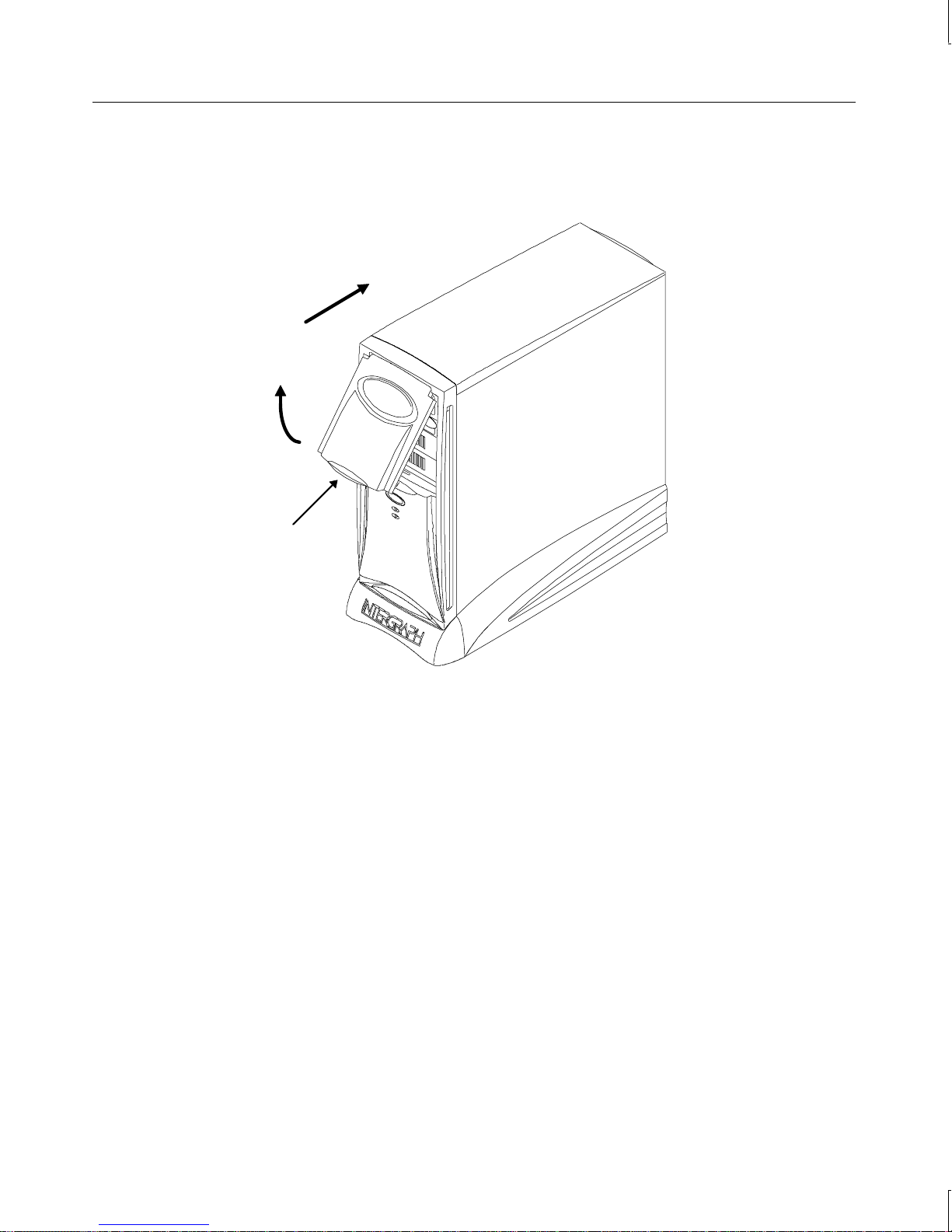
2. Lower the door until it stops and then press gently until the door clicks into the closed
position.
Push Back
Swing Up
Lift Here
53
Starting and Shutting Down the System
After you complete Setup and start the system for the first time, you can start and stop the
system as needed.
To start the operating system:
1. Turn on power to the system.
2. On a system running Windows 95, the operating system starts.
On a system running Windows NT Workstation 4.0, the boot menu displays; select
Windows NT to display the logon dialog.
Page 68

54
To log on to the operating system:
1. If the logon dialog does not display, press
CTRL+ALT+DELETE to display it.
2. Type a username and password into the appropriate boxes.
3. If appropriate, type a domain name.
4. Select OK or press
ENTER.
To log off, restart, or shut down the operating system:
1. Select Shut Down from the Start menu.
2. Perform one of the following steps, as appropriate:
−
To log off the operating system, select the “close all programs” option (if
given), and then select OK.
−
To restart the system, select the restart option, and then select OK.
−
To shut down the system, select the shutdown option, and then select OK.
After shutting down or logging off the operating system, you can turn off the power to the
base unit and monitor.
You can start the system in MS-DOS from the Windows 95 Startup menu. If you do this, the
drivers for the CD-ROM drive and the mouse do not load automatically. To enable use of
the CD-ROM drive and the mouse in MS-DOS, you must load their drivers manually after
the system starts in MS-DOS.
To start the system in MS-DOS from the Windows 95 Start menu:
1. Restart the system.
2. When the message Starting Windows 95 displays, press
F8. The Windows 95
Startup Menu displays.
3. Select the Command Prompt option, and then press
ENTER.
To load the CD-ROM drive and mouse drivers in MS-DOS:
At the MS-DOS command prompt, key in windows\dosstart.bat. This runs
DOSSTART.BAT,
which loads the drivers for the CD-ROM drive and the mouse.
NOTE You need not run DOSSTART.BAT if you put the system into MS-DOS mode from within
Windows 95.
For more information on starting and stopping the operating system, see the operating
system documentation and Help.
Page 69

Observing Operating Precautions
Observe the following precautions when operating the system:
u
When restarting the system, use the operating system controls instead of turning the
power switch off and on. Use the power switch only when instructed, or as the last
alternative for restarting the system.
u
Never turn off power to the base unit when the disk access LED is lit.
u
After turning off power to the base unit, wait at least 30 seconds before turning the
power on again, to ensure that the disk drives have stopped and the system has powercycled properly.
u
Run virus scan software periodically to ensure that your system’s files and programs are
not corrupted.
Using InterSite Programs
55
Your system shipped with several InterSite programs, including the following:
u
InterSite Version Manager is a tool for creating system software backup diskettes, and
for updating device drivers and other system software products installed on the system.
u
InterSite DMI Console gives easy access to the system’s status and configuration
information. The Console is based on the Desktop Management Interface (DMI),
through a window containing a graphical information tree view pane, a service provider
component information pane, and a message pane. Designed for Windows NT, DMI
Console works with the Desktop Management Interface (DMI), a technology standard
that enables the effective management of personal computers.
u
InterSite Hardware Monitor is an easy-to-use interface to instrumentation data measured
by sensors inside the computer. Event information is reported to the Windows NT
Event Log and displayed graphically.
u
InterSite Watchdog is a system monitoring tool with remote monitoring capabilities.
You can install Watchdog on a system running the Windows NT, and use it to monitor
workstations and servers also running Windows NT.
From the operating system Start menu, go to Programs/InterSite to find the InterSite
programs on your system. See the online Help for each InterSite program for more
information on how to use the program.
Page 70

56
Updating an Emergency Repair Disk or a Startup
Diskette
You may have created an Emergency Repair Disk (Windows NT) or a Startup diskette
(Windows 95) during first-time startup, or through InterSite Welcome. If you did not, you
should create the appropriate diskette after you finish configuring the system. If you did, you
should update it any time you change the configuration of the system. The files on the
Windows NT Emergency Repair Disk can restore the original contents of a damaged
operating system Registry (that is, at the time the operating system was installed), along with
the standard operating system drivers. Use the Startup diskette to start the system in the
event you have trouble starting Windows 95.
See the operating system documentation for information on creating an Emergency Repair
Disk or a Startup diskette.
Ensuring PC Card Support and Operation
The optional PC Card adapter is used with devices based on standards developed by the
Personal Computer Memory Card International Association (PCMCIA). Windows NT and
Windows 95 provide support for PC Card devices. See the operating system documentation
and Help for more information on PC Card device support.
If you will be using a PC Card hard disk device (ATA or AT type) with a system running
Windows NT, make sure the device drivers that control PC Card hard disk operation are set
to start correctly. Set the Atdisk device to start as a System device; set the Pcmcia device to
start as a Boot device. Do this before inserting a PC Card hard disk device in the PC Card
adapter. If you do not, anomalous behavior may result -- for example, the PC Card hard disk
drive may not be detected by Windows NT, or may be detected as the system drive (drive C).
NOTE You must shut down the system before inserting a PC Card device in the PC Card adapter.
When you restart the system, Windows NT will recognize the PC Card device.
To change the startup type for device drivers that control PC Card hard disks:
1. Open Devices in the Control Panel. The Devices dialog displays.
2. Highlight the Atdisk device in the Device list; then select Startup. The Device dialog
displays.
3. Under Startup Type, select System; then select OK.
4. Highlight the Pcmcia device in the Device list; then select Startup. The Device dialog
displays.
Page 71

5. Under Startup Type, select Boot; then select OK.
6. In the Devices dialog, select Close.
Windows 95 OSR 2.5 and the Active Desktop
If you purchased a system with Windows 95, it shipped with Windows 95 OEM Service
Release 2.5 (Microsoft Windows 95 4.00.950 C). Windows 95 OSR 2.5 integrates Internet
Explorer version 4.01 into the operating system.
When you start your system for the first time, Internet Explorer installs at the end of
Windows 95 Setup. You will notice that it takes several minutes for Internet Explorer to
complete its installation. After Internet Explorer installs, Active Desktop is enabled by
default.
Active Desktop appears as follows:
u
The desktop displays a black background, with Active Desktop in the lower right
corner.
57
u
An active channel bar displays on the right side of the desktop.
u
The operating system’s desktop menus appear in a browser-style interface.
If you prefer the standard Windows 95 interface, you can disable Active Desktop.
To disable Active Desktop:
1. Right-click the desktop, and then click Active Desktop−Customize my desktop.
2. In the Web tab of the Display Properties dialog, clear the check boxes for View My
Active Desktop as a Web Page and Internet Explorer Channel Bar.
3. You will be prompted that the wallpaper selected can be shown only with Active
Desktop. Select No, I do not want to enable Active Desktop.
4. Click OK.
Accessing the Audio System Mixer
On systems shipped from the factory with a multimedia option, you have quick access to the
audio system’s Mixer program. The Mixer program replaces the default operating system
Volume Control program.
Page 72

58
To display the audio system’s Mixer program, do one of the following:
u
Click the speaker icon on the operating system taskbar.
u
From the Start menu, select Programs/Accessories/Multimedia/Volume Control.
If you reinstall the operating system, or install a system audio option on a system that did not
have it previously, you can set up the quick access feature yourself.
To set up quick access to system audio under Windows NT:
1. Install the driver software for the sound card.
2. In the
3. Copy the
C:\WINNT\SYSTEM32 directory, rename the SNDVOL32.EXE file to SNDVOL32.OLD.
ENSMIX32.EXE file from its installation directory to the C:\WINNT\SYSTEM32
directory.
4. Rename the copied
ENSMIX32.EXE file to SNDVOL32.EXE, and then restart the system.
To set up quick access to system audio under Windows 95:
1. From My Computer, double-click Control Panel.
2. In Control Panel, double-click Add/Remove Programs.
3. In Add/Remove Programs Properties, select the Windows Setup tab.
4. Under Components, double-click Multimedia.
5. Under Components, clear the check box next to Volume Control; then select OK.
6. In Add/Remove Programs Properties, select OK.
7. Install the driver software for the sound card, and then restart the system.
For more information on the audio mixer and other system sound controls, see the online
documentation on the Ensoniq CD-ROM (accompanying the sound card), the operating
system documentation, or Help.
Booting from an External SCSI Disk Drive
If your system has access to an IDE or EIDE drive, it will attempt to boot from the drive. If
you install a SCSI adapter in your system, you can boot the system from an external SCSI
disk drive if you take the following steps.
Page 73

To boot from an external SCSI disk drive:
1. Disconnect any IDE or EIDE disk drives from the primary and secondary IDE
controllers. The system’s BIOS will not accept a mixture of SCSI and IDE/EIDE
devices if the boot device is a SCSI disk drive.
2. Disconnect the CD-ROM drive from the secondary IDE controller and reconnect it to
the primary IDE controller.
3. Configure the BIOS for a SCSI system.
See Chapter 4, “Configuring the BIOS,” for BIOS configuration information. See Chapter
1, “Setting Up the Hardware,” for device connection information.
If the CD-ROM drive does not appear in the Windows NT operating system after booting
from a SCSI disk drive, make sure that the AT Attachment Packet Interface (ATAPI) device
is enabled.
To enable the ATAPI device in Windows NT:
1. Open Devices in the Control Panel. The Devices dialog displays.
59
2. Highlight atapi in the Device list; then select Startup. The Device dialog displays.
3. Under Startup Type, select Boot; then select OK.
4. In the Devices dialog, select Close.
Using Hardware Security Features
The system provides you with security features designed to help prevent unauthorized
tampering with the internal components.
A security tab is located at the top left of the chassis under the top cover. You can place a
small padlock or a security seal in the hole on the tab to prevent removal of the left side
panel.
A tamper-indicating Factory Quality Seal is affixed to the main chassis and left side panel
security tab. The seal is your assurance that the unit has not been opened since it left the
factory. When removed, the word “VOID” appears on the seal. Removing the seal does not
void your warranty.
See the System Reference for details on removing the system’s top cover and side panels.
Page 74

60
Page 75

6 Troubleshooting
Use this chapter to help identify the causes of problems that may occur on a TDZ 2000 GL1
or ExtremeZ GL1 workstation.
See the System Reference for information on opening the case and working with internal
components. If you cannot resolve the problem or if the instructions direct you to call the
Customer Response Center, contact Intergraph Computer Systems. See the Preface of this
document for details.
System Power.................................................................................................................... 62
System Boot....................................................................................................................... 62
Sound ................................................................................................................................65
Video................................................................................................................................. 66
Miscellaneous Hardware.................................................................................................... 66
Network............................................................................................................................. 67
61
Page 76

62
System Power
ERROR - Fails to power on.
Reason
Power cord not connected properly. Verify that the power cord is properly
Power not available at the outlet. Verify power to the outlet has not been
Power not available from the UPS. Verify the UPS is connected and operating
Internal power cables not connected. Open case and ensure all power cables are
Faulty power cord. Replace power cord.
System Boot
ERROR - Does not boot from drive A.
Reason
Corrupt BIOS on the flash EPROM. Power off the system and insert a floppy
Solution
connected to the power receptacle.
interrupted. Test the outlet with a known
working appliance.
properly.
connected.
Solution
diskette containing the
into the floppy disk drive. Depress and
CTRL-HOME while powering up the
hold
system. Release the keys when the drive
LED lights. If the BIOS remains corrupt,
contact the Customer Response Center.
AMIBOOT.ROM file
The boot sequence may be set to C, A, in
which case the machine will not boot from A
if there is an operating system on C.
Corrupt boot disk, or boot disk does not have
correct boot utilities.
Change the boot sequence. See
Chapter 4.
Replace the boot disk. See System
Reference.
Page 77

ERROR - Does not boot from the expected boot device.
63
Reason
Solution
Boot sequence not correctly set. Change the boot sequence. See
Chapter 4.
Operating system not on the system drive. Install the operating system as described in
Chapter 7.
ERROR - Series of beeps and error message displays.
Message
Explanation and Solution
Refresh Failure Bad memory refresh circuitry on the system
board. Remove and reinstall SIMM(s). If
error persists, replace the SIMM(s).
Parity Error Parity error in the first 64 KB block of
memory. Remove and reinstall SIMM(s).
If error persists, replace SIMM(s).
Base 64 KB Memory Error Memory failure in the first 64 KB. Remove
and reinstall the SIMM(s). If error persists,
replace the SIMM(s).
Timer Not Operational Memory failure in the first 64 KB, or Timer
1 on the system board is not functioning.
Call the Customer Response Center.
Processor Error The CPU on the system board generated an
error. Call the Customer Response Center.
8042 - Gate A20 Failure The BIOS cannot switch to protected mode,
or the keyboard controller is
malfunctioning. Call the Customer
Response Center.
Processor Exception Interrupt The CPU generated an exception interrupt.
Call the Customer Response Center.
Display Memory Read/Write Error The video adapter is faulty. Call the
Customer Response Center.
ROM Checksum Error The ROM checksum value does not match
the value encoded in the BIOS. Call the
Customer Response Center.
CMOS Shutdown Register Read/Write
Error
The shutdown register for CMOS RAM
failed. Call the Customer Response Center.
Cache Error/External Cache Bad The external cache is faulty. Call the
Customer Response Center.
Page 78

64
ERROR - CD-ROM drive is not recognized.
Reason
Solution
CD-ROM drive power cable not attached. Open case and ensure power cable is
properly attached. See System Reference.
CD-ROM drive cable not attached. Open case and ensure cable is properly
attached. See System Reference.
ERROR - System hard disk drive not recognized.
Reason
Solution
Hard disk drive power cable not attached. Open the case and ensure power cable is
properly attached. See System Reference.
Hard disk drive SCSI cable not attached. Open the case. Ensure the SCSI cable is
properly attached at both ends. See System
Reference.
A SCSI address conflict exists between the
hard disk drive you installed and another
SCSI device.
Remove the hard disk drive and change
SCSI ID to an unused setting. See the
documentation shipped with the hard disk
drive.
SCSI termination is enabled on the hard
disk drive you installed.
Disable the SCSI termination. See the
documentation shipped with the hard disk
drive.
Some viruses cause the system to not
recognize hard disk drives.
Run a virus scan program that checks the
Master Boot Record. Clear any viruses
detected by the program.
ERROR - “Invalid configuration information for SLOT XX” message displays.
Reason
System is not properly configured to
recognize the new ISA option board.
Solution
Use the Chipset menu parameters in
AMIBIOS Setup to reserve system resources
for the board. See Chapter 4.
Page 79

ERROR - Total amount of memory does not display.
65
Sound
Reason
Faulty SIMM(s). Identify faulty SIMM(s) by swapping
SIMM(s) not properly seated into socket(s). Ensure SIMM(s) are properly installed. See
ERROR - I/O card parity error message displays.
Reason
Faulty option board is installed in ISA slot. Remove ISA board, then restart the system.
ERROR - Sound cannot be heard.
Reason
Volume of speakers on multimedia keyboard
is low or off.
Solution
SIMM(s) until the faulty one is found. See
System Reference.
System Reference.
Solution
See System Reference.
Solution
Adjust volume up, release Mute button or set
slider switch to speaker position on
multimedia keyboard.
Speaker cable is not properly connected. Verify cable is properly connected.
Volume is turned off in the program. Double-click the speaker icon in the taskbar
tray and increase the master volume.
Headphones are plugged into the
multimedia keyboard.
Sound files work properly, but audio CD’s
produce no sound.
Unplug the headphones.
Verify the CD audio cable is connected
between the CD-ROM drive and
motherboard.
Page 80

66
Video
ERROR - System powered on, but screen remains blank.
Reason
Monitor not powered on. Turn on power to the monitor.
Monitor power cord not connected. Connect monitor power cord to AC outlet
Video cable not properly installed. Ensure video cable is connected to monitor
Graphics card not seated properly. Open case and re-seat graphics card. See
Selected resolution is not supported by the
monitor.
Improper video display driver installed. Remove the driver and install a valid driver.
Miscellaneous Hardware
ERROR - CD-ROM drive LED does not light.
Reason
Solution
and monitor.
and case.
System Reference.
Select a supported resolution. See the video
card documentation and
for resolution details.
See Chapter 3.
Solution
README.TXT file
CD-ROM drive power cable not attached. Open case and ensure power cable is
properly attached. See System Reference.
ERROR - Floppy disk drive LED does not light.
Reason
Floppy disk drive power cable not attached. Open case and ensure power cable is
ERROR - Arrow keys or numbers do not work on keyboard number pad.
Reason
NUM LOCK disabled. Press the NUM LOCK key.
Solution
properly attached. See System Reference.
Solution
Page 81

Network
ERROR - Cannot connect to other systems on LAN.
67
Reason
Network cable disconnected. Reconnect network cable and ensure proper
Incorrect software configuration. Notify your System Administrator.
ERROR - Cannot plot to network plotter on LAN.
Reason
Network cable disconnected. Reconnect network cable, ensure proper
Plotter not added to Print Manager on your
system.
Plot node does not recognize your system. Notify your System Administrator.
Solution
connection. If cable is properly connected,
notify your System Administrator.
Solution
connection.
Notify your System Administrator.
Page 82

68
Page 83

7 Installing S ystem Software
Follow the instructions in this chapter if you need to reinstall the operating system and
associated system software on your TDZ 2000 GL1 or ExtremeZ GL1 workstation. Before
you reinstall the software, ensure that you read and understand this entire chapter.
69
NOTE If you are setting up an ExtremeZ workstation for the first time, see the
Welcome Letter
for initial setup of an ExtremeZ workstation. Use the information in this chapter only if you
have to reinstall the operating system and associated system software on your ExtremeZ
workstation.
. The
ExtremeZ Customer Welcome Letter
provides step-by-step instructions
Before You Begin.............................................................................................................. 70
System Software Products.................................................................................................. 70
Drivers and Applications for ExtremeZ Systems ................................................................ 72
Installing Windows NT Workstation 4.0 ............................................................................ 73
Installing the Ensoniq Sound Adapter Driver ....................................................... 74
Disabling Command Queuing .............................................................................. 75
Enabling Bus Mastering for IDE/ATAPI Devices................................................. 75
Installing Windows 95....................................................................................................... 76
Installing the Ensoniq Sound Adapter Driver ....................................................... 78
Installing Windows 95 with an Installed Network Adapter ................................... 78
Installing 3Com Network Adapter Driver Software .............................................. 78
Enabling Bus Mastering for IDE/ATAPI Devices................................................. 79
Updating the Operating System.......................................................................................... 79
ExtremeZ Customer
Page 84

70
Before You Begin
Have the following items available:
u
The information that you recorded in Chapter 2, “Setting Up the Software.”
u
Operating system software CD-ROM, associated Service Packs, diskettes, and
documentation. Make sure you have the Setup diskettes (Windows NT Workstation 4.0)
or the Boot diskette (Windows 95), as appropriate.
u
Backup diskettes you created according to instructions in Chapter 2, “Setting Up the
Software.”
u
Backup diskettes and documentation delivered with any expansion cards or additional
peripheral devices purchased from Intergraph Computer Systems.
u
The Late-Breaking News document delivered with the system.
You can find the system software on backup diskettes that you created, on diskettes provided
by Intergraph Computer Systems, or on the operating system CD-ROM. If you did not create
backup diskettes of drivers or other system software products, they are probably available on
the operating system CD-ROM or on backup diskettes delivered with expansion cards.
NOTE If your system is an ExtremeZ workstation, the system was shipped with the Drivers and
Applications product on the Connectivity Plus CD-ROM. Drivers and Applications is a set of
system drivers and applications specifically for rebuilding an ExtremeZ workstation. For
more information, see “Drivers and Applications for ExtremeZ Systems” in this chapter.
NOTE You must install certain drivers from backup or other diskettes. The correct driver versions
may not be on CD-ROM.
Driver software is routinely improved and updated. Visit the Intergraph Computer Systems
site on the World Wide Web and vendor bulletin boards for new and updated drivers.
Review the Late-Breaking News document delivered with your system for any additional
tasks you may have to perform during reinstallation.
System Software Products
The following table lists drivers and other system software products installed on various
configurations of TDZ 2000 GL1 systems. Names of system software products created by the
InterSite Version Manager or available from the Intergraph online services are listed.
Products available for your system, but not listed here, are available on an operating system
software CD-ROM or are delivered with an expansion card or additional peripheral device.
Page 85

Description Windows NT 4.0 Windows 95 IBBS
71
Accel Graphics AccelSTAR II
ACCEL2DRVNT ACCEL2DRV95
video driver
Matrox Millennium II
MILL2DRVNT MILL2DRVW95
video driver
Intense 3D Pro 2200 video
INTENSEDRV
−
driver
Ensoniq AudioPCI audio card
ENSONIQDRV ENSONIQW95DR
driver
Primax mouse driver
−
IKON PCI driver IKONPCIDRV
3COM 3C900 network adapter
3COM3C900 3COM3C900
PMOUSE
−
driver
Intel PRO 100B network adapter
INTELPRO100B INTELPRO100B
driver
OLICOM Token Ring network
PCITOKRNG PCITOKRNG
adapter driver
56KB modem driver 56KMODEM 56KMODEM
Adaptec SCSI adapter driver 2940SCSIDRV 2940SCSI95
SMART Drive driver SMARTDRV
−
Diskeeper Lite DKLITE
−
InterSite Welcome WELCOME WELCOME
InterSite Version Manager VERMANAGER VERMANAGER
InterSite Hardware Monitor
InterSite Watchdog WATCHDOG
InterSite Manager IM
InterSite DMI Console DMI
IE 4.01 Settings file
Windows 95 Boot Floppy
Windows NT 4.0 Service Pack 3 SP3
Quick-Fix Engineering Update QFE_NTW
BIOS and Flash Program Utility
HWMON_TD220
−
−
−
−
−
−
IE4SETTINGS
BOOTW95R2
−
−
−−
System Introduction DFXSYSIN DFXSYSIN
FLASHUTIL
Page 86

72
Drivers and Applications for ExtremeZ Systems
If you have an ExtremeZ system, it was shipped with the Drivers and Applications product
on the Connectivity Plus CD-ROM. Drivers and Applications is a set of system drivers and
applications specifically for rebuilding an ExtremeZ workstation. When this document
instructs you to install a driver from backup diskette, use the Connectivity Plus CD-ROM
instead, and type the path name for the driver as follows:
drive:\drivers and apps\directory
where drive is the drive letter for your system’s CD-ROM drive, and directory is the
directory name you want to use. Select from the following drivers and applications:
Directory
PMOUSE Primax mouse driver
DMI InterSite DMI Console
INTELPRO100B Intel PRO/100B network adapter driver
2940SCSI95 Adaptec SCSI adapter driver
INTELNETDRV Intel 82557-based PCI EtherExpress network driver
MILL2DRVNT Matrox Millennium II video driver
QFE_NTW Quick-Fix Engineering Update software
SMARTDRV InterSite SMART-capable disk driver
VERMANAGER InterSite Version Manager
WATCHDOG InterSite Watchdog
WELCOME InterSite Welcome
IM InterSite Manager
DKLITE Diskeeper Lite
Description
Page 87

Installing Windows NT Workstation 4.0
Depending on your system’s configuration, you will need some or all of the following system
software during the installation process:
u
SCSI adapter driver
u
Video display adapter driver
u
Network adapter driver
u
Sound adapter driver
u
QFE update software
Follow the instructions in Start Here to install Windows NT.
Do the following during installation of the operating system:
u
Select Custom Setup when prompted to select a Setup type.
73
u
On a system with internal SCSI disk drives and a SCSI adapter, press the S key to install
the SCSI adapter driver from backup diskette. Select Other (Requires disk
provided by a hardware manufacturer) from the list and press
ENTER. Insert
the diskette with the SCSI adapter driver into the floppy disk drive, and then press
ENTER.
u
Specify a driver for the CD-ROM drive by pressing the S key and then selecting IDE
CD-ROM (ATAPI 1.2)/ PCI IDE Controller from the list.
u
On single-processor systems, when prompted, select Standard PC. This will load the
single-processor kernel and HAL, providing better performance. On dual-processor
systems, if prompted, select MPS Multiprocessor. This will load the multi-processor
kernel and HAL, enabling the system to take advantage of the second processor.
u
Allow Setup to configure the network only if you have an installed network adapter, and
only if the system is connected to the network.
u
Create an Emergency Repair Disk when prompted to do so.
Do the following after installation of the operating system:
u
Install drivers or other system software from any backup diskettes. System software
delivered on backup diskette is usually more current than system software on the
operating system CD-ROM. Alternatively, you can install the drivers or other system
software from the Windows NT CD-ROM if you do not have them on diskette.
u
Perform any additional installation and configuration tasks described in the LateBreaking News document delivered with your system.
u
Configure the system as described in Chapter 3, “Configuring the System.”
Page 88

74
u
If your system was running Windows NT 4.0 Service Pack software, install this software
after installing drivers and other system software, and after installing any application
software products.
u
Perform any operational changes required for your system as described in Chapter 4,
“Operating Notes.”
Do the following after you install the Windows NT Service Pack:
u
If you created a Quick-Fix Engineering (QFE) backup diskette from Version Manager
during any previous initial system configuration, install the QFE update software. See
README.TXT file on the QFE diskette for more information.
the
u
Complete the additional installation and configuration tasks in this section.
Installing the Ensoniq Sound Adapter Driver
Systems with an audio option include an Ensoniq sound card. The Ensoniq sound card is
delivered with a software CD-ROM that contains driver software, wavetable and mixer
software, and online documentation for installing and using the sound card. However, the
online Ensoniq documentation does not describe how to install the software on a system
running Windows NT 4.0 -- for example, if you must reinstall the operating system, or if you
add a system audio option.
To install the Ensoniq driver, wavetable, and mixer software:
1. Insert the Ensoniq software CD-ROM into the system’s CD-ROM drive.
2. From the Start menu, go to Settings/Control Panel/Multimedia/Devices (tab); then click
Add..
3. In the Add dialog, in the List of Drivers, click Unlisted or Updated Driver; then click
OK.
4. In the Install Driver dialog, type the path to the Windows NT software on the CD-ROM;
then click OK. The Windows NT software can be found on the CD-ROM at
\winnt\language\cd, where language is the language of the operating system (for
example, english).
5. After the software has been installed, in the Add Unlisted or Updated Driver dialog,
select Ensoniq AudioPCI; then click OK.
6. When the configuration dialog displays, click OK to accept the default settings.
7. In the Multimedia Properties dialog, click OK.
8. Remove the CD-ROM from the system; then restart the system.
After you install the software, see Chapter 4, “Operating Notes,” to set up quick access to
system audio through the Taskbar or the Start menu.
Page 89

75
Disabling Command Queuing
To improve standalone system performance and to improve performance with some highperformance SCSI peripherals, you should disable command queuing in the Windows NT
Registry.
WARNING Do not change values in the Registry other than as directed. If you introduce incorrect
values into the Registry, you may cause serious operating system problems, and you
may have to reinstall Windows NT. If you change values in the Registry that make
your system unusable, you may be able to restart the system and use the Last Known
Good Configuration option to undo the damage. See the operating system
documentation for more information on the Last Known Good Configuration option.
To disable command queuing:
1. Start the Registry Editor (
REGEDT32.EXE) to open the Registry.
2. Open the following subkey in the Registry:
HKEY_LOCAL_MACHINE\SYSTEM\CurrentControlSet\Services\aic78xx
3. From the Edit menu, select Add Key.
4. Type Device into the Key Name box, and then select OK. Do not set a Class value.
5. Open the following subkey in the Registry:
HKEY_LOCAL_MACHINE\SYSTEM\CurrentControlSet\Services\aic78xx\
Device
6. From the Edit menu, select Add Value.
7. Type DisableTaggedQueuing into the Value Name box.
8. Select REG_DWORD for the Data Type, and then select OK.
9. Type 1 into the Data box.
10. Set the Radix value to Hex, and then select OK.
11. Exit from the Registry Editor and restart the system.
Enabling Bus Mastering for IDE/ATAPI Devices
Your system shipped with bus mastering for IDE/ATAPI devices enabled. If you reinstall
Windows NT 4.0 and Service Pack 3 software, you should enable IDE/ATAPI bus mastering.
NOTE If you have a CD-Recorder drive installed, do not enable IDE/ATAPI bus mastering. The CD-
Recorder drive is incompatible with IDE/ATAPI bus mastering.
Page 90

76
To enable IDE/ATAPI bus mastering:
1. Ensure that the operating system, Service Pack 3 software, and QFE update software
QFE_NTW) are installed.
(
NOTE The QFE update software includes an updated ATAPI device driver that should be installed
after Service Pack 3.
NOTE For reasons of system performance, if a TR-4i tape drive or a Zip drive is installed, do not
enable DMA use on the IDE channel to which the drive is connected. A TR-4i tape drive or
Zip drive is usually connected to Channel 0 when installed at the factory.
2. Insert the Windows NT 4.0 Service Pack 3 CD-ROM into your system’s CD-ROM drive.
3. In Explorer or File Manager, navigate to the \
4. Double-click
DMACHECK.EXE. The ATAPI DMA support dialog displays.
5. The Current DMA Usage boxes indicate which channels have IDE/ATAPI devices. For
each channel with an IDE/ATAPI device, click Enabled; then click OK.
6. Restart the system.
Installing Windows 95
Depending on your system’s configuration, you will need some or all of the following system
software during the installation process:
u
Windows 95 Operating System Service Release 2.5
u
SCSI adapter driver
u
Video display adapter driver
u
Network adapter driver
u
Sound card driver
u
Mouse driver
SUPPORT\UTILS\I386 directory.
When reinstalling Windows 95, you must also reinstall various system software products
during and after operating system Setup.
You can create backup diskettes for these products using InterSite Version Manager.
See Chapter 2, “Setting Up the Software,” for more information on using InterSite Version
Manager to create system software backup diskettes.
To install Windows 95:
1. Insert the Windows 95 boot diskette in the floppy disk drive.
Page 91

2. Insert the Windows 95 CD-ROM in the CD-ROM drive.
3. Start (or restart) the system.
4. At the Windows 95 Startup Menu, select the option to install Windows 95.
If you are installing Windows 95 on a system on which another operating system or a
previous version of Windows 95 exists, you may have to partition and format the system’s
hard disk before installing Windows 95. An option on the Startup Menu allows you to exit
to MS-DOS and use the fdisk and format commands.
CAUTION Be sure to make a backup copy of your data and/or programs before partitioning and
formatting the system’s hard disk. All data on the hard disk will be destroyed during the
fdisk and format process. Once you have completed these tasks and reinstalled Windows
95, you must reinstall any application software and data that you want to use.
CAUTION Make sure that all disk drives attached to the system are partitioned, and formatted with the
File Allocation Table (FAT) file system, before attempting to install Windows 95, or the
installation will fail.
77
Follow the instructions in Introducing Windows 95 to install Windows 95. As you install the
operating system:
u
Select the default responses during the Setup process.
u
Allow Setup to configure the network only if you have an installed network adapter, and
only if the system is connected to the network.
u
Create a Startup diskette when prompted.
u
While Windows 95 files are being copied to the system, you are prompted for the
Windows 95 Setup boot diskette. This occurs even if the Windows 95 Setup boot
diskette is already inserted in the floppy disk drive. Select OK to continue.
Next, you are notified that a CD-ROM driver file (such as MTMCDAI.SYS or
TAISATAP.SYS) could not be found on the Windows 95 Setup boot diskette. In the dialog
that displays, specify that the file should be copied from a:\, and then select OK.
After installing the operating system:
u
Install drivers or other system software from any backup diskettes. System software
delivered on backup diskette is usually more current than system software on the
operating system CD-ROM. Alternatively, you can install the drivers or other system
software from the Windows 95 CD-ROM if you don’t have them on diskette.
As shipped from the factory, the system’s hard disk drive contains Windows 95 Setup
files in the
C:\WINDOWS\OPTIONS\CABS directory, as compressed .CAB files. If the CABS
directory is deleted from the system’s hard disk, you must have access to a Windows 95
CD-ROM to use Windows 95 Setup files.
Page 92

78
u
Perform any additional installation and configuration tasks described in the LateBreaking News document delivered with your system.
u
Configure the system as described in Chapter 3, “Configuring the System.”
u
Perform any operational changes required for your system as described in Chapter 4,
“Operating Notes.”
u
You can install MS-DOS Microstation drivers, available from the Intergraph Bulletin
Board Service (IBBS).
Installing the Ensoniq Sound Adapter Driver
Systems with an audio option include an Ensoniq sound card. The Ensoniq sound card is
delivered with a software CD-ROM that contains driver software, wavetable and mixer
software, and online documentation for installing and using the sound card. To install the
Ensoniq driver, wavetable, and mixer software, see the online documentation on the Ensoniq
software CD-ROM.
After you install the software, see Chapter 4, “Operating Notes,” to set up quick access to
system audio through the Taskbar or the Start menu.
Installing Windows 95 with an Installed Network Ad apter
If you reinstall Windows 95 on a system with an installed network adapter, the adapter may
not function after completing Setup.
To re-enable network adapter operation after installing Windows 95:
1. Go to Start/Settings/Control Panel/System/Device Manager.
2. In the list of devices displayed, double-click Other Devices.
3. Under Other Devices, click the network adapter installed in your system, and then click
Remove.
4. Close Device Manager, and then restart the system.
5. As Windows 95 starts, it should detect the network adapter and prompt you to install the
network adapter’s driver software. Follow the instructions displayed. You will need the
diskette containing the network adapter’s driver software.
Installing 3Com Network Adapter Driver Software
If your system includes a 3Com network adapter, the driver software is not preinstalled. The
first time Windows 95 starts, it detects the 3Com network adapter and prompts you for the
Page 93

79
driver software. Install the driver software from the 3COM3C90X diskette, which is delivered
as backup media in InterSite Version Manager or in the 3Com network adapter kit.
Enabling Bus Mastering for IDE/ATAPI Devices
Your system shipped with bus mastering for IDE/ATAPI devices enabled. If you reinstall
Windows 95, you should enable IDE/ATAPI bus mastering.
NOTE If you have a CD-Recorder drive installed, do not enable IDE/ATAPI bus mastering. The CD-
Recorder drive is incompatible with IDE/ATAPI bus mastering.
To enable IDE/ATAPI bus mastering:
1. Go to Start/Settings/Control Panel/System/Device Manager/Disk Drives.
2. Click a disk drive, then click Properties, and then click Settings.
3. Click the DMA check box, and then click OK.
4. Repeat steps 2 and 3 for any additional disk drives.
5. In Device Manager, click the CD-ROM drive, then click Properties, and then click
Settings.
6. Click the DMA check box, and then click OK.
7. Restart the system.
Updating the Operating System
Microsoft Service Packs and Service Releases contain the latest improvements and system
fixes for Microsoft operating systems. Service Packs and Releases are created by Microsoft
for post-release support. You can obtain them from Microsoft’s World Wide Web and FTP
sites free of charge.
CAUTION If Intergraph provides a Service Pack or Service Release through the IBBS or with a product
or system, it has been certified against Intergraph hardware as described in the
announcement of its availability. If you obtain a Service Pack or Service Release from any
other source, be aware that it may not be certified against your Intergraph hardware.
Page 94

80
Page 95

8 Using System Resources
This chapter provides information on using system resources, such as interrupt requests
(IRQs) and basic input/output system (BIOS) parameter settings, to configure the system to
use additional option boards. The chapter covers specific Peripheral Component
Interconnect (PCI) and Industry Standard Architecture (ISA) devices offered by Intergraph
as system options. Intergraph Computer Systems has determined that the devices discussed
in this chapter require specific resource settings to ensure proper system operation.
See Chapter 4, “Configuring the BIOS,” for information on running the BIOS Setup
program and changing BIOS parameter settings.
See the System Reference for additional information on system resources.
System Resources............................................................................................................... 82
ISA Bus Interrupt (IRQ) Assignments .................................................................. 82
Direct Memory Access (DMA) Channels.............................................................. 82
Input/Output (I/O) Addresses ............................................................................... 82
Memory Addresses............................................................................................... 84
Using System Resources..................................................................................................... 84
PCI Devices....................................................................................................................... 85
Ultra SCSI Systems............................................................................................................ 85
81
Page 96

82
System Resources
The following sections list the available system resources. See the vendor documentation
delivered with an expansion card or a peripheral device for instructions on how to use these
resources.
ISA Bus Interrupt (IRQ) Assignments
IRQ System Resource IRQ System Resource
0 Reserved (interval timer) 8 Real time clock
1 Reserved (keyboard) 9 Open / PIRQ mapping
2 Reserved (interrupt controller) 10 Open
3 Serial port COM2 (default) 11 Open
4 Serial port COM1 (default) 12 PS/2 mouse port
5 USB 13 Reserved (math coprocessor)
6 Floppy disk controller 14 Primary IDE controller or open
7 Parallel port LPT1 (default) 15 Secondary IDE controller or open
Direct Memory Access (DMA) Channels
Channel Assignment Channel Assignment
0 Open 4 DMA controller
1 Open 5 Open
2 Floppy disk controller 6 Open
3 Open 7 Open
Input/Output (I/O) Addresses
Address (hex) Description
0000-000F Direct memory access controller
0020-0021 Programmable Interrupt controller
0040-0043 System timer
0060-0060 Standard 101/102-key or Microsoft Natural keyboard
0061-0061 System Speaker
0064-0064 Standard 101/102-key or Microsoft Natural keyboard
0070-0071 System CMOS/real time clock
0080-0090 Direct memory access controller
Page 97

Address (hex) Description
0094-009F Direct memory access controller
00A0-00A1 Programmable interrupt controller
00C0-00DE Direct memory access controller
00F0-00FF Numeric data processor
0170-0177 Tyan 32-Bit PCI EIDE bus master driver
0170-0177 Secondary PCI bus master EIDE driver (dual FIFO)
01F0-01F7 Tyan 32-Bit PCI EIDE bus master driver
01F0-01F7 Primary PCI bus master EIDE driver (dual FIFO)
0295-0296 Motherboard resources
02F8-02FF Communications port (COM2)
0376-0376 Tyan 32-Bit PCI EIDE bus master driver
0376-0376 Secondary PCI bus master EIDE driver (dual FIFO)
0378-037B Printer port (LPT1)
83
037C-037F Motherboard resources
03B0-03BB Cirrus Logic 5430/40 PCI
03C0-03DF Cirrus Logic 5430/40 PCI
03F0-03F5 Standard floppy disk controller
03F6-03F6 Tyan 32-Bit PCI EIDE bus master driver
03F6-03F6 Primary PCI bus master EIDE driver (dual FIFO)
03F7-03F7 Standard floppy disk controller
03F8-03FF Communications port (COM1)
04D0-04D1 Motherboard resources
0CF8-0CFF Motherboard resources
B000-BFFF DEC 21052 PCI to PCI bridge
CF00-CF3F PCI Multimedia audio device
D2A0-D2A7 Motherboard resources
D2B0-D2B7 Motherboard resources
FFA0-FFA7 Tyan 32-Bit PCI EIDE bus master driver
FFA0-FFA7 Primary PCI bus master EIDE driver (dual FIFO)
FFA8-FFAF Tyan 32-Bit PCI EIDE bus master driver
FFA8-FFAF Secondary PCI bus master EIDE driver (dual FIFO)
Page 98

84
Memory Addresses
Address Range (hex) Size Assignment
00000000-0009FBFF 640 KB System board extension for PnP BIOS
0009FC00-0009FFFF 1 KB System board extension for PnP BIOS
000A0000-000AFFFF 64 KB Cirrus Logic 5430/40 PCI
000B0000-000BFFFF 64 KB Cirrus Logic 5430/40 PCI
000C0000-000C7FFF 32 KB Unavailable for use by devices
000E0000-000FFFFF 128 KB System board extension for PnP BIOS
00100000-07FFFFFF 128 MB System board extension for PnP BIOS
FA800000-FC8FFFFF 32 MB DEC 21052 PCI to PCI bridge
FB000000-FBFFFFFF 16 MB Cirrus Logic 5430/40 PCI
FCA00000-FEAFFFFF 33 MB DEC 21052 PCI to PCI bridge
FEAF8000-FEAFFFFF 32 KB Standard PCI graphics adapter
FEC00000-FEC00FFF 4 KB System board extension for PnP BIOS
FEE00000-FEE00FFF 4 KB System board extension for PnP BIOS
FFFE0000-FFFFFFFF 128 KB System board extension for PnP BIOS
Using System Resources
Most ISA devices installed in the system require you to reserve an IRQ. PCI devices also
need to use an IRQ, but since they share system resources they can use the same IRQ. At
least one IRQ must be left unassigned, for use with any PCI devices installed in your system.
The system has a limited number of open IRQs. To install more ISA devices than you have
open IRQs, you must disable one unused system port for each excess ISA device, unless the
device does not require an IRQ.
To reserve an IRQ for an installed device:
1. Restart the system and start the BIOS Setup program.
2. On the PCI/PnP screen, select the IRQ you want to reserve.
3. Change the setting for the selected IRQ to ISA/EISA.
4. Save the changes and exit from the BIOS Setup program.
Page 99

The following expansion cards require specific system resource settings, as noted:
85
Expansion card
(installed in the system)
First modem (Windows NT) COM3, IRQ 4 Disable serial port 1 (COM1);
Second modem (Windows NT) COM2, IRQ 3 Disable serial port 2 (COM2);
First parallel printer adapter Base address 278 None
Second parallel printer adapter Base address 3BC None
3Com network adapter IRQ 10 (default) Reserve IRQ 10
On a system running Windows 95, ensure the following system resources are set as noted:
System resource
Plug and Play operating system On the PCI/PnP screen, set Plug and Play Aware O/S
Serial port 1 COM1 Reserve IRQ 4 (if port is to be used)
Serial port 2 COM2 Reserve IRQ 3 (if port is to be used)
Parallel port LPT1 Reserve IRQ 7 (if port is to be used)
Resources
required
BIOS Setup parameter settings
to Yes
BIOS Setup
parameter settings
reserve IRQ 4
reserve IRQ 3
PCI Devices
The system’s PCI expansion slots comply with the PCI 2.1 specification. Devices that
comply with the PCI 2.1 specification are fully plug-and-play. You do not have to configure
them after installation.
Some older PCI device drivers cannot share an interrupt, which is a violation of the PCI 2.1
specification. If you install a device that uses such a driver, you must free an IRQ for the
device to work in the system.
Ultra SCSI Systems
The optional Adaptec AHA-2940 SCSI adapter card comes with Ultra SCSI mode disabled
by default. If you want to enable Ultra SCSI mode, you must use the SCSISelect Utility to
make the change.
To enable Ultra SCSI mode:
1. Restart the system. During the reboot, press
CTRL+A to start the SCSISelect Utility.
Page 100

86
2. Select Configure/View Host Adapter Settings.
3. Select Advanced Configuration Options.
4. Select Support for Ultra SCSI Speed.
5. Change the value Disabled to Enabled.
6. Press
ESC twice to exit the SCSISelect Utility.
7. In the Save Changes Made dialog, select Yes.
8. Press
ESC.
9. In the Exit Utility dialog, select Yes.
10. Press any key to reboot.
See the SCSI adapter documentation delivered with the system for more information on
using the SCSISelect Utility.
 Loading...