

Page 1

ErgoView Stand
Installation Guide
March 1998
DFED3607M
Page 2

Copyright
1998 Intergraph Computer Systems. All rights reserved. This document contains information protected by copyright, trade secret, and trademark
law. This document may not, in whole or in part, be reproduced in any form or by any means, or be used to make any derivative work, without written
consent from Intergraph Computer Systems.
Use, duplication, or disclosure by the United States Government is subject to restrictions as set forth in subdivision (c)(1)(ii) of the rights in technical
data and computer software clause at DFARS 252.227-7013. Unpublished rights are reserved under the copyright laws of the United States.
Intergraph Computer Systems, Huntsville AL 35894-0001
Notice
Information in this document is subject to change without notice and should not be considered a commitment by Intergraph Computer Systems.
Intergraph Computer Systems shall not be liable for technical or editorial errors in, or omissions from, this document. Intergraph Computer Systems
shall not be liable for incidental or consequential damages resulting from the furnishing or use of this document.
All warranties given by Intergraph Computer Systems about equipment or software are set forth in your purchase contract. Nothing stated in, or
implied by, this document or its contents shall be considered or deemed a modification or amendment of such warrantites.
Trademarks
Intergraph and the Intergraph logo are registered trademarks of Intergraph Corporation. ErgoView is a trademark of Intergraph Corporation. Other
brands and product names are trademarks of their respective owners.
Page 3

Contents
1 ErgoView Stand Installation....................................................................................1
2 Unpacking the Digitizing Table and Base...............................................................2
3 Unpacking the ErgoView Stand ..............................................................................4
4 Installing the Monitor..............................................................................................5
CLIX Workstation Monitor............................................................................................5
Hitachi OEM Monitor....................................................................................................6
Panasonic OEM Monitor ...............................................................................................8
5 Connecting the Cables ........................................................................................... 15
Single ErgoView Stand................................................................................................15
Dual ErgoView Stands.................................................................................................18
Removing the Swivel Base...............................................................................5
Installing a 19-, 20-, or 21-inch Monitor ..........................................................5
Installing a 27-inch Monitor ............................................................................5
Removing the Swivel Base...............................................................................6
Attaching the Adapter Bracket .........................................................................6
Replacing the Monitor Collar...........................................................................7
Installing the Monitor ......................................................................................7
Preparing the Monitor for Installation ..............................................................9
Replacing the Monitor Collar.........................................................................12
Installing the Monitor ....................................................................................13
6 Replacing a CLIX Workstation Monitor..............................................................20
Page 4

Page 5

1 ErgoView Stand Installation
This document describes how to install single- or dual-monitor ErgoView workstation stands with
digitizing table configurations. Read all of the instructions completely before beginning the
installation.
WARNING The following procedures are to be performed by Intergraph Computer Systems service
personnel only, and are not intended for use by customers.
This document describes cable kit installations to make either an Intergraph Computer Systems or
Hamilton table base compatible with the ErgoView stand. The ErgoView stand provides the
mechanical structure to support the following monitors:
19-inch MDSP090, MDSP099, MESAJ44, MDSP102
20-inch MDSP126
21-inch MDSP108, MDSP127, MDSP131, MDSP139, MDSP142, MDSP147
27-inch MDSP072, MDSP097, MDSP098
CAUTION Damage may occur to this equipment if installed in a factory or shop environment where oil, dust, or
other airborne contaminants are present.
1
To unpack and install the digitizing table, ErgoView stand, and monitor, you will need the help of
one person, and the following tools and equipment:
u
Hand truck
u
Diagonal cutting pliers
u
Single-slot screwdriver
u
Adjustable wrench
u
No. 1 Phillips screwdriver
u
No. 2 Phillips screwdriver
u
Socket wrench (1/4 or 3/8-inch drive) and 9/16-inch socket
u
Sharp knife
Page 6
2
2 Unpacking the Digitizing Table and Base
The digitizing table and base are shipped already assembled together. If your installation site has an
existing digitizing table with an Intergraph Computer Systems or Hamilton table base, go to
“Unpacking the ErgoView Stand.”
WARNING To avoid injury, stand to the side when cutting the package banding.
CAUTION Do not penetrate packaging with sharp instruments.
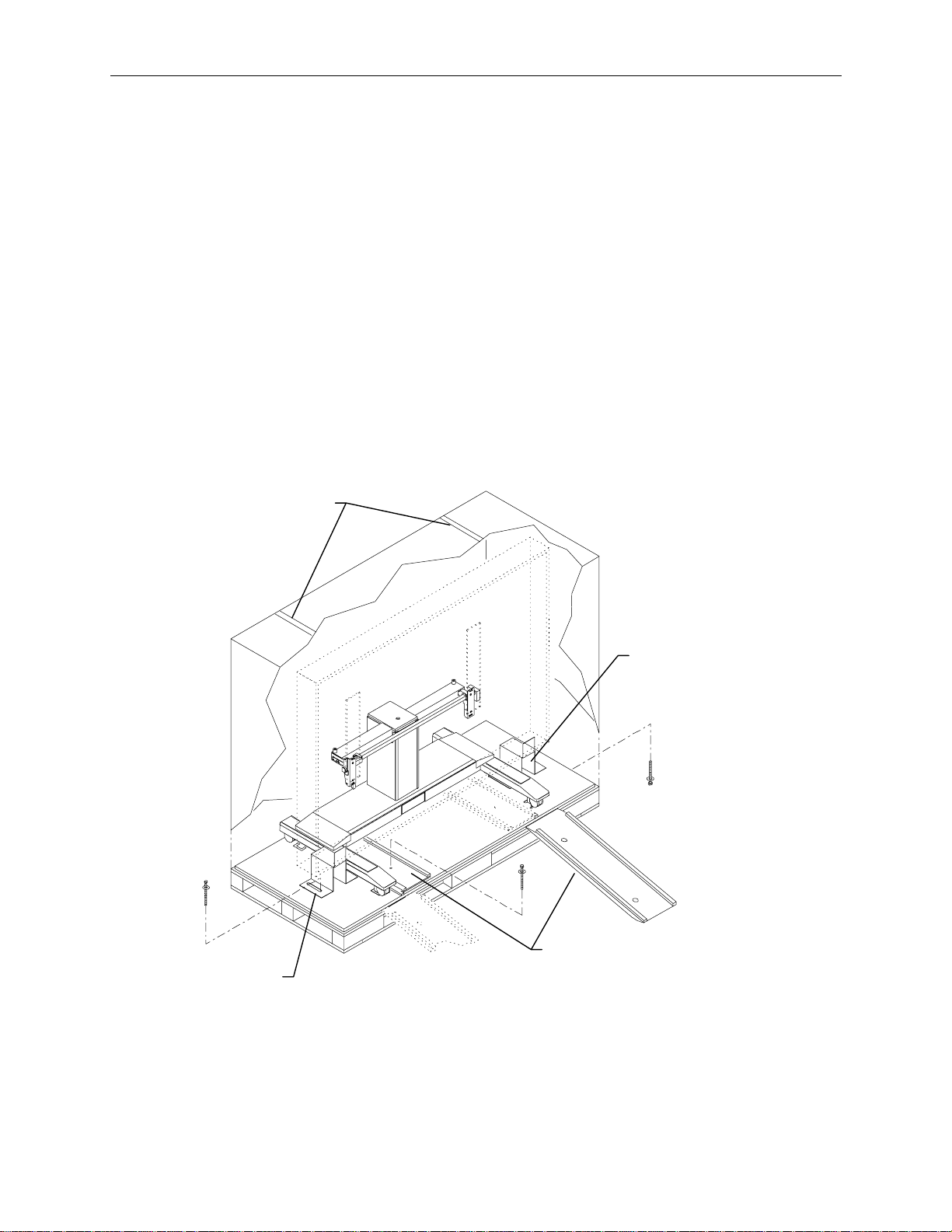
1. Carefully cut the package bands around the box and pallet. See the following figure.
2. Lift the box off the pallet.
3. Remove the plastic wrap from the table base.
WARNING The digitizing table is top-heavy and can tip over while locked in a vertical position.
4. Using a socket wrench with a 9/16-inch socket, remove the hex head bolts that secure the table
brackets to the pallet.
Bands
Table
Bracket
Table
Bracket
5. Unlock the table tilt mechanism (located underneath the table) by moving the handle of the tilt
mechanism towards the center of the table. Rotate the digitizing table to a horizontal position.
6. Lock the table in the horizontal position by moving the handle of the tilt mechanism towards the
outside of the table. Remove the table brackets.
Ramps
Page 7

7. Remove the four bolts that secure the table base to the pallet. The bolts are accessible from
underneath the pallet.
8. Remove the wooden blocks from underneath the legs of the table base.
9. Remove the two bolts that secure the ramps to the pallet.
10. Slide the ramps from under the digitizing table base. Mount the ramp tabs into the slots at the
front of the pallet.
11. With a person at each side of the table, carefully roll the digitizing table down the ramps.
12. Place the digitizing table in the area where you will be installing the ErgoView stand.
WARNING Do not connect the power cable to the AC power outlet at this time.
See “Unpacking the ErgoView Stand” to continue.
3
Page 8

4
3 Unpacking the ErgoView Stand
WARNING To avoid injury, stand to the side when cutting the package banding.
1. Carefully cut the package banding around the box and pallet.
2. Lift the box off the pallet.
3. Remove the plastic wrap from the stand.
4. Using a socket wrench and a 9/16-inch socket, remove the four hex head bolts securing the stand
to the pallet. The bolts are accessible from underneath the pallet.
5. Remove the wooden blocks from underneath the legs of the stand.
6. Using a socket wrench and a 9/16-inch socket, remove the bolts securing the ramps to the pallet.
7. Slide the ramps off the pallet and mount them into the slots at the front of the pallet.
8. With a person at each side of the stand, carefully roll the stand down the ramps.
9. Place the stand near a wall outlet. Allow 36 inches of clearance at the back of the stand for
operator and service access.
WARNING Do not connect the power cable to the AC power outlet at this time.
CAUTION The ErgoView stand must be connected to an unobstructed AC power wall outlet.
See “Installing the Monitor“ to continue.
Page 9

4 Installing the Monitor
Some monitors are shipped with the swivel bases installed. If so, you must remove the swivel base
before installing the monitor into the ErgoView stand.
CLIX Workstation Monitor
Removing the Swivel Base
WARNING The monitor is heavy and could cause serious personal injury if dropped. Two persons should
lift and carry the monitor.
1. Unpack the monitor from its shipping carton.
2. Verify that the monitor power cord is supplied.
3. Turn the monitor onto its side.
WARNING Do not set the monitor on its display screen. Damage may result.
4. Remove the two Phillips screws which have washers beneath them from the swivel base.
5
5. Rotate the swivel base to expose two of the four M5 Phillips pan head screws. Remove the two
screws, rotate the base 180 degrees, and remove the remaining two screws.
6. Remove the swivel base.
Installing a 19-, 20-, or 21-inch Monitor
1. Lock the ErgoView stand tilt adjustment knob, located where the monitor collar attaches to the
ErgoView stand.
2. Set the monitor into the collar.
WARNING Ensure that one person holds the top of the monitor to prevent it from tipping downward when
initially placed in the monitor collar.
3. Thread the four M5x25mm Phillips flat head screws through the bottom of the cover plate
(attached to the bottom of the collar) and into the monitor housing.
4. Tighten all screws.
See “Connecting the Cables” to finish setting up the ErgoView stand.
Installing a 27-inch Monitor
1. Lock the ErgoView stand tilt adjustment knob, located where the monitor collar attaches to the
ErgoView stand.
2. Locate the two screws in the upper corners of the back of the monitor. Remove the outer screw
from each of these corners.
3. Set the monitor into the collar and align the screw holes with the tabs extending from the top of
the collar.
WARNING Ensure that one person holds the top of the monitor to prevent it from tipping downward when
initially placed in the monitor collar.
Page 10

6
4. Thread the two M3x12mm Phillips pan head screws with M4 oversized washers through the
collar tabs and into the monitor housing. Do not tighten the screws yet.
5. Thread the four M5x25mm Phillips flat head screws through the bottom of the cover plate
(attached to the bottom of the collar) and into the monitor housing.
6. Tighten all screws.
See “Connecting the Cables” to finish setting up the ErgoView stand.
Hitachi OEM Monitor
The hardware kit (MKIT120) used to install the Hitachi monitor contains the following items:
u
One monitor cover plate, CFAB329E
u
One pivot cover, CFAB331E
u
One adapter bracket, CFAB330F (MDSP139)
u
One adapter bracket, CFAB250G (MDSP147)
u
One rear bracket, CFAB331F
u
OEM monitor collar, MMSA3530
u
Six M4x8mm screws, CPHM022
u
One-inch foam tape CPTP076 (for CFAB329E)
u
Three-quarter-inch adhesive tape CPTP077 (for CFAB331E)
Removing the Swivel Base
WARNING The monitor is heavy and could cause serious personal injury if dropped. Two persons should
lift and carry the monitor.
1. Unpack the monitor from its shipping carton.
2. Verify that the monitor power cord is supplied.
3. Turn the monitor onto its side.
WARNING Do not set the monitor on its display screen. Damage may result.
4. Rotate the base until the two screws can be seen.
5. Remove and retain the two screws.
6. Slide the base to the back of the monitor and set the base aside.
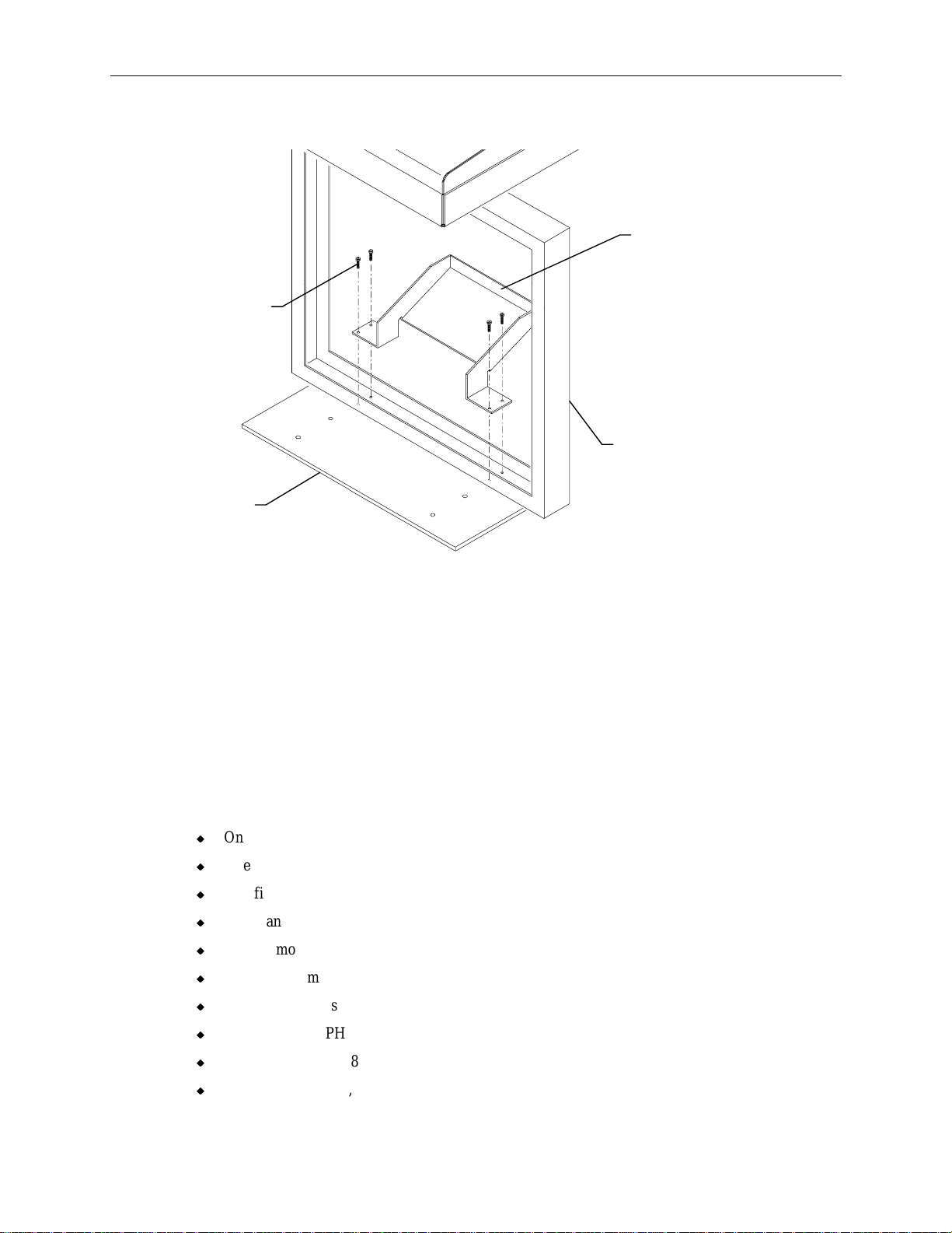
Attaching the Adapter Bracket
1. Place the appropriate adapter bracket onto the bottom of monitor. Ensure the holding latches are
secured inside the slots in the monitor frame. See the following figure.
Page 11

Adapter
Bracket
7
Screws (2)
2. Secure the adapter bracket to the monitor using the two screws removed from the swivel base.
Holding
Latch
Replacing the Monitor Collar
The monitor collar shipped on the ErgoView stand is designed for CLIX workstation monitors only.
You must replace this collar with the one in the mounting kit before installing the Hitachi OEM
monitor.
1. Remove the tilt adjustment knob, located where the monitor collar attaches to the ErgoView
stand.
2. Using retaining ring pliers, remove a retaining ring and the hinge pin from the collar.
3. Remove the collar from the stand.
4. Set the new collar into the stand.
5. Attach the hinge pin and retaining ring.
6. Replace the tilt adjustment knob.
7. Using the 3/4-inch adhesive tape (CPTP077), attach the cover plate (CFAB329E) to the
underside of the aluminum plate extending from the bottom of the new collar.
CAUTION Ensure the new collar is completely secure in the stand before installing the OEM monitor.
Installing the Monitor
1. Lock the tilt adjustment knob.
Page 12
8
2. Attach the rear mounting bracket (CFAB331F) to the collar using four M4x8mm screws.
Rear
Mounting
Bracket
Screws (4)
Monitor
Collar
Cover
Plate
3. Set the monitor into the collar.
WARNING Ensure that one person holds the top of the monitor to prevent it from tipping downward when
initially placed in the monitor collar.
4. Thread the four M4x8mm Phillips flat head screws through the bottom of the cover plate and into
the monitor housing and tighten all screws.
See “Connecting the Cables” to finish setting up the ErgoView stand.
Panasonic OEM Monitor
The hardware kit (MKIT157) used to install the Panasonic monitor contains the following items:
u
One monitor cover plate, CFAB325
u
One adapter bracket, MMSA408
u
One filler bracket, MMSA409
u
One blanking plate, CFAB695
u
27-inch monitor collar, MMSA339
u
Four M5x8mm screws, CPHM035
u
Four M5x16mm screws, CPHM041
u
Two washers, CPHM129 (for CFAB695)
u
Two nuts, CPHM048 (for CFAB695)
u
One-inch foam tape, CPTP076 (four 6.0-inch long pieces, for CFAB325)
Page 13
Before the monitor can be installed, it must be prepared for installation by removing the monitor
cover and swivel base, and attaching the adapter bracket included with the kit. Finally, the separator
plate from the previous monitor must be attached to the adapter bracket.
Preparing the Monitor for Installation
WARNING The monitor is heavy and could cause serious personal injury if dropped. Two persons are
required to lift and carry the monitor.
1. Unpack the monitor from its shipping carton.
2. Verify that the monitor power cord is supplied.
3. Remove the five screws from the back of the monitor cover, and then remove the monitor cover.
Monitor
Cover
Screws (5)
9
4. To access the swivel base, turn the monitor onto its side.
WARNING Do not set the monitor on its display screen. Damage may result.
Page 14

10
5. Firmly press down and pull out the press tabs on the swivel base.
Press Tabs
Swivel Base
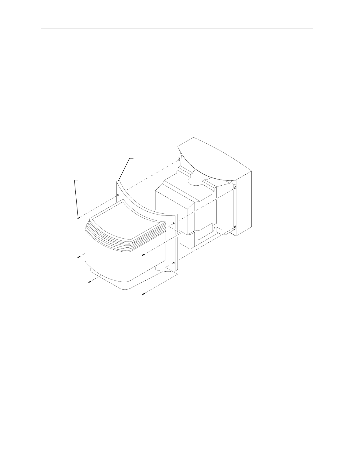
6. Remove the swivel base from the monitor by sliding it to the back of the monitor.
Page 15

7. Place the adapter bracket (MMSA408) onto the bottom of monitor. Ensure the holding latches
are secured inside the slots in the monitor frame.
Adapter
Bracket
11
Slot
8. Slide the bracket toward the front of the monitor to secure it in place. The bracket sn aps in
without using screws.
9. Re-attach the monitor cover to the monitor and secure it with the screws removed in step 3.
Page 16

12
10. Attach the filler bracket (MMSA409) to the bottom of the adapter bracket. Use the four
M5x8mm (CPHM035) screws.
Filler
Bracket
Replacing the Monitor Collar
The collar shipped on the ErgoView stand is designed for CLIX workstation monitors only. You
must replace this collar with the one in the mounting kit before installing the Panasonic OEM
monitor.
1. Remove the tilt adjustment knob, located where the monitor collar attaches to the ErgoView
stand.
2. Remove the hinge pin cover and discard it. The hinge pin cover is attached with double-sided
tape.
3. Using retaining ring pliers, remove a retaining ring and the hinge pin from the collar.
4. Remove the collar from the stand.
5. Set the new collar into the stand.
6. Attach the hinge pin and retaining ring.
7. Replace the tilt adjustment knob.
Page 17

8. Using four six-inch pieces of the one-inch wide adhesive tape (CPTP076), attach the cover plate
(CFAB325) to the underside of the aluminum plate.
Collar
Aluminmun
Plate
13
Tape
Cover Plate
Installing the Monitor
CAUTION Ensure the new collar is completely secure in the stand before installing the OEM monitor.
1. Lock the tilt adjustment knob.
2. Set the monitor in the collar. The filler bracket sits on the aluminum plate, attached to the
bottom of the collar.
WARNING Ensure that one person holds the top of the monitor to prevent it from tipping downward when
initially placed in the monitor collar.
3. Thread the four M5x16mm screws (CPHM041) through the bottom of the cover plate (outer
holes) into the filler bracket. Tighten the screws.
Page 18

14
4. Attach the blanking plate to the collar above the monitor. Use the washers (CPHM129) and nuts
(CPHM048) to secure the plate to the collar.
Blanking
Plate
Filler
Bracket
See “Connecting the Cables” to finish setting up the ErgoView stand.
Page 19
5 Connecting the Cables
This section includes procedures for connecting cables from the ErgoView stand to the digitizing
table supported by either an Intergraph Computer Systems or Hamilton table base. Verify that the
following items have been supplied:
u
Interconnect jumper (MCBLT29)
u
AC power cord (CWIR378)
u
Hand-held control cable (MCBLW020)
u
Cable kit with standalone safety jumper (MCBLF39) and AC adapter cable (MCBLT73)
For dual ErgoView stands, these additional items should be supplied:
u
Logic interconnect cable (CLBLT28)
u
AC power interconnect cable (CWIR389)
u
Hand-held control cable (MCBLW020)
Single ErgoView Stand
15
WARNING Never connect a digitizing table base to an AC power wall outlet when used with the ErgoView
stand. The digitizing table base must be connected to the ErgoView stand for safe operation.
This will ensure power shutdown to the table base in case of an obstruction.
1. For an Intergraph Computer Systems base, insert the standalone safety jumper (MCBLT29) into
the table base as shown in the following figure. Then insert one end of the power cord
(CWIR378) into the AC receptacle in the table base.
Safety
Jumper
AC
Receptacle
Page 20

16
For a Hamilton base, connect the AC adapter cable (MCBLT73) to the existing Hamilton base
power cord.
NOTE The base power cord is permanently attached to the Hamilton base.
Base
AC Adapter
Cable
Power
Cord
2. Remove the AC receptacle cover from the ErgoView stand as shown in the following figure.
Connect the power cord (or AC adapter cable) to the AC receptacle.
3. If installing a single ErgoView stand, attach the interconnect jumper into the standalone safety
jumper. Do not install the interconnect jumper for dual stands.
AC Receptacle
Cover
Interconnect
Jumper
Power Cord
(or AC Adapter
Cable)
To table
base
CAUTION When connecting cables from a digitizing table base to the ErgoView stand, always use the AC
receptacle on the front of the ErgoView stand. This will ensure power shutdown to the table base in
case of an obstruction.
Page 21

4. Connect one end of the AC power cord (CWIR378) to the top AC receptacle on the back of the
ErgoView stand. Connect the other end of the AC power cable to an unobstructed AC power
wall outlet.
AC Power
Cord
Receptacle
Covers
WARNING To prevent current overloading, the number of external connections must be limited. Do not
remove receptacle covers on the back of the ErgoView stand unless required.
17
Note The bottom receptacle labeled 120V, 1A, is for the FTIS044 digitizer controller, if used. For dual
configurations, use either middle or bottom AC receptacle to connect the digitizer controller. The
appropriate power cord will be supplied with the controller.
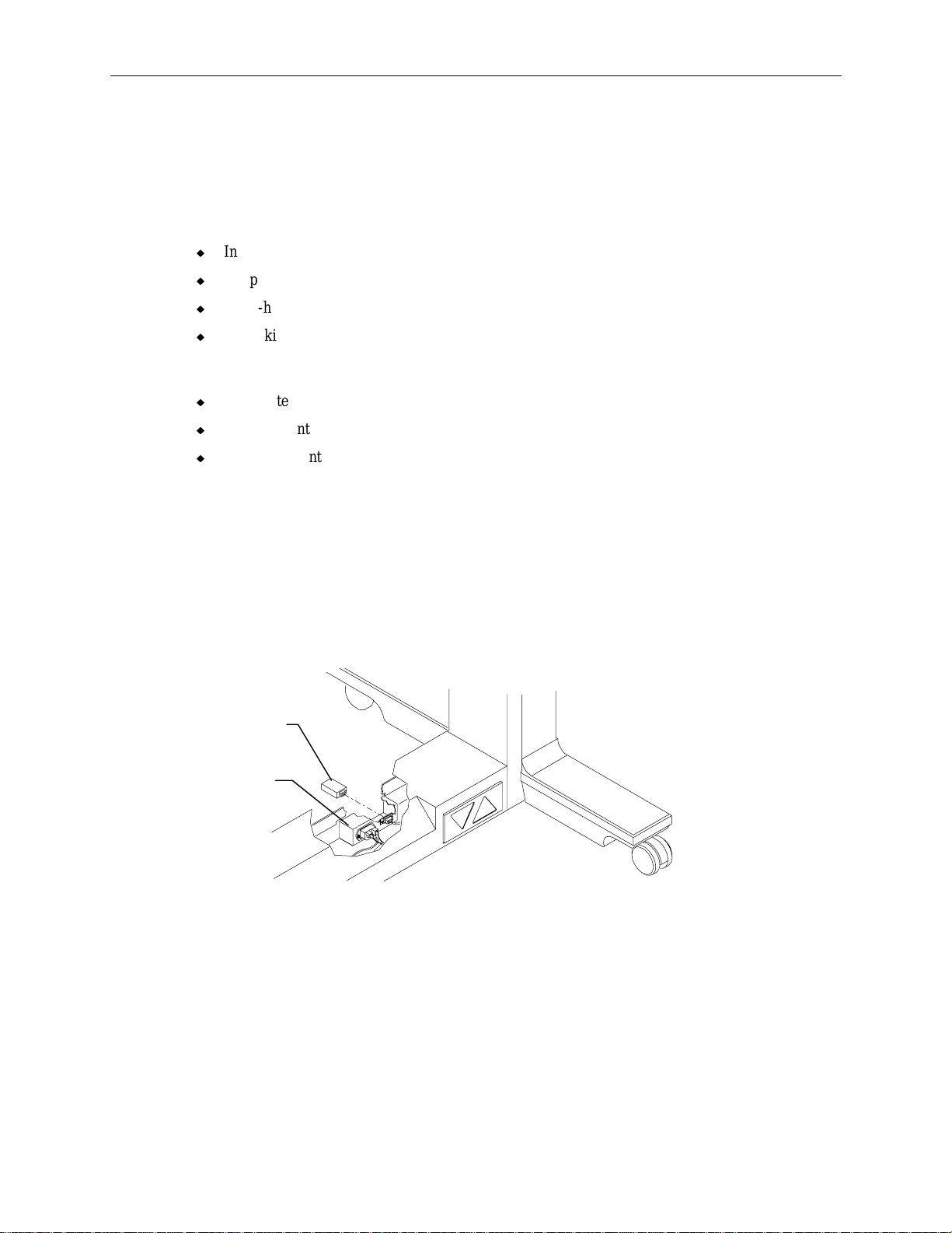
5. Plug the hand-held controller cable (P1 end) into modular jack J2 at the upper-right side of the
back of the ErgoView stand.
Modular Jack J 2
LED
6. Raise the pedestal up to its maximum height by pressing the hand-held controller switch.
7. Loosen the tilt knob until the monitor moves freely. Tilt the monitor down to the position desired
by an operator.
8. Tighten the tilt adjustment knob.
Note If the tilt angle of the monitor is adjusted, or the monitor encounters an obstruction, a strain gauge
senses a change in the weight of the monitor. The LED at the back of the stand illuminates and power
is removed from the table base. At this point, the stand cannot be lowered until the circuitry is reset.
To reset the circuitry, press the hand-held control cable switch to first raise the stand. Remove the
obstruction if present; then lower the ErgoView stand.
Page 22

18
See the system’s hardware documentation to connect other cables and to start the system. See “Dual
ErgoView Stands” if you are connecting the cables for a second ErgoView stand.
Dual ErgoView Stands
After you connect the cables for the first ErgoView stand as described in “Single ErgoView Stand,”
perform the following steps to connect the cables for a second ErgoView stand.
1. Connect the logic interconnect cable between the 4-pin DIN plug on the front of both ErgoView
stands.
Logic Interconnect
Cable
Second Stand
First Stand
2. Remove the cover from the receptacle labeled 120V, 5A, on the back of the first ErgoView stand.
Connect the AC power interconnect cable to the 120V, 5A receptacle.
AC Power
Interconnect
Cable
120V, 5A
Receptacle
Page 23

19
3. Connect the other end of the AC power interconnect cable to the top AC receptacle on the back of
the second ErgoView stand.
AC Power
Interconnect Cable
AC
Receptacle
4. Plug the hand-held controller cable (P1 end) into modular jack J2 at the upper-right side of the
back of the ErgoView stand.
Modular Jack J2
LED
5. Raise the pedestal up to its maximum height by pressing the hand-held controller switch.
6. Loosen the tilt knob until the monitor moves freely. Tilt the monitor down to the position desired
by an operator.
7. Tighten the tilt adjustment knob.
Note If the tilt angle of the monitor is adjusted, or the monitor encounters an obstruction, a strain gauge
senses a change in the weight of the monitor. The LED at the back of the stand illuminates and power
is removed from the table base. At this point, the stand cannot be lowered until the circuitry is reset.
To reset the circuitry, press the hand-held control cable switch to first raise the stand. Remove the
obstruction if present; then lower the ErgoView stand.
See the system’s hardware documentation to connect other cables and to start the system.
Page 24

20
6 Replacing a CLIX Workstation Monitor
Follow these instructions to replace a CLIX workstation monitor with an OEM monitor in an existing
ErgoView workstation. Read all of the instructions completely before beginning the replacement.
WARNING The monitors used in ErgoView workstations are heavy and could cause serious personal
injury if dropped. Two persons should lift and carry the monitor.
1. Disconnect the power cord from the CLIX workstation monitor and the AC power outlet.
2. Using a No. 2 Phillips screwdriver, remove and retain the screws that secure the CLIX
workstation monitor to the ErgoView stand. The screws are located underneath the monitor.
3. Remove the monitor and set it aside.
WARNING Do not set the monitor on its display screen. Damage may result.
4. Install the OEM monitor as described in “Hitachi OEM Monitor” or “Panasonic OEM Monitor.”
 Loading...