

Page 1
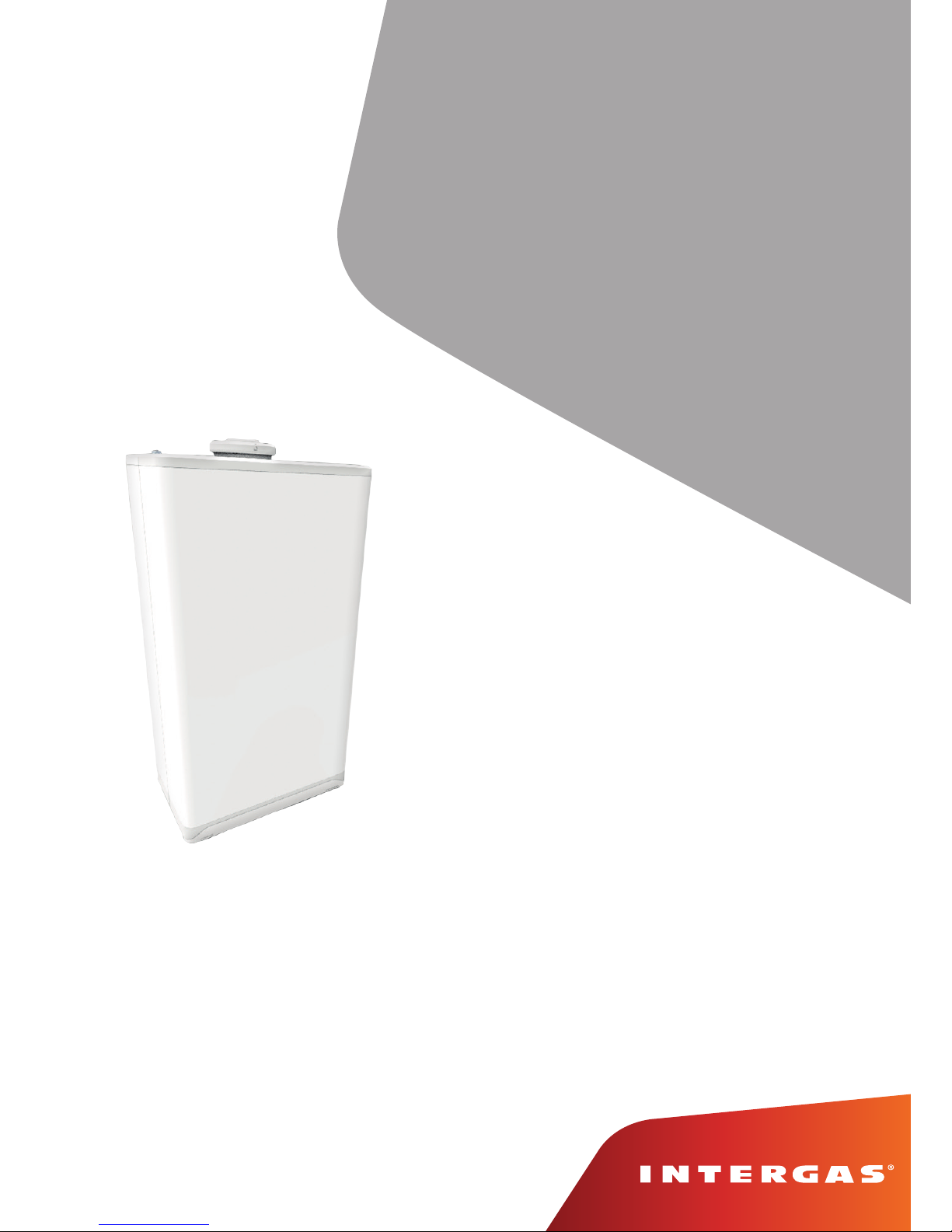
INSTALLATION MANUAL
High Eiciency Wall-Mounted Gas Boiler
Read this installation manual thoroughly before the installation and use of the
boiler. Follow all indicated instructions. This installation manual must remain
with the boiler.
XTREME 24
XTREME 30
XTREME 36
G.C. 47-291-10
G.C. 47-291-11
G.C. 47-291-12
Page 2

2
1 Preface 5
1.1 Regulation ....................................................................................................................5
1.2 Warnings .....................................................................................................................5
1.3 Manual handling ..............................................................................................................5
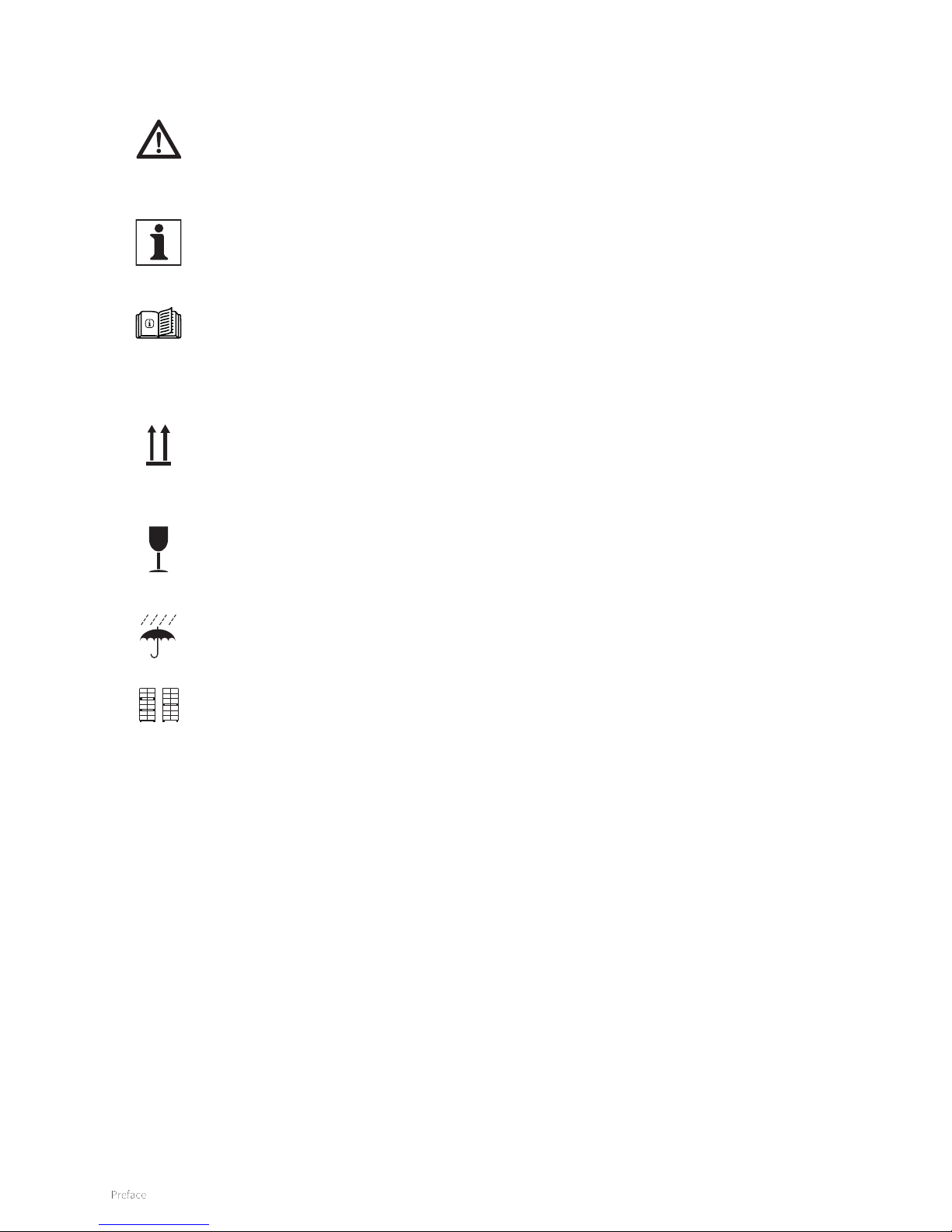
1.4 Pictograms ...................................................................................................................6
1.5 Warnings on the box ...........................................................................................................6
1.6 Abbreviations .................................................................................................................6
2 Safety regulations 7
2.1 General .......................................................................................................................7
2.2 The installation ...............................................................................................................7
3 General boiler information 8
3.1 General .......................................................................................................................8
3.1.1 ErP label . . . . . . . . . . . . . . . . . . . . . . . . . . . . . . . . . . . . . . . . . . . . . . . . . . . . . . . . . . . . . . . . . . . . . . . . . . . . . . . . . . . . . . . . . . . . . . . . . . . . . . . . . . . . . . . . . . . . . . 8
3.1.2 Gas category . . . . . . . . . . . . . . . . . . . . . . . . . . . . . . . . . . . . . . . . . . . . . . . . . . . . . . . . . . . . . . . . . . . . . . . . . . . . . . . . . . . . . . . . . . . . . . . . . . . . . . . . . . . . . . . . . . 8
3.3 Data plate ....................................................................................................................9
3.2 Operation ....................................................................................................................9
3.4 Control panel ................................................................................................................10
3.5 Operational modes ...........................................................................................................10
4 Main components 11
4.1 Standard scope of delivery ....................................................................................................12
4.2 Accessories ..................................................................................................................13
4 Installer important points 14
5 Installation 15
5.1 Overall dimensions of boiler + assembly bracket ...............................................................................15
5.1.1 Installing the wall bracket and assembly bracket . . . . . . . . . . . . . . . . . . . . . . . . . . . . . . . . . . . . . . . . . . . . . . . . . . . . . . . . . . . . . . . . . . . . . . . . . . . . . . .15
5.2 Installation location ..........................................................................................................16
5.2.1 Installation in a kitchen cabinet . . . . . . . . . . . . . . . . . . . . . . . . . . . . . . . . . . . . . . . . . . . . . . . . . . . . . . . . . . . . . . . . . . . . . . . . . . . . . . . . . . . . . . . . . . . . . . . 16
5.2.2 Removing/installing the front panel . . . . . . . . . . . . . . . . . . . . . . . . . . . . . . . . . . . . . . . . . . . . . . . . . . . . . . . . . . . . . . . . . . . . . . . . . . . . . . . . . . . . . . . . . . . 17
5.3 Installing the boiler ...........................................................................................................18
6 Connection 19
6.1 Connecting the central heating system ........................................................................................19
6.1.1 Expansion vessel . . . . . . . . . . . . . . . . . . . . . . . . . . . . . . . . . . . . . . . . . . . . . . . . . . . . . . . . . . . . . . . . . . . . . . . . . . . . . . . . . . . . . . . . . . . . . . . . . . . . . . . . . . . . .19
6.1.2 Thermostatic radiator valves . . . . . . . . . . . . . . . . . . . . . . . . . . . . . . . . . . . . . . . . . . . . . . . . . . . . . . . . . . . . . . . . . . . . . . . . . . . . . . . . . . . . . . . . . . . . . . . . . . 19
6.1.3 Floor heating . . . . . . . . . . . . . . . . . . . . . . . . . . . . . . . . . . . . . . . . . . . . . . . . . . . . . . . . . . . . . . . . . . . . . . . . . . . . . . . . . . . . . . . . . . . . . . . . . . . . . . . . . . . . . . . .19
6.1.4 LT/HT zone system . . . . . . . . . . . . . . . . . . . . . . . . . . . . . . . . . . . . . . . . . . . . . . . . . . . . . . . . . . . . . . . . . . . . . . . . . . . . . . . . . . . . . . . . . . . . . . . . . . . . . . . . . . .20
6.1.5 Division of central heating system in groups with extra heat source 21
CONTENTS
Benchmark places responsibilities on both manufacturers and installers. The purpose is to ensure that customers are provided
with the correct equipment for their needs, that it is installed, commissioned and serviced in accordance with the manufacturer’s
instructions by competent persons and that it meets the requirements of the appropriate Building Regulations. The Benchmark
Checklist can be used to demonstrate compliance with Building Regulations and should be provided to the customer for future
reference. Please read the Benchmark Checklist carefully, page , and complete all sections, as required by law, relevant to the
appliance and installation. Failure to install and commission according to the manufacturer’s instructions and complete the
Benchmark Commissioning Checklist will invalidate the warranty for the Gas Boiler installation. The details within the Checklist
will be required in the event of any warranty work. On completion the Checklist must be le with the end user. The relevant
sections of the Service Record, page , must be completed on each subsequent Service visit.
Installers are required to carry out installation, commissioning and servicing work in accordance with the Benchmark Code of
Practice which is available from the Heating and Hotwater Industry Council who manage and promote the scheme. Visit www.
centralheating.co.uk for more information.
Page 3

3
6.2 Connection of domestic hot water ............................................................................................22
6.2.1 DHW circuit resistance graph . . . . . . . . . . . . . . . . . . . . . . . . . . . . . . . . . . . . . . . . . . . . . . . . . . . . . . . . . . . . . . . . . . . . . . . . . . . . . . . . . . . . . . . . . . . . . . . . . .22
6.2.2 Boiler with heat pump boiler . . . . . . . . . . . . . . . . . . . . . . . . . . . . . . . . . . . . . . . . . . . . . . . . . . . . . . . . . . . . . . . . . . . . . . . . . . . . . . . . . . . . . . . . . . . . . . . . . .23
6.2.3 Boiler with Pre-Heated Solar Boiler) . . . . . . . . . . . . . . . . . . . . . . . . . . . . . . . . . . . . . . . . . . . . . . . . . . . . . . . . . . . . . . . . . . . . . . . . . . . . . . . . . . . . . . . . . . .24
6.3 Electrical connection .........................................................................................................25
6.4 Gas connection ..............................................................................................................25
6.5 Connecting room thermostat .................................................................................................26
6.5.1 Connecting Modulating OpenTherm thermostat . . . . . . . . . . . . . . . . . . . . . . . . . . . . . . . . . . . . . . . . . . . . . . . . . . . . . . . . . . . . . . . . . . . . . . . . . . . . . . .26
6.5.2 Connecting on/o room thermostat . . . . . . . . . . . . . . . . . . . . . . . . . . . . . . . . . . . . . . . . . . . . . . . . . . . . . . . . . . . . . . . . . . . . . . . . . . . . . . . . . . . . . . . . . . .26
6.5.3 Connecting 230V room thermostat . . . . . . . . . . . . . . . . . . . . . . . . . . . . . . . . . . . . . . . . . . . . . . . . . . . . . . . . . . . . . . . . . . . . . . . . . . . . . . . . . . . . . . . . . . . .26
6.5.4 Connecting outdoor sensor . . . . . . . . . . . . . . . . . . . . . . . . . . . . . . . . . . . . . . . . . . . . . . . . . . . . . . . . . . . . . . . . . . . . . . . . . . . . . . . . . . . . . . . . . . . . . . . . . . .27
6.5.5 Frost protection . . . . . . . . . . . . . . . . . . . . . . . . . . . . . . . . . . . . . . . . . . . . . . . . . . . . . . . . . . . . . . . . . . . . . . . . . . . . . . . . . . . . . . . . . . . . . . . . . . . . . . . . . . . . . . 27
6.5.6 Connecting boiler sensor/thermostat . . . . . . . . . . . . . . . . . . . . . . . . . . . . . . . . . . . . . . . . . . . . . . . . . . . . . . . . . . . . . . . . . . . . . . . . . . . . . . . . . . . . . . . . . .28
6.5.7 PC interface . . . . . . . . . . . . . . . . . . . . . . . . . . . . . . . . . . . . . . . . . . . . . . . . . . . . . . . . . . . . . . . . . . . . . . . . . . . . . . . . . . . . . . . . . . . . . . . . . . . . . . . . . . . . . . . . . 28
6.5.8 Comfort Touch . . . . . . . . . . . . . . . . . . . . . . . . . . . . . . . . . . . . . . . . . . . . . . . . . . . . . . . . . . . . . . . . . . . . . . . . . . . . . . . . . . . . . . . . . . . . . . . . . . . . . . . . . . . . . .28
6.6 Flue and air supply duct ......................................................................................................29
6.6.1 Dra, materials and insulation . . . . . . . . . . . . . . . . . . . . . . . . . . . . . . . . . . . . . . . . . . . . . . . . . . . . . . . . . . . . . . . . . . . . . . . . . . . . . . . . . . . . . . . . . . . . . . . .29
6.7 Pipeline lengths ..............................................................................................................30
6.7.1 Replacement lengths . . . . . . . . . . . . . . . . . . . . . . . . . . . . . . . . . . . . . . . . . . . . . . . . . . . . . . . . . . . . . . . . . . . . . . . . . . . . . . . . . . . . . . . . . . . . . . . . . . . . . . . . .30
6.7.2 Example calculation . . . . . . . . . . . . . . . . . . . . . . . . . . . . . . . . . . . . . . . . . . . . . . . . . . . . . . . . . . . . . . . . . . . . . . . . . . . . . . . . . . . . . . . . . . . . . . . . . . . . . . . . . . 30
6.8 General layout of the flue .....................................................................................................31
6.8.1 Wall terminal with twin-pipe horizontal terminal C13 . . . . . . . . . . . . . . . . . . . . . . . . . . . . . . . . . . . . . . . . . . . . . . . . . . . . . . . . . . . . . . . . . . . . . . . . . . .32
6.8.2 Façade combi-pipe horizontal terminal C13 . . . . . . . . . . . . . . . . . . . . . . . . . . . . . . . . . . . . . . . . . . . . . . . . . . . . . . . . . . . . . . . . . . . . . . . . . . . . . . . . . . . .33
6.8.3 Roof terminal with combi-pipe vertical terminal and twin-pipe vertical terminal C33 34
6.8.4 Roof terminal and air supply duct from the façade C53 . . . . . . . . . . . . . . . . . . . . . . . . . . . . . . . . . . . . . . . . . . . . . . . . . . . . . . . . . . . . . . . . . . . . . . . . .35
6.8.5 Clamping the flue system (parallel and concentric) . . . . . . . . . . . . . . . . . . . . . . . . . . . . . . . . . . . . . . . . . . . . . . . . . . . . . . . . . . . . . . . . . . . . . . . . . . . . .36
7 Operation 38
7.1 Using the control panel .......................................................................................................38
7.2 Preparation activities .........................................................................................................38
7.2.1 Filling and venting central heating system . . . . . . . . . . . . . . . . . . . . . . . . . . . . . . . . . . . . . . . . . . . . . . . . . . . . . . . . . . . . . . . . . . . . . . . . . . . . . . . . . . . . .38
7.2.2 Domestic hot tap water facility . . . . . . . . . . . . . . . . . . . . . . . . . . . . . . . . . . . . . . . . . . . . . . . . . . . . . . . . . . . . . . . . . . . . . . . . . . . . . . . . . . . . . . . . . . . . . . . .39
7.2.3 Gas supply . . . . . . . . . . . . . . . . . . . . . . . . . . . . . . . . . . . . . . . . . . . . . . . . . . . . . . . . . . . . . . . . . . . . . . . . . . . . . . . . . . . . . . . . . . . . . . . . . . . . . . . . . . . . . . . . . . . 39
7.3 Commissioning procedure ....................................................................................................40
7.4 Clock function ...............................................................................................................41
7.5 Shutting down the boiler .....................................................................................................42
8 Settings and adjustments 43
8.1 Structure of the settings ......................................................................................................43
8.1.1 Main menu . . . . . . . . . . . . . . . . . . . . . . . . . . . . . . . . . . . . . . . . . . . . . . . . . . . . . . . . . . . . . . . . . . . . . . . . . . . . . . . . . . . . . . . . . . . . . . . . . . . . . . . . . . . . . . . . . .43
8.1.2 Domestic hot water menu . . . . . . . . . . . . . . . . . . . . . . . . . . . . . . . . . . . . . . . . . . . . . . . . . . . . . . . . . . . . . . . . . . . . . . . . . . . . . . . . . . . . . . . . . . . . . . . . . . . .44
8.1.3 Central heating menu . . . . . . . . . . . . . . . . . . . . . . . . . . . . . . . . . . . . . . . . . . . . . . . . . . . . . . . . . . . . . . . . . . . . . . . . . . . . . . . . . . . . . . . . . . . . . . . . . . . . . . . .45
8.1.4 RF menu . . . . . . . . . . . . . . . . . . . . . . . . . . . . . . . . . . . . . . . . . . . . . . . . . . . . . . . . . . . . . . . . . . . . . . . . . . . . . . . . . . . . . . . . . . . . . . . . . . . . . . . . . . . . . . . . . . . . . 45
8.1.5 Service menu . . . . . . . . . . . . . . . . . . . . . . . . . . . . . . . . . . . . . . . . . . . . . . . . . . . . . . . . . . . . . . . . . . . . . . . . . . . . . . . . . . . . . . . . . . . . . . . . . . . . . . . . . . . . . . . . 47
8.2 Setting and adjusting the clock functions ......................................................................................49
8.2.1 Setting the clock program on CH operation . . . . . . . . . . . . . . . . . . . . . . . . . . . . . . . . . . . . . . . . . . . . . . . . . . . . . . . . . . . . . . . . . . . . . . . . . . . . . . . . . . . .49
8.2.2 Setting the clock program on DHW operation . . . . . . . . . . . . . . . . . . . . . . . . . . . . . . . . . . . . . . . . . . . . . . . . . . . . . . . . . . . . . . . . . . . . . . . . . . . . . . . . . . 50
8.3 Parameters ..................................................................................................................52
8.4 Switching DHW comfort function on and o. . . . . . . . . . . . . . . . . . . . . . . . . . . . . . . . . . . . . . . . . . . . . . . . . . . . . . . . . . . . . . . . . . . . . . . . . . . . . . . . . . . .53
8.5 Adjusting maximum central heating output ....................................................................................53
8.6 Adjusting pump capacity .....................................................................................................53
8.7 Weather-dependent control ..................................................................................................54
8.8 Conversion to another gas type ...............................................................................................55
8.9 Gas/air control ...............................................................................................................56
8.10 Inspection of gas air control ...................................................................................................57
8.10.1 Measuring flue gas at maximum output . . . . . . . . . . . . . . . . . . . . . . . . . . . . . . . . . . . . . . . . . . . . . . . . . . . . . . . . . . . . . . . . . . . . . . . . . . . . . . . . . . . . . . . . 57
8.10.2 Measuring flue gas at minimum output . . . . . . . . . . . . . . . . . . . . . . . . . . . . . . . . . . . . . . . . . . . . . . . . . . . . . . . . . . . . . . . . . . . . . . . . . . . . . . . . . . . . . . . .59
8.10.3 Minimum output correction . . . . . . . . . . . . . . . . . . . . . . . . . . . . . . . . . . . . . . . . . . . . . . . . . . . . . . . . . . . . . . . . . . . . . . . . . . . . . . . . . . . . . . . . . . . . . . . . . . .61
9 Faults 63
9.1 Fault codes ..................................................................................................................63
9.2 Other faults ..................................................................................................................65
9.2.1 No heat (central heating) . . . . . . . . . . . . . . . . . . . . . . . . . . . . . . . . . . . . . . . . . . . . . . . . . . . . . . . . . . . . . . . . . . . . . . . . . . . . . . . . . . . . . . . . . . . . . . . . . . . . .65
9.2.2 Central heating does not reach the correct temperature . . . . . . . . . . . . . . . . . . . . . . . . . . . . . . . . . . . . . . . . . . . . . . . . . . . . . . . . . . . . . . . . . . . . . . . . 65
9.2.3 Central heating system remains too warm . . . . . . . . . . . . . . . . . . . . . . . . . . . . . . . . . . . . . . . . . . . . . . . . . . . . . . . . . . . . . . . . . . . . . . . . . . . . . . . . . . . . . 65
9.2.4 No domestic hot water (DHW) . . . . . . . . . . . . . . . . . . . . . . . . . . . . . . . . . . . . . . . . . . . . . . . . . . . . . . . . . . . . . . . . . . . . . . . . . . . . . . . . . . . . . . . . . . . . . . . . .66
9.2.5 Domestic hot tap water does not reach the correct temperature 66
9.2.6 Burner ignites loudly . . . . . . . . . . . . . . . . . . . . . . . . . . . . . . . . . . . . . . . . . . . . . . . . . . . . . . . . . . . . . . . . . . . . . . . . . . . . . . . . . . . . . . . . . . . . . . . . . . . . . . . . .66
9.2.7 Burner resonates . . . . . . . . . . . . . . . . . . . . . . . . . . . . . . . . . . . . . . . . . . . . . . . . . . . . . . . . . . . . . . . . . . . . . . . . . . . . . . . . . . . . . . . . . . . . . . . . . . . . . . . . . . . . . 67
Page 4

4
10 Maintenance 68
10.1 Disassembly .................................................................................................................68
10.2 Cleaning .....................................................................................................................68
10.3 Installation ..................................................................................................................69
10.4 Checklist ....................................................................................................................70
11 Technical specifications 71
11.1 Electrical schematic ..........................................................................................................72
11.2 Product card according to CELEX-32013R0811, Appendix IV .....................................................................74
11.3 NTC resistances ..............................................................................................................74
12 Guarantee provisions and CE declaration 75
13 Gas boiler system commissioning checklist 76
14 Service record 77
To be completed at each annual service, not subsequent.
To be completed at each annual service, not subsequent.
Page 5

5
1 PREFACE
The manufacturer Intergas Heating Ltd accepts no liability
whatsoever for damage or injury caused by failure to adhere
(strictly) to the safety regulations and instructions, or
carelessness during installation of the Intergas Boiler wall
mounted gas fired boiler and any associated accessories
Intergas Heating Ltd continuously developing ways to
guarantee the quality of its products and to improve them
where necessary. In so doing it reserves the right to modify at
any time the features named in this document.
Read and observe all safety instructions in this instruction
manual to prevent unsafe situations, fire, explosion, damage to
property or personal injury.
1.1 Regulation
1.2 Warnings
1.3 Manual handling
The Intergas combination boiler meets the requirements of Statutory Instrument 'The
Boiler (Eiciency) Regulations' and is deemed to meet the requirements of:
► Low Voltage Directive (2014/35/EC)
► Gas Appliances Regulation (2016/426/EC)
► Boiler Eiciency Directive for new oil- and gas-fired central heating boilers (92/42/EC)
► EMC Directive (2014/30/EC)
► RED Directive (2014/53/EU)
► Ecodesign (2009/125/EG)
► Energy labelling 2010/30/EU
Intergas declares that the materials used in the manufacturing of this appliance are
nonhazardous and that no substances harmful to health are contained within the
appliance.
Intergas accepts no responsibility for the unsatisfactory
performance of the appliance or flue arising from the failure
to comply with the installation and user instructions. Incorrect
installation could invalidate your guarantee and may lead to
prosecution.
The appliance cannot be removed from the orginal place of
installation and transferred to another site or re-sold without prior
consent from Intergas to re-register the appliance with Intergas in
order to maintain the warranty.
The boiler must be installed in accordance with these instructions
and the regulations currently in force. Read these instructions
carefully before installing or using the appliance. It is the installers
responsibility that the installation conforms to the current
legislation and Standard Codes of Practice.
When moving the boiler always keep your back straight, bend
your knees, don’t twist, move your feet. Avoid bending forwards or
sideways and keep the load as close to your body as
possible. Where possible transport the boiler using a suitable
trolley, sack truck or get some assistance. Grip the boiler firmly and
before liing establish where the weight is concentrated to
determine the centre of gravity, repositioning yourself if necessary.
Page 6
6
1.6 Abbreviations
► DHW: Domestic hot water
► CH: Central heating
► CW: Comfort domestic hot water
► HE: High eiciency
► PHS: Pre Heated Solar water.
► LT: Low temperature (zone).
► HT: High temperature (zone)
► OT: OpenTherm
► RF: Radio frequency
► PC: Personal computer
► NTC: Sensor (Negative temperature coeicient)
► PP: Polypropylene
► CAC: Combination air supply duct and combustible
gas flue system (chimney system)
1.4 Pictograms
CAREFUL / IMPORTANT
Procedures which, if these are not performed
with the required caution, can damage the
product, the surrounding or the environment or
may result in personal injury.
COMMENT
Procedures and/or instructions which, if they
are not followed, can negatively aect the
operation of the boiler.
The following pictograms are used in this installation manual:
1.5 Warnings on the box
SEE
Reference to other manuals
INSTRUCTION (THIS SIDE UP)
Store the appliance upright as indicated on the
box.
INSTRUCTION (FRAGILE)
This is a fragile piece of equipment: Please be
very careful not to drop.
MAX 3 MAX2
INSTRUCTION (FRAGILE)
This is a fragile piece of equipment: Please
provide a dry storage for the appliance.
INSTRUCTIE (STACK)
No more than three boxes should be stacked on
top of each other.
Page 7

7
A gas leak could potentially cause an
explosion. If you smell gas, observe the
following rules:
► Prevent flames or sparks:
- Do not smoke, use a lighter or strike
matches.
- Do not operate any electrical switches
or unplug any equipment.
- Do not use the telephone or ring
doorbells.
► Turn o the gas at the meter or regulator.
► Open windows and doors.
► Warn your neighbors and leave the
building
► Prevent anyone from entering the
building.
► Call the National Gas Emergency Service
on 0800 111 999.
L.P.G. boilers: Call the supplier’s number
on the side of the gas tank
It is law that all gas appliances are installed and serviced by a Gas Safe registered
competent engineer if in any doubt please check with Gas Safe (0800 408 5500)
and in accordance with the following recommendations:
► Current Gas Safety (Installation and Use) Regulations
► All current building regulations
► Building Standards (Scotland) Consolidated
► This appliance must be installed in accordance with the Gas (Safety and Use)
Regulations, current Building Regulations, Building Standards (Scotland),
I.S.813 Installation of Gas Appliances (Ireland), IEE Wiring Regulations (BS
7671), Health and Safety Document No. 635 (Electricity at Work Regulations)
and Local Water Authority Bye Laws
► UK Water Regulations and Bye Laws
► Health & Safety
2.1 General
2.2 The installation
The installation must comply with the following British Standards codes of practice:
► BS 5440: Flues and Ventilation for gas appliances of rated input not exceeding 70kW
(Part 1 Flues)
► BS 5440: Flues and Ventilation for gas appliances of rated input not exceeding 70kW
(Part 2 Air Supply)
► BS 5546: 2000 Installation of gas hot water supplies for domestic purposes.
► BS 5549: 1990 Forced circulation hot water systems
► BS 6700: 1997 Design, Installation, testing and maintenance of services supplying hot
water
► BS 6798: 2000 Specification for installation of gas fired hot water boilers of rated input
not exceeding 70kW
► BS 6891: 1998 Installation of low pressure gas pipe-work installations up to 35mm (RI)
► BS 7593: 1992 Code of practice for treatment of water in heating systems
► BS 7671: 2001 Requirements for electrical installations, IEE Wiring regulations
Reference should also be made to:
► Guide to condensing boiler installation assessment procedures for dwellings
► The institute of Gas Engineers document IGE/UP/7 for timber frame dwellings
2 SAFETY REGULATIONS
Safety precautions If you smell gas
Page 8
8
3 GENERAL BOILER INFORMATION
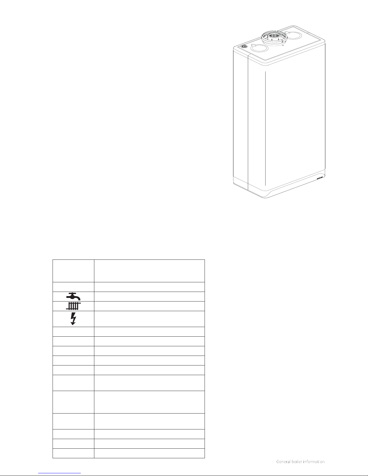
The Intergas Xtreme wall-mounted gas boiler is a closed unit. The boiler is
intended solely to provide heat for the water in a central heating system
and domestic hot water installation for household use.
The Intergas Xtreme meets the European directives and additional national
regulations that are indicated by CE marking. The associated conformity
declaration can be requested from Intergas Heating Ltd (also see §12)
The Intergas Xtreme meets the electrical protection class IPX4D.
The boiler can be connected to stainless steel or plastic (PPT120)
combination throughputs that have a CE label.
3.1 General
3.1.1 ErP label
3.1.2 Gas category
Gas category Gas type Gas inlet pressure
(mbar)
II
2H3P
Natural gas (G20) 20
LPG (G31) 37
The Intergas Xtreme is factory-set for H-gas, G20. The boiler
may optionally be converted to another gas type using a
conversion set (see §8.8).
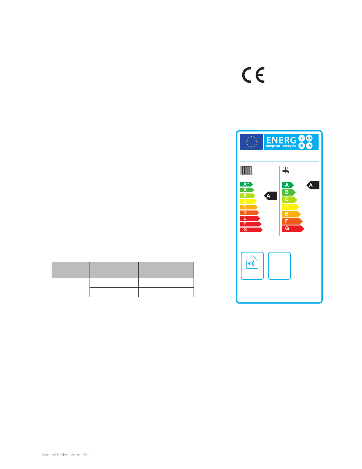
Based on the European ErP Directive (Energy related Products) all newly
produced gas fired boilers have to meet minimum standards regarding
energy performance.
The Intergas Xtreme carries an European energy label containing specific
information regarding energy eiciency class (CH and DHW), noise level
en maximum power.
The Intergas Xtreme carries label A for both CH and DHW.
In addition the Intergas Xtreme meets the following DWH capacity profile:
► Xtreme 24 : L
► Xtreme 30 : XL
► Xtreme 36 : XXL
The extensive product fiche can be found in §11.2.
Xtreme -Intergas Heating Ltd
dB
--
--
kW
2015 811/2013
Page 9
9
Identification of the product
You will find the unit details on the data plate on the bottom
of the unit. The data plate contains, beside the supplier
information and the boiler specification (boiler type and model
name), the following information:
3.3 Data plate
3.2 Operation
The Intergas Xtreme is a modulating high eiciency boiler. This means
that the capacity is adjusted according to the desired heating capacity.
Two separate copper circuits are integrated in the aluminium heat
exchanger.
In addition, the Intergas Xtremehas a second heat exchanger (heat
recovery unit). This second heat exchanger is integrated in the flue of the
boiler so that the eiciency of domestic hot water is increased further.
The residual heat of the flue gases of the central heating use is also used
to preheat the domestic hot water.
By applying this technology, less energy is required to bring the water to
the correct temperature and an extremely high eiciency is achieved.
The boiler has a burner controller which, with each heat demand of the
heater or the domestic hot water facility, controls the pump (only during
heat demand of the heater) and the fan, opens the gas valve, ignites the
burner and continuously monitors and regulates the flame, depending
on the requested capacity.
****
-yymm
****
Production code-Serial no.
YY = year of production,
mm = month of production
PIN
Product Information Number
Data related to Domestic Hot Water
Data related to Central Heating
Information regarding electrical power supply
(Voltage, mains frequency, elmax, IP-class)
PMS
Permissible overpressure in CH circuit in bar
PWS
Permissible overpressure in DHW circuit in bar
Qn HS
Input related to gross caloric value in kilowatts
Qn Hi
Input related to net caloric value in kilowatts
Pn
Output in kilowatts
BE, CH, DE, ES,
FR, GB, IE, IT, MT
Countries of Destination (EN 437)
I2E(s), I2H,
IIELL3P, II2H3P,
II2Esi3P
Approved unit categories (EN 437)
G20-20 mbar
G25-25 mbar
Gas group and gas connection pressure as set
at the factory (EN 437)
B23, ......C93(x)
Approved flue gas category (EN 15502)
Tmax
Maximum flow temperature in °C
IPX4D
Electrical protection class
Page 10

10
The boiler has a number of operational modes:
The boiler is switched o.
The boiler is out of order but is connected to the mains voltage.
In this mode, the display view is characterized by:
► Showing the power LED [ ].
► Showing the pressure in the central heating system (in bar)
on the le display [ ].
► Showing a line on the right display [ ].
The boiler is switched on and is ready for a heat demand.
The boiler is switched on and is ready to answer a request for
either domestic hot water or hot central heating water.
In this mode, the display view is characterized by:
► Showing the power LED [ ]. All other symbols and values
are not displayed.
3.4 Control panel
The boiler has a fully integrated touch screen control panel
that displays information about the operational mode of the
boiler. Symbols (buttons), numbers, points and/or letters are
displayed.
The buttons light up so that they can be operated.
For extensive control options, see §8.
3.5 Operational modes
Boiler is switched o
(mains voltage is present, however)
Boiler is switched on
(ready for heat demand)
The boiler is in operation and is supplying domestic hot
water.
The boiler is in operation and is supplying domestic hot water
to one of the tap points. The display view is characterized by:
► Showing the power LED [ ].
► Showing the flame. The burner is switched on [ ].
► Showing the tap symbol [ ].
The boiler is in operation and is supplying central heating
water.
The boiler is in operation and is supplying central heating
water. The display view is characterized by:
► Showing the power LED [ ].
► Showing the flame. The burner is switched on [ ].
► Showing the radiator symbol [ ].
Boiler is in operation (domestic hot water)
Boiler is in operation (central heating water)
COMMENT
► Only use your fingers to operate the
touch screen
Page 11
11
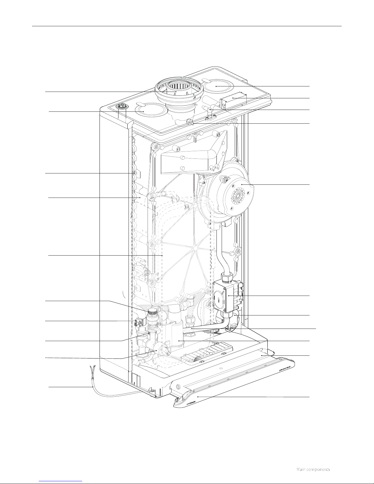
4 MAIN COMPONENTS
Flue adapter
Air supply duct
(not to be removed)
Ignition pin
Ignition unit
Air supply duct
(not to be removed)
Flue sensor
Fan
Gas valve
Pump
Flow sensor
Siphon base
Burner controller
with control panel
Control panel and
readout
Heat exchanger sensor
Heat exchanger
Expansion vessel
shown in broken lines
Domestic hot water sensor
Pressure relief valve
Central heating
flow sensor
Central heating
pressure sensor
Mains lead 230 V
AC without plug
(stripped)
Page 12
12
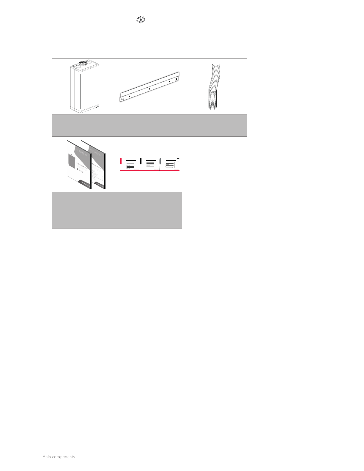
4.1 Standard scope of delivery
Boiler Wall bracket Flexible condensate hose
Garantiebewijs Intergas HR-ketel
Garantiebewijs Intergas HR-ketel Garantiebewijs Intergas HR-ketel
Datum installatie:
Volgens geldende voorschriften
geïnstalleerd door:
Naam installateur:
Adres:
Postcode:
Woonplaats:
Naam koper:
Adres:
Postcode:
Woonplaats:
Het garantiebewijs is slechts geldig, indien de aan het garantiebewijs gehechte
antwoordkaart binnen 8 dagen na de installatie wordt ingezonden. Deze kaart
moet volledig en duidelijk worden ingevuld en voorzien zijn van de handtekening
van koper en installateur. Door ondertekening van deze kaart verklaart koper
zich akkoord met de staat van de ketel bij aflevering.
Het garantiebewijs is slechts geldig, indien de aan het garantiebewijs gehechte
antwoordkaart binnen 8 dagen na de installatie wordt ingezonden. Deze kaart
moet volledig en duidelijk worden
ingevuld en voorzien zijn van de handtekening
van koper en installateur. Door ondertekening van deze kaart verklaart koper
zich akkoord met de staat van de ketel bij aflevering.
Voor de ‘Garantiebepalingen
Intergas HR-ketels’ verwijzen
wij u naar onze website:
www.intergasverwarming.nl
of naar het bij uw HR-ketel
bijgevoegde installatievoorschrift.
Op uw verzoek sturen wij u
graag een exemplaar toe.
Datum installatie:
Naam koper:
Adres:
Postcode:
Woonplaats:
Installateur
>>Betrouwbaar in warmte >>Betrouwbaar in warmte >>Betrouwbaar in warmte
Type/Serienr.
Intergas Verwarming BV
Antwoordnummer 5
7740 VB COEVORDEN
Datum installatie:
Naam koper:
Adres:
Postcode:
Woonplaats:
Type/Serienr. Type/Serienr.
Postzegel
niet nodig
voor klant
voor fabrikant
12345678910
12345678910
12345678910
voor installateur
Installation and operation
instruction
Guarantee card
Check whether the package is undamaged. Unpack the boiler
and check whether all components are present. Also check
for any damages to the boiler or accessories and, if present,
immediately notify the supplier.
Page 13
13
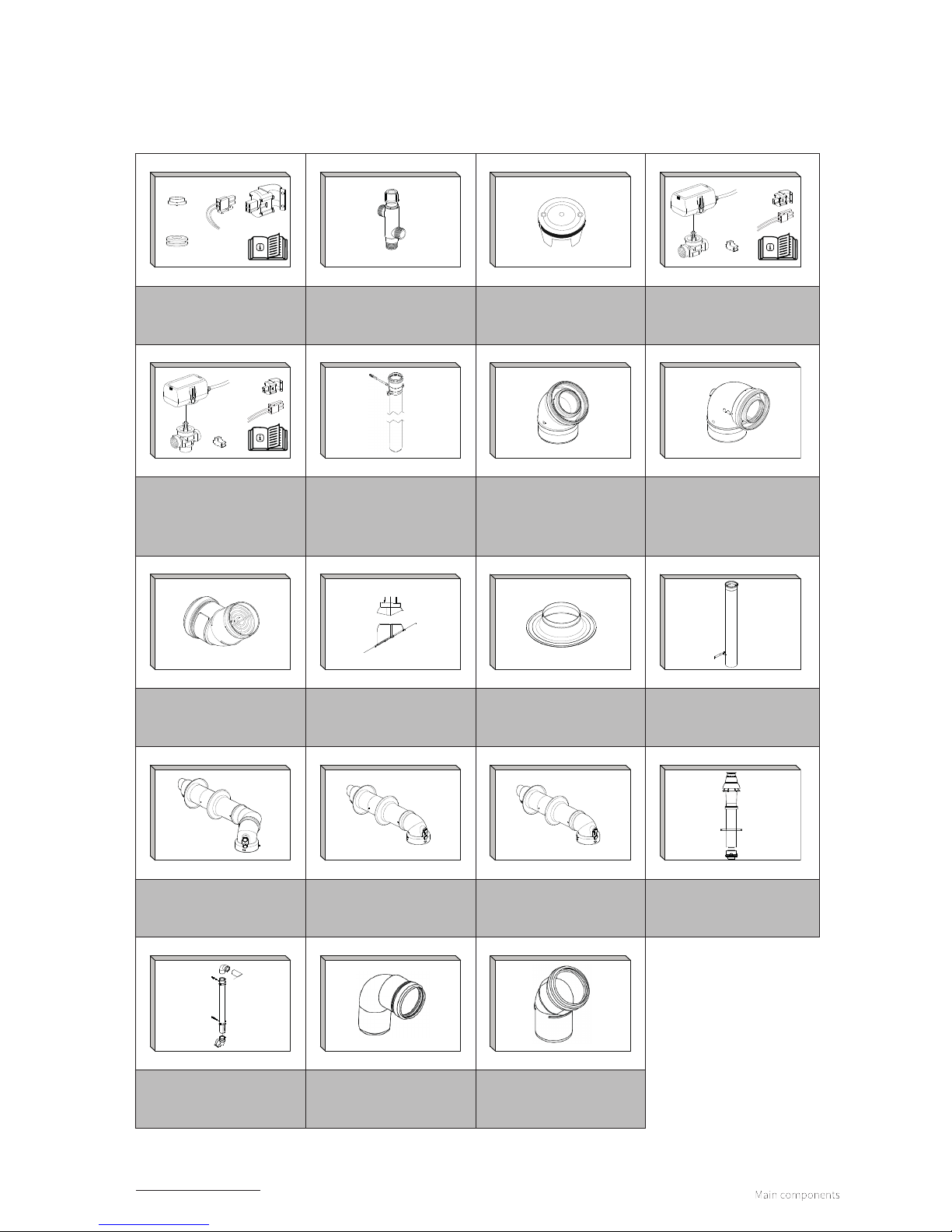
Item no 090347
Post-Heating Solar Boiler
conversion set
Item no 842177
Thermostatic mixing valve
Item no 203207
Outdoor sensor
Item no 093697
LT/HT two-way valve set
Item no 093707
LT/HT three-way valve set
Item no 081286
Extension L=100 incl.
wall bracket (for plume
management kit)
Item no 084661
Bend 45°
Item no 084660
Bend 90°
Item no 081295
Deflector kit
Item no 087910
Weather slate (steep roof)
Item no 087372
Weather slate (flat roof)
Item no 089975
Extension L=100
incl. wall bracket
Item no 081298
Horizontal telescopic
oset wall terminal
1
Item no 082980
Horizontal straight wall
terminal extended
1
Item no 081297
Horizontal telescopic wall
terminal
1
Item no 0821973
Vertical roof terminal
(incl. boiler adapter 60/100)
Item no 081294
Plume management kit
Item no 081284
Elbow 90° (for plume
management kit)
Item no 081285
Elbow 60° (for plume
management kit)
4.2 Accessories
Original Intergas accessories can be ordered separately at
the regular wholesaler. Instructions about the correct way to
assemble and use these accessories are provided upon order
and are therefore not included in this installation manual.
1
Only to be used in combination with the base adapter on the boiler
Page 14

14
4 INSTALLER IMPORTANT POINTS
Please read all instructions before fitting this appliance
► The installer shall instruct the user on the operation of the boiler, safety devices contained within
the boiler and on the location of the filling loop and how to re-pressurise the system if the water
pressure falls.
► The installer should hand over the installation and user instructions upon completion with the
completed Benchmark Commissioning Checklist.
► The service engineer must complete the service record on the Benchmark Checklist aer each
service.
► It is required under Gas Safe Regulations for the installation to be notified to and registered with
Gas Safe, Intergas and Building Control (Gas Safe Notifcation).
► Before proceeding to commission the boiler check the gas inlet pressure is 20mbar (NG) or
37mbar for Propane.
► Combustion analysis with a correctly calibrated and certificated analyser is essential for safe
commissioning of the boiler.
► A pressure reducing valve set to 3.5 bar must be fitted if supply mains pressure is above 4 bar.
► In hard water areas where the PH is 200ppm or above, appropriate protection actions must be
taken in accordance with BS 7593 in line with building regulations Part L.
See also Guarantee Provisions on page 75, point 4.
► The user should be instructed to keep the instructions in a safe place for servicing and future
reference.
► It is important to keep the boiler clear of dust during the installation. In particular, do not allow
debris to enter the flue connection at the top.
► Before fitting the boiler ensure that the pipe work that you are installing is connected to the
appropriate connections on the boiler.
It is important to thoroughly flush the water circuits, aer isolating the boiler, in order to remove
any fluxes and debris from them. This should be done particularly where boilers are being fitted to
existing radiator circuits (please refer to current Standard Codes of Practice).
► Intergas recommend water treatment in accordance with the Benchmark Guidance on Water
Treatment in Central Heating Systems, we recommend the use of FERNOX, SENTINEL or ADEY
inhibitors. It is most important that correct concentration of water treatment is maintained
for the life of the boiler, a water sample is required on installation and to be verified by the
aforementioned manufacturers should we attend a warranty call a water sample may be required
to keep the warranty valid. (BS 7593:2006)
► This boiler has been factory set but adjustment may be required to the heating input in order to
match the individual heating demand. This can be done by changing parameter P010 (= max.
power CH) or parameter P070 (= max. power domestic water).
► Please do not use the pressure relief valve as a means of flushing the system.
► Remember that aer hot water draw of a possible delay may occur before the heating system will
fire up.
► All fluxes, residues and cleaner must be flushed from pipe-work and radiators prior to
commissioning.
► External expansion vessels are best connected water side downwards to allow correct draining/
cleaning of system and to prolong the life of the vessel diaphragm.
► Note: an anti-cycle delay time can be set up to a maximum of 15 minutes by adjusting parameter
P036 as described in §8.3.
► If you experience any problems please refer to the installation and commissioning guidelines
within the boiler instruction manual. If necessary, please contact Intergas Heating Ltd).
Page 15
15
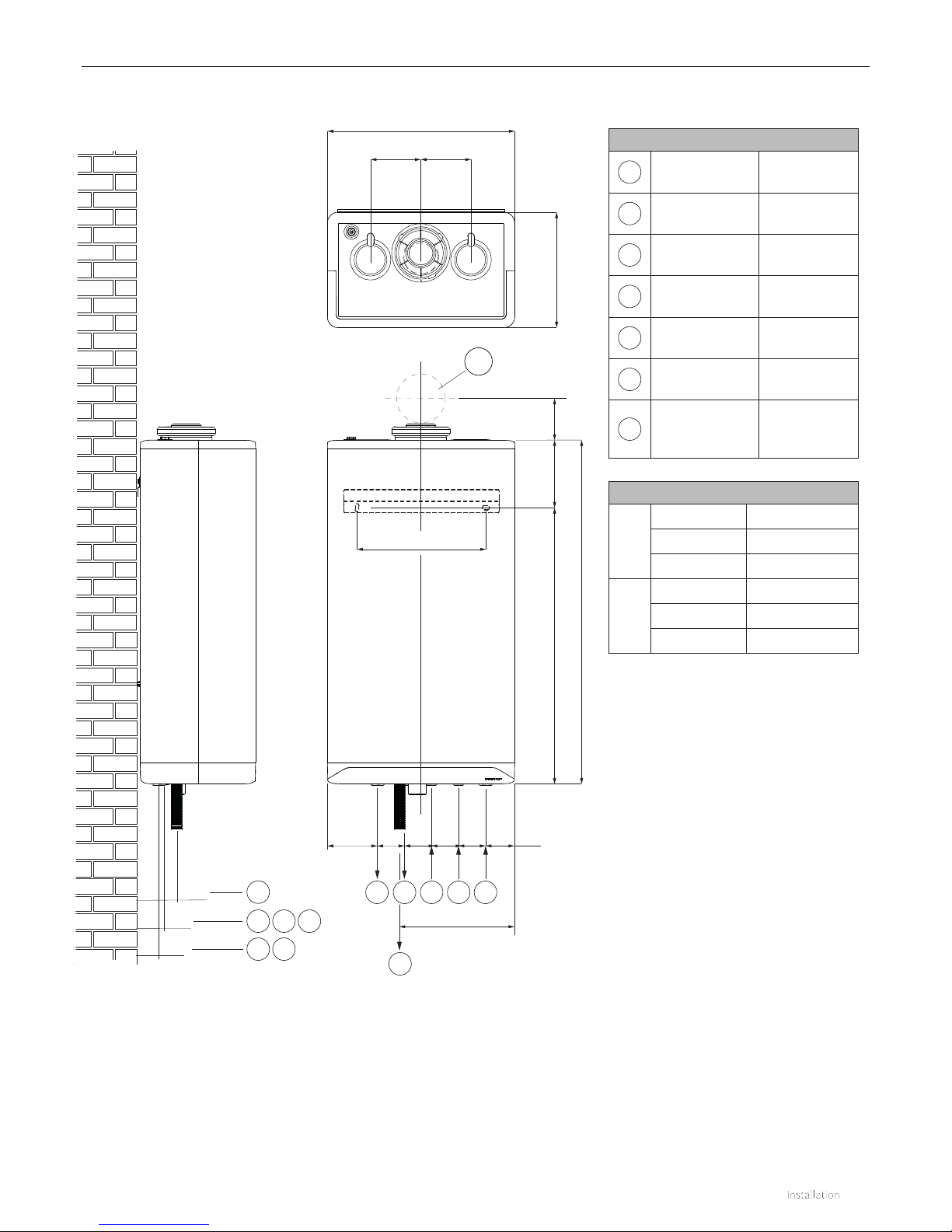
450
277
120
120
6565120 6565 70
275
148 98h
H
=320=
50
65
95
Connections
A
Central heating
flow
3/4"
B
Central heating
return
3/4"
C
Gas flow 1/2"
D
Domestic hot
water - cold
1/2"
E
Domestic hot
water - hot
1/2"
F
Condensation
drain
Ødn25
Z
Flue pipe / Air
supply
Ø60/100
(concentric,
wall terminal )
5 INSTALLATION
A
E C D
B
F
A B
D E
F
Z
C
5.1 Overall dimensions of boiler + assembly bracket
5.1.1 Installing the wall bracket and assembly bracket
Using the corresponding fasteners, attach the wall bracket and
the assembly bracket horizontally to the wall. Refer to the drill
pattern in §5.1 or refer to the installation instructions supplied
with the assembly bracket.
Overall dimensions
h =
650 mm Xtreme 24
650 mm Xtreme 30
710 mm Xtreme 36
H =
766 mm Xtreme 24
766 mm Xtreme 30
826 mm Xtreme 36
Page 16
16
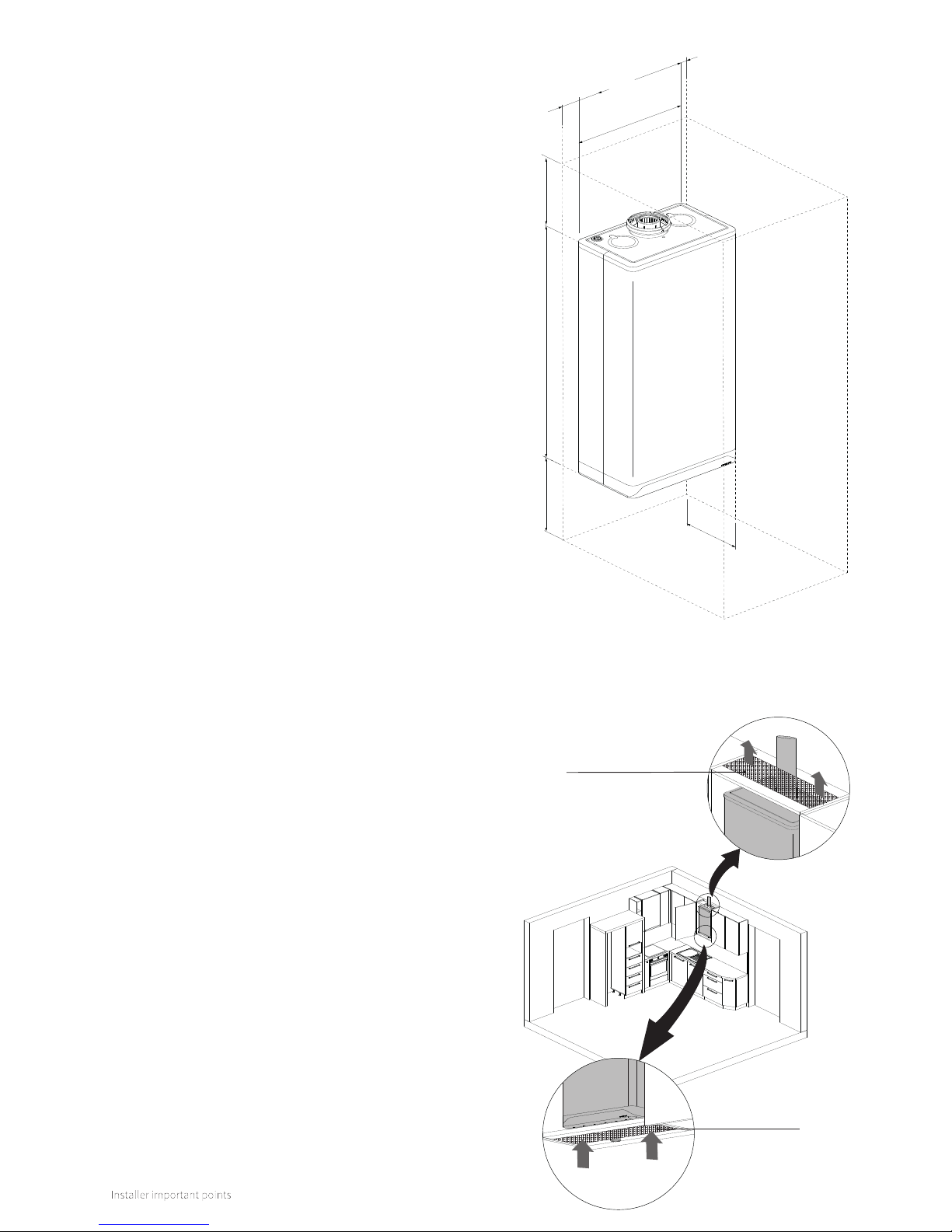
5.2.1 Installation in a kitchen cabinet
The boiler can be placed between two kitchen cabinets or
inside one cabinet. Make sure, however, that there is suicient
ventilation below and above the boiler. If the boiler is placed
inside a cabinet, ventilation openings of at least 50cm2 must
be created above as well as below.
The boiler must be installed on a wall that has suicient
strength to be able to bear the boiler filled with water.
There must be a Earthed fuse spur available at a maximum
distance of one (1) metre from the boiler. The condenstate
must be connected from the boiler and drain away to the
sewer.
To prevent freezing of the condensation drain piping, the boiler
must be installed in a frost-free area.
Make sure the boiler is easily accessible by ensuring that there
is suicient free space surrounding the boiler. This facilitates
the maintenance of the boiler, amongst other things.
5.2 Installation location
at least 50cm
2
at least 50cm
2
min. 200
H
min. 250
min. 50
277
450
min. 10
Page 17
17
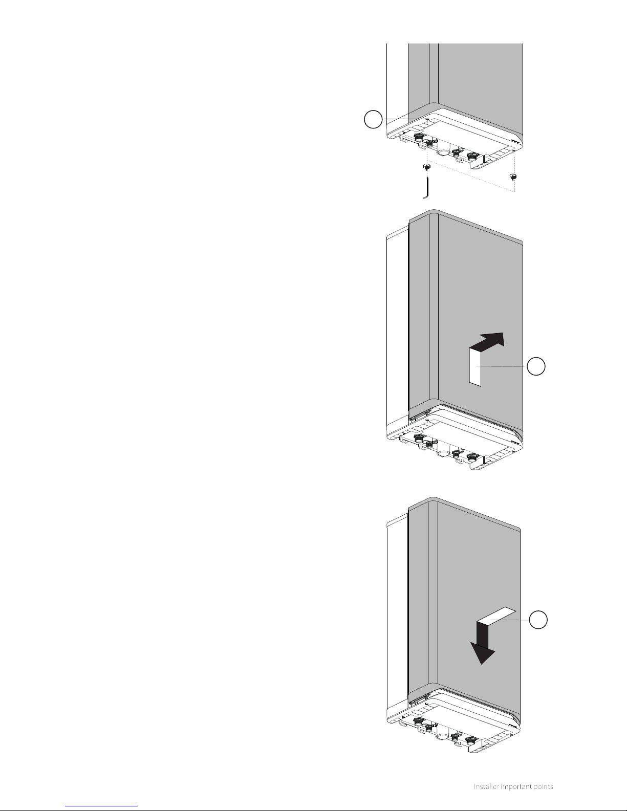
5.2.2 Removing/installing the front panel
► The front panel of the boiler must be removed to perform
various maintenance activities. Do this as follows:
► Unscrew both (lossless) socket screws (1) under the boiler
by using a 5mm socket wrench.
► Slide the front panel (2) upward and then remove it by
pulling it towards you.
1
2
Replace front panel
To replace the front panel, proceed as follows:
► Position the front panel (3) against the boiler and slide
it downwards until it is properly connected to the
boiler.
► Screw tight both socket screws under the boiler using
a 5mm socket spanner.
3
Page 18
18
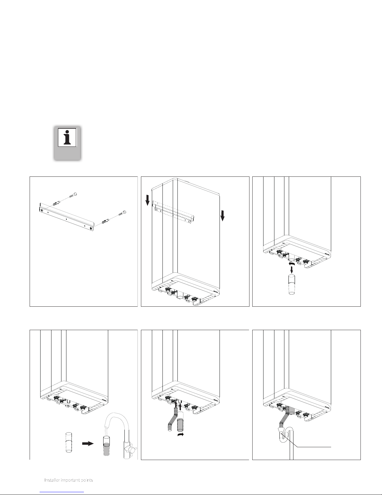
5.3 Installing the boiler
1. Install the wall bracket.
2. Place the boiler: Slide the boiler from the top down, over the
wall bracket.
3. Remove the siphon cup.
4. You must fill the siphon cup just over half full with water.
5. Replace the cup. Install the flexible hose on the spout of the
siphon.
6. Connect the flexible hose of the siphon to a 19 mm solvent
weld pipe. To minimize the risk of freezing the condensate
pipe should be connected internally and terminate to an
internal sol stack (ref.: TB115 Gas Safe & HHIC).
7. Install the air supply duct and the flue (see §6.6).
COMMENT
► The Intergas Xtremehas a boiler-specific
siphon cup. Ensure that the proper
version is ordered upon replacement.
(Item no 510054)
1. Assemble wall bracket
4. Fill siphon cup 5. Replace siphon cup in position and
attach flexible hose
6. Connect the flexible hose to the
sewer via an open connection.
2. Place boiler 3. Remove siphon cup
Open connection
to sewer
Page 19
19
6.1.2 Thermostatic radiator valves
6.1.1 Expansion vessel
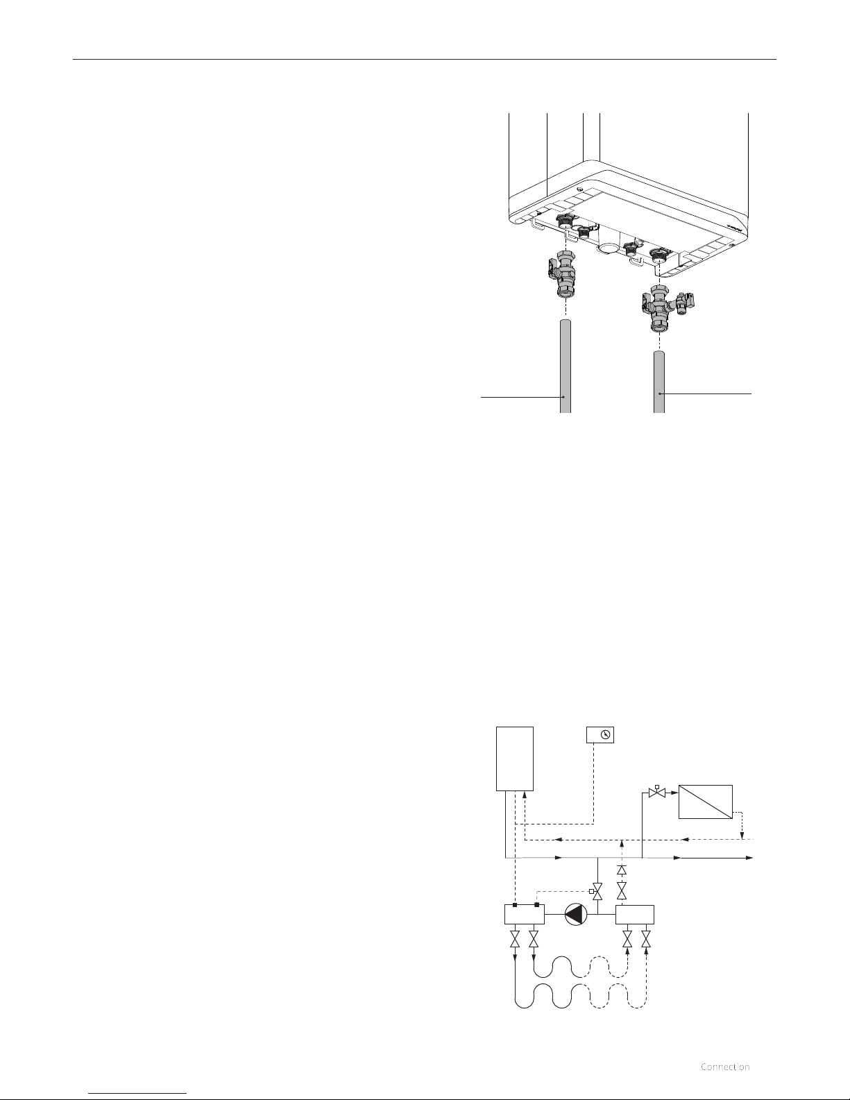
► Flush the central heating system thoroughly.
► Fit the flow and return pipes to the isolation valves.
► All pipes must be fitted unstressed in order to prevent pipes
from ticking.
► Existing connections must not be twisted, in order to avoid
leakages.
The CH system should be equipped with:
► A drain tap in the return pipe immediately below the
appliance.
► A drain tap at the lowest point(s) of the installation.
► A non return valve, if pipes run upwards at a short
distance from the appliance. This avoids the occurrence of
thermosyphon eect during DHW operation mode.
If all radiators have thermostatic radiator valves or valves that
can be closed to separate the flow completely from the return,
a minimum amount of water circulation must be ensured by
the installation of bypass piping, for example (also see §8.5).
The appliance is fitted with a expansion vessel adequate for a
system with a water volume not exceeding 100 litres, typically 8
radiators. For larger volume systems, an additional expansion
vessel must be fitted. Contact Intergas for advice in these cases.
6 CONNECTION
6.1.3 Floor heating
Floor heating with pump
For eective operation of the DHW supply any undesired
circulation through the appliance as a result of a second pump
in the CH circuit must be avoided.
Connect the floor heating system in a hydraulically neutral
manner to the appliance, or equip the CH circuit with an
electric shut-o valve or check valve to prevent flow
through the appliance when there is no CH request for heat.
Make sure there is a minimum of water circulation; see §8.5.
Underfloor heating connection diagram
A. Boiler
B. Central heating pump
C. Thermostatic control valve
D. Spring-operated non-return valve
E. Electric shut-o valve 230V~
F. Radiators
G. Room/clock thermostat
H. Maximum thermostat
A
G
H
F
C
B
C
E
D
6.1 Connecting the central heating system
Return pipe
Flow piping
Page 20

20
6.1.4 LT/HT zone system
The central heating system can be divided into two groups,
each with a dierent heating temperature, for example a hightemperature zone (HT) with radiators and a low-temperature
zone (LT) with underfloor heating system without its own
circulation pump.
Both zones must have their own room thermostat. LT/HR
zone control is activated by the adjustment of a number of
parameters.
There are two dierent installation sets available for installing
the LT/HT zone system:
► Installation set with two-way valve (item no 093697).
► Installation set with three-way valve (item no 093707).
Operational principle
The valve divides the heat over both zones. Both zones have
their own room thermostat and are alternately (time-limited)
heated through switching over the valve.
IMPORTANT
► Ensure that the external pump pressure
of the central heating pump in the boiler
is taken into consideration during the
design phase of the underfloor heating.
► If the radiators in the HT zone have
thermostatic radiator valves, this zone
must have a bypass valve.
Page 21
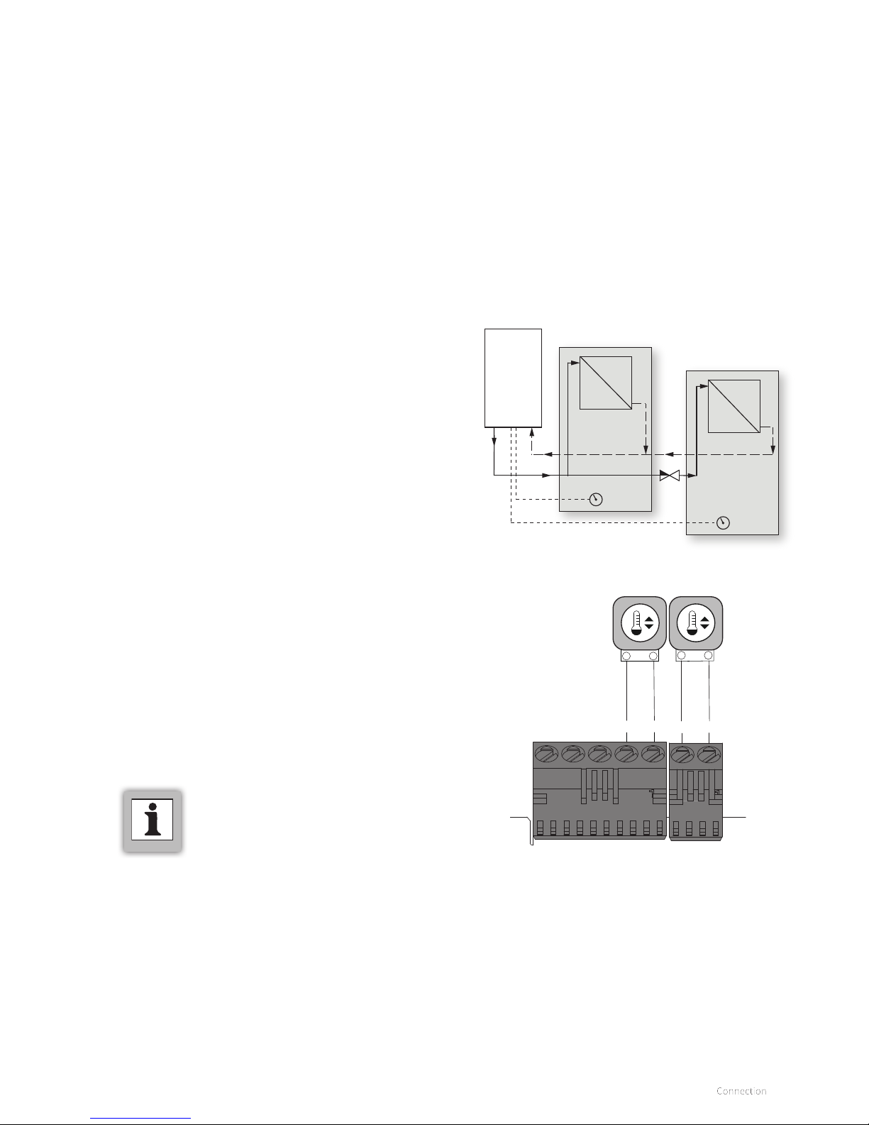
21
Operational principle
If the room thermostat switches o the boiler because another
heat source is heating the room, it is possible that the other
rooms will cool down.
This can be prevented by dividing the central heating system
into two groups. The group with the external heat source (Z2)
can be closed o from the main circuit with an electric shut-o
valve. Both groups have their own room thermostat.
Note: This ‘external heat source’ control can only be applied if
no external boiler must be heated.
Installation manual
► Place the shut-o valve (B) according to the connection
diagram.
If an OpenTherm or an on/o thermostat is used:
6.1.5 Division of central heating system in groups with extra heat source
Connection diagram ‘external heat source’
control
A. Boiler
B. Electric shut-o valve 230V~
C. Radiators
T1. Room thermostat Group 1
T2. Room thermostat Group 2
Z1. Group 1
Z2. Group 2
A
Z1
B
C
T
1
Z2
C
T
2
COMMENT
► All types of thermostats (OpenTherm, on/
o or RF) can be used in both groups.
12
X13 X12
12
12
12
T2 T1
► Connect the room thermostat of Group 1 (T1) to Connector
X12 1/2.
► Connect the room thermostat of Group 2 (T2) to Connector
X13 1/2.
► Change parameter P081 (see §8.3).
If an RF thermostat is used:
► Connect the RF thermostat using the RF menu; see §7.1.4.
The RF thermostat can only be used for Group 2.
► Change parameter P081 (see §8.3).
Connect thermostats Groups 1 and 2
Page 22
22
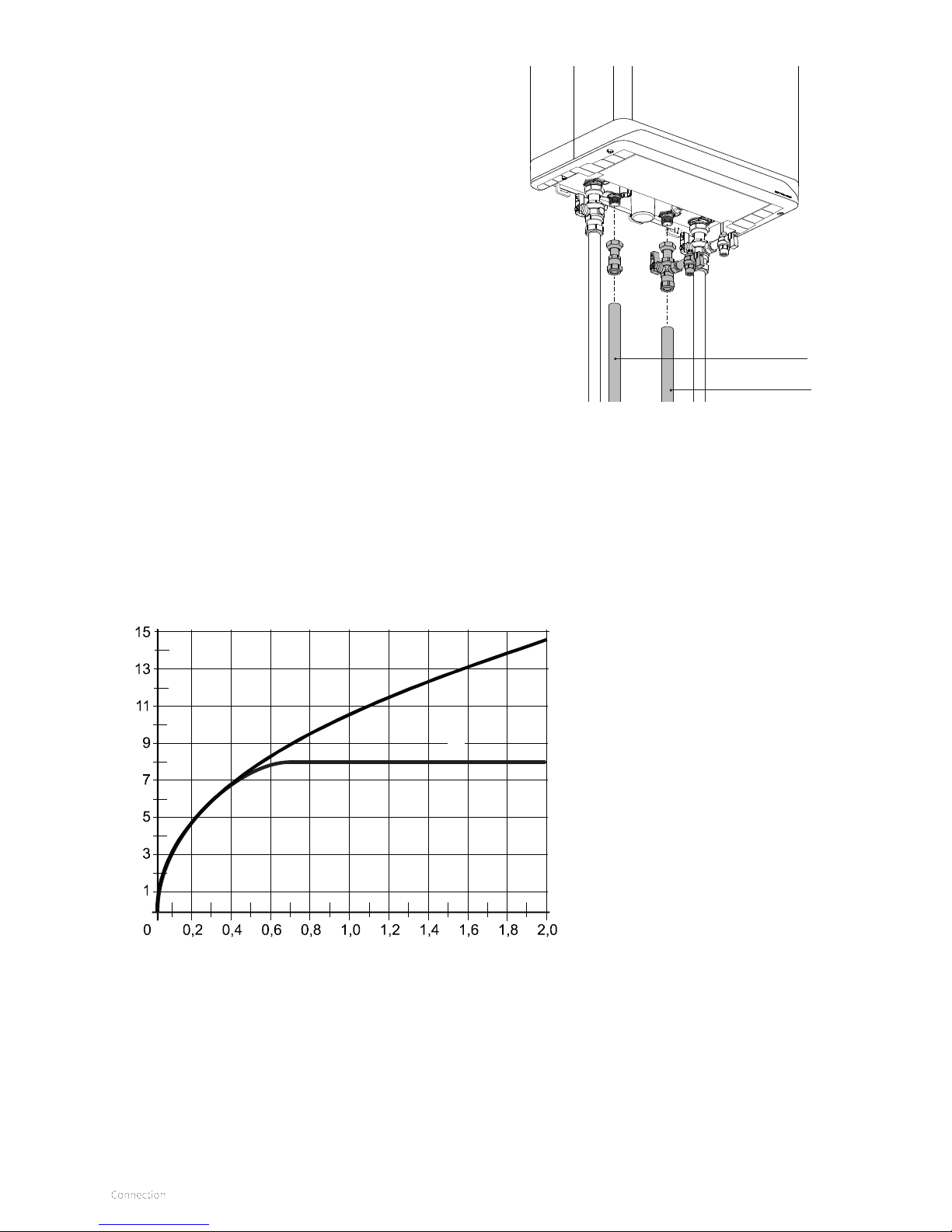
6.2.1 DHW circuit resistance graph
► Flush the installation thoroughly to clean (please refer to
current Standard Codes of Practice).
► Fit the cold and hot water pipes into the shut o valve and
the elbow.
► Existing connections must not be twisted, in order to avoid
leakages. Make sure the compression fittings are tightened
thoroughly to prevent leakage.
Comments
► The specific pipeline length with a piping diameter of
12/10mm or 15/13mm is 30 meters and 17.7 meters,
respectively.
► If the boiler is only used for the domestic hot water facility,
the heating function can be switched o. Parameter P001
must then be changed from 0 to 2. In this case, the central
heating system does not need to be connected or filled.
► If the boiler is out of order and disconnected from the
electricity network during the winter months, the water
must be drained to prevent freezing. Disconnect the
domestic hot water connections immediately directly under
the boiler.
► The Xtreme 24 is equipped with a flow restrictor with a
nominal value of 8l/min. The Xtreme 30 and Xtreme 36 do
not have this feature. If desired, this can be ordered from
Intergas as an option.
The Xtreme 36 allows larger volume flows with high water
pressures; to ensure an exhaust temperature of 55°C, the
DHW facility has to be set at 9 l/min.
6.2 Connection of domestic hot water
Cold water pipe
Water supply system (bar)
Domestic hot water
piping
Flow rate (l/min)
B, C
A
A. Xtreme 24
B. Xtreme 30
C. Xtreme 36
Page 23
23
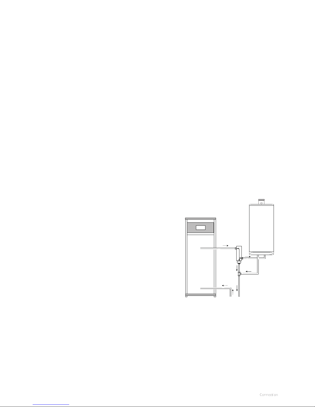
A
B
C
D
E
F
A. Heat pump
B. Boiler
C. Switch valve
D. Cold water inlet
E. DHW temperature of heat pump
F. DHW temperature of domestic hot water
Connection diagram of boiler with heat pump boiler
Installation:
The combination must be connected according to the
connection diagram. The following points are important to
guarantee a correct operation of the combination.
Thermostatic switch valve:
The thermostatic switch valve used is a modified valve that
meets the specific requirements to which the combination
heat pump boiler and Intergas Xtremeare subject. For the
correct operation of the combination, the switch valve has a
fixed temperature setting. The thermostatic switch valve can be
ordered from Intergas (item no: 065127).
6.2.2 Boiler with heat pump boiler
The boiler is suitable for use in combination with a heat pump
boiler.
If the exhaust temperature of a heat pump boiler is lower than
55°C, the Intergas Xtrememakes sure that the domestic hot
water from the heat pump boiler is post-heated under HE
conditions.
Operational principle:
The domestic hot water connection of the heat pump boiler
is connected to the mix input of the thermostatic switch valve
(see the principle diagram). If the DHW temperature of the
boiler is higher than the set temperature of the switch valve,
the heat pump boiler will be tapped. Because the switch valve
is not fully closing, a small amount will also run through the
Intergas Xtreme(about 10% of the total flow).
As soon as the exhaust temperature of the heat pump boiler
becomes lower than the set temperature of the switch valve,
the flow through the Intergas Xtremewill increase. If the flow
becomes greater than the domestic hot water threshold of
the Intergas Xtreme, the boiler will start domestic hot water
demand.
When the exhaust temperature of the heat pump boiler has
become lower than the set temperature of the switch valve
minus 12K, almost the entire domestic hot water flow goes
through the Intergas Xtreme. The small leakage flow is now
taken from the heat pump boiler. Aer the entire switching of
the switch valve, the domestic hot water flow will be limited by
the Intergas Xtreme.
Page 24
24
Domestic hot water inlet pressure:
For a flow volume of 20 litres per minute, the initial pressure
must be a minimum of 2.3 bar. The allowed domestic hot
water operational pressure for the combination may be a
maximum of 6 bar. A safety group (6 bar) must be installed for
this purpose.
Maximum flow volume:
If the domestic hot water flow is greater than 20 litres per
minute, the Intergas Xtremewill start domestic hot water
demand, regardless of the exhaust temperature of the heat
pump boiler.
Maximum temperature setting of the heat pump boiler:
The temperature of the heat pump boiler may not be set higher
than 60°C.
Position of thermostatic switch valve:
To prevent the thermostatic switch valve being influenced too
much by the surrounding air, this valve must be placed in a
vertical position and as close as possible to the domestic hot
water connection of the boiler (maximum distance of 100mm).
This prevents the boiler operating with each tap request.
Influence of water flows:
To prevent the flow being influenced by the Intergas
Xtremeduring the switching of the valve, the domestic hot
water ‘out’ pipeline of the combination must run straight (see
connection diagram [F]).
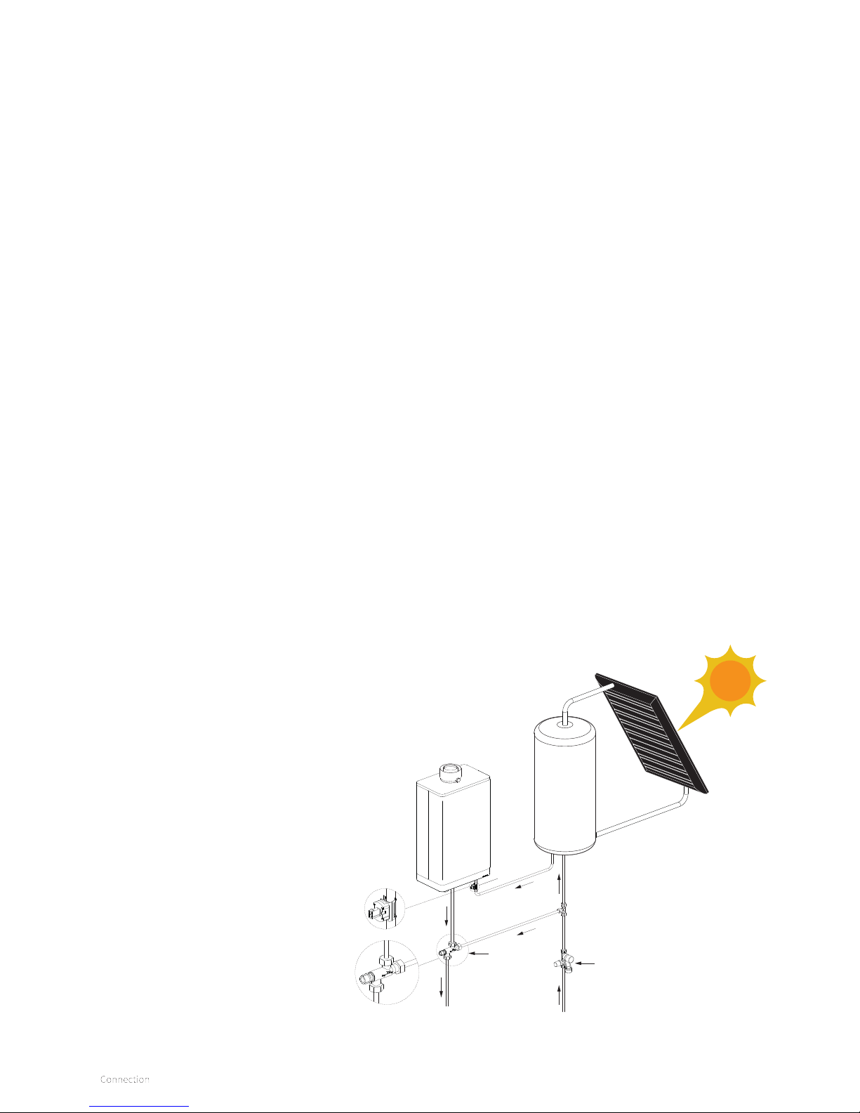
6.2.3 Boiler with Pre-Heated Solar Boiler)
A connection set and a thermostatic mixing valve are available
to order for this purpose.
Comment:
The cold water sensor must be connected to Connector X13
4/5. When combined with a solar energy system, a thermostatic
mixing valve, set at 62.5°C, must always be placed aer the
boiler.
► Pre-heated Solar boiler conversion set item no 090347
► Thermostatic mixing valve item no 842177
C
C
H
D
B
A
C
E
G
F
I
ART.NR.
842177
A
Connection diagram:
A. Boiler
B. Solar boiler
C. Cold water
D. Safety group
E. T max. 85°C
F. Domestic hot water
G. Thermostatic mixing valve 35°C-65°C
(set at 62.5°C)
H. Domestic hot water mixed
I. Cold water sensor
Page 25
25
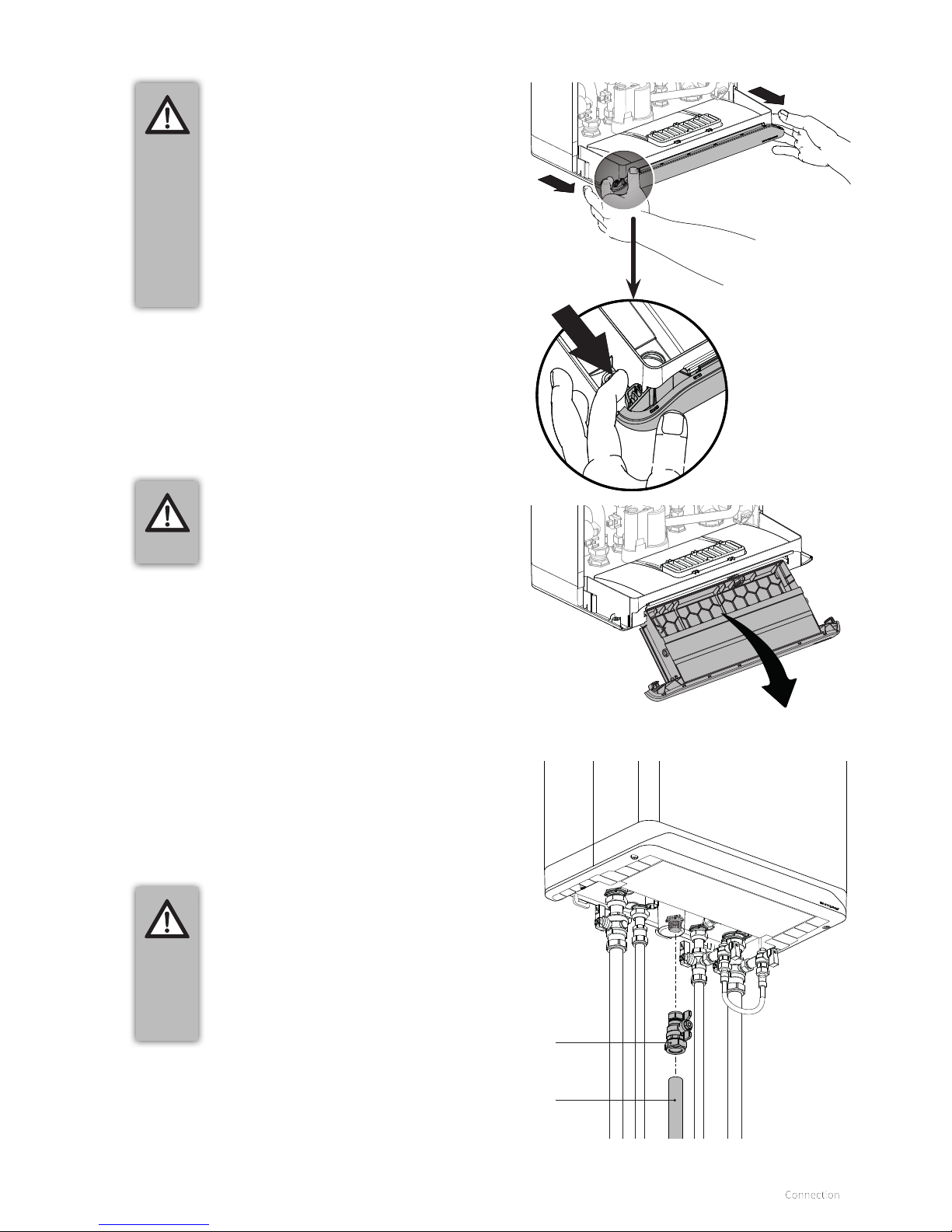
6.3 Electrical connection
► Fit the gas pipe into the gas valve and tighten this
thoroughly.
► Make sure that the gas pipe is fixed to a rigid surface.
► Open the main gas valve and purge the system.
► Check all connections for leakage.
CAREFUL
► Before starting the work, close the main
gas valve.
► The boiler is intended exclusively to be
installed on a gas supply with a meter
with gas pressure regulator.
► When pollution in the gas is to be
expected a gas filter has to be placed in
the gas pipe to the boiler.
6.4 Gas connection
Gas valve
Main gas
piping
Gas valve
If maintenance activities to the electric circuit must be
performed:
► Remove the front panel (see §5.2.2) and pull the burner
controller unit forward; the burner controller will then tilt
downwards.
► Consult the electrical schematic in §11.1 for making the
connections.
► Aer the desired connections have been made, slide the
burner controller back in the boiler (until the le and right
safeties are again locked) and replace the front panel on the
boiler; see §5.2.2.
► Aer making the desired connections plug the appliance
into an earthed wall socket
CAREFUL
► A fused spur or an unswitched socket
must be located no more than 1 metre
from the appliance.
► For installation in damp rooms a fixed
connection is obligatory.
► When working on the electrical circuit
always isolate the electric supply.
► When the power mains cord must be
replaced, this must be ordered from
Intergas.
CAREFUL
► The Xtreme complies with IPX4D. To
ensure this, cable grommets should
be used when making electrical
connections.
Page 26
26
6.5.1 Connecting Modulating OpenTherm thermostat
6.5.2 Connecting on/o room thermostat
6.5.3 Connecting 230V room thermostat
6.5 Connecting room thermostat
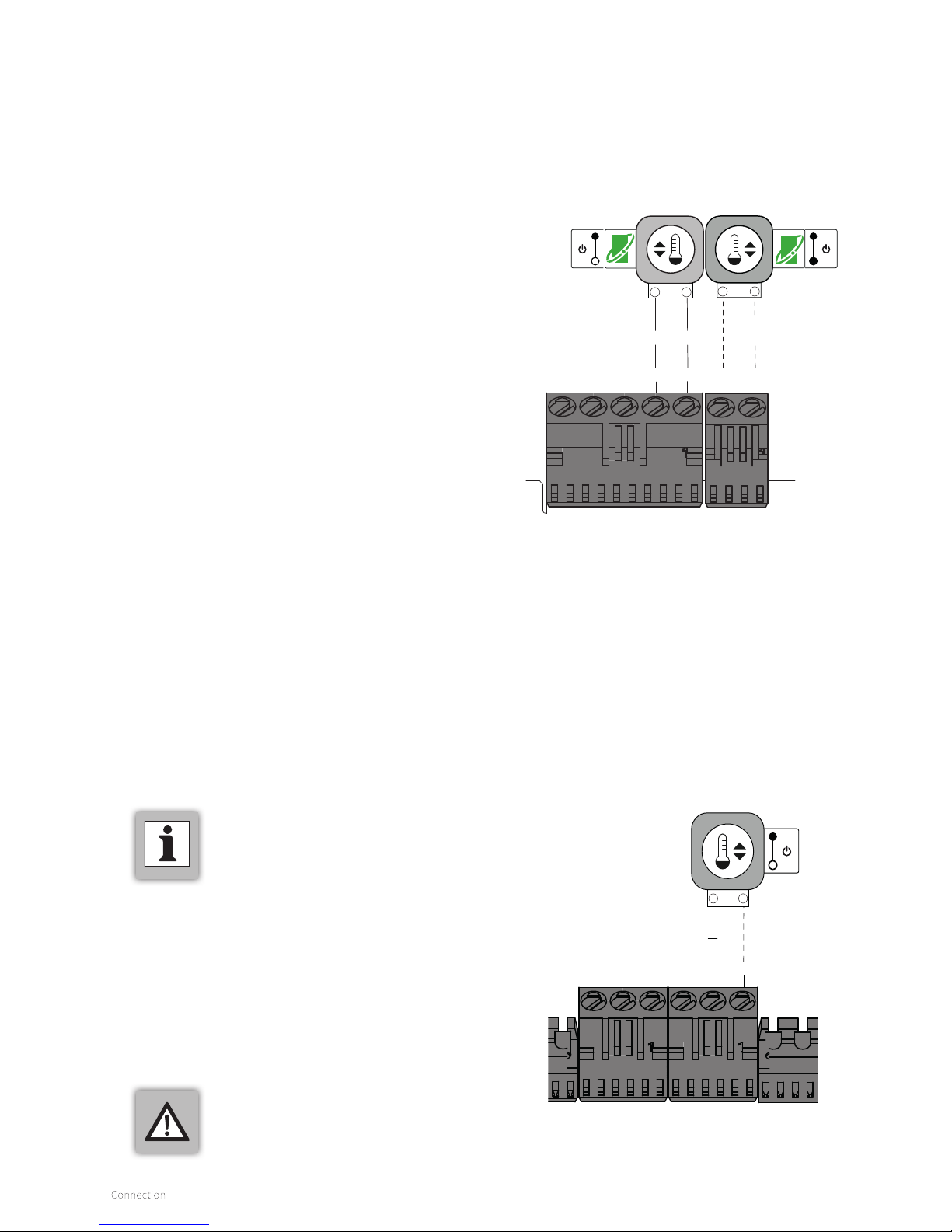
The boiler is standardly provided with an OpenTherm
connection. This allows the connection of modulating
OpenTherm thermostats without any additional modifications.
The Xtreme is also suitable for OpenTherm Smart Power.
► Place the thermostat is the room that functions as a
reference point (in general, the living room).
► Connect the modulating thermostat to Connector X13 1/2
(also see §11.1); the polarity of the wires is not important in
this situation. The boiler oers the possibility of connecting
two OpenTherm thermostats. Connect a 2nd OpenTherm
thermostat to connector X12.
If you would like to make use of the domestic hot water on/
o switch function of the OpenTherm thermostat, the DHW
comfort function must be set to ‘eco’ of ‘on’ (see §8.1.2) and
parameter P074 must be set to 0.
For more information, consult the manual of the room
thermostat.
The boiler is suitable for connection to the following room
thermostats:
► OpenTherm (OT) thermostat
► On/o thermostat
► RF thermostat; see §8.1.4.
The boiler is suitable for connection to a 2-wire on/o room
thermostat.
► Place the thermostat is the room that functions as a
reference point (in general, the living room).
► Connect the 2-wire room thermostat to Connector X13
1/2 (also see §11.1); the polarity is not important in this
situation. A second on/o thermostat can be connected to
Connector X12, if desired.
To be connected to contacts 1 and 2 of connector X3.
► Place the thermostat is the room that functions as a
reference point (in general, the living room).
► Connect the 2-wire room thermostat to Connector X3
1/2 (also see §11.1); the polarity is not important in this
situation.
Connecting OpenTherm and/or on/o
room thermostats
Connecting 230V room thermostat
12
LS
X13 X12
12
12
12
On
O
On
O
X4 X3 (230V)
12
On
O
12
► If both an OpenTherm as well as an on/
o thermostat is connected, the on/o
thermostat has priority with respect to
the OpenTherm thermostat.
IMPORTANT (HIGH VOLTAGE)
► Isolate the appliance from the electrical
supply before connecting the thermostat.
Page 27
27
6.5.4 Connecting outdoor sensor
The boiler has a connection for an Intergas outdoor sensor. The
outdoor sensor must be used in combination with an on/o or
OpenTherm room thermostat.
In principle, any on/o or OpenTherm room thermostat can
be combined with an Intergas outdoor sensor. With an on/
o thermostat, the boiler will adjust the flow temperature
according to the set heating line. With an OpenTherm
thermostat, this determines the influence on the flow
temperature.
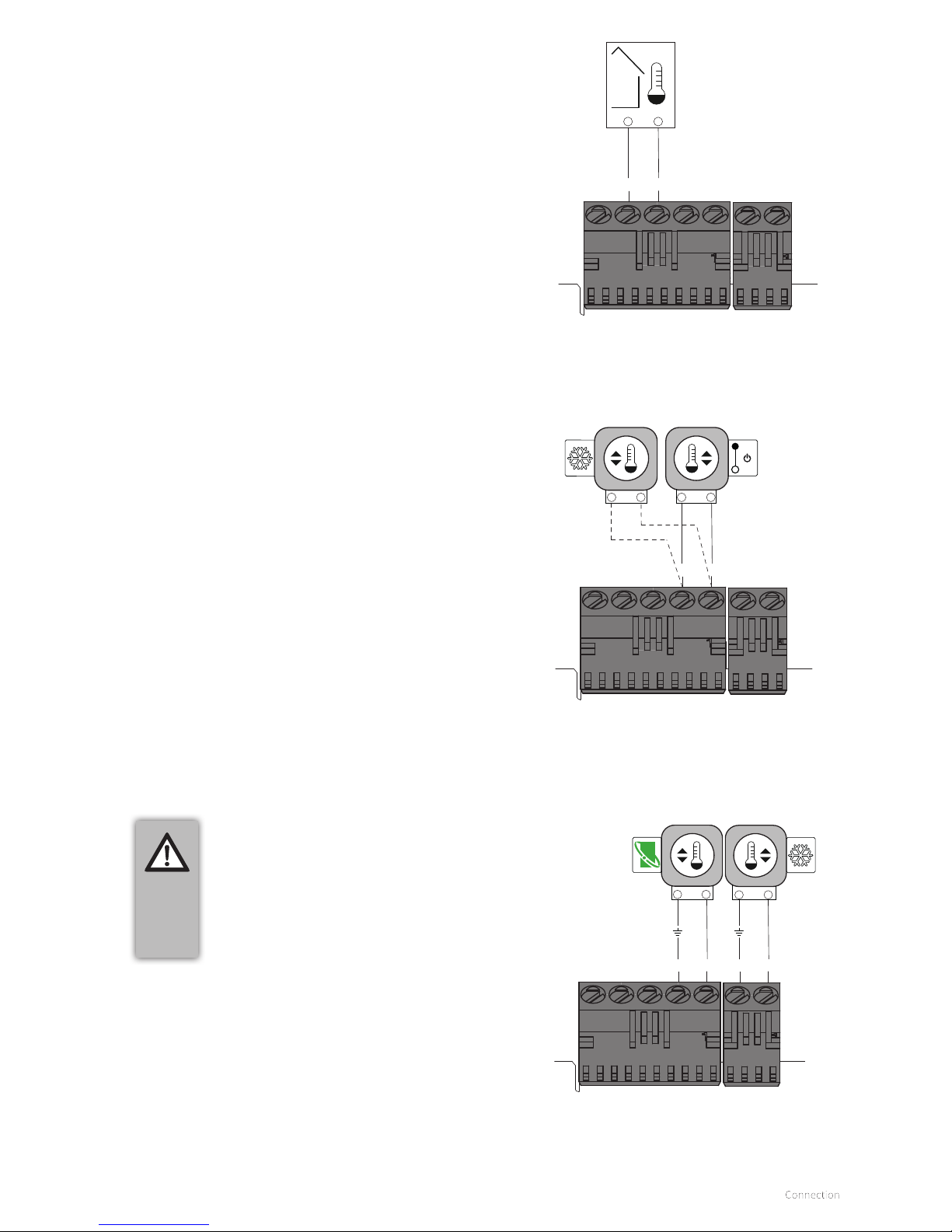
► Connect the outdoor sensor to Connector X13 3/4 (also see
§11.1).
For the heating line graph, see §7.6.
34
X13 X12
3
4
► To prevent freezing of the condensation drain piping, the
boiler must be installed in a frost-free area.
► To prevent freezing of the boiler, the boiler is equipped with
frost protection. If the temperature of the water in the heat
exchanger becomes too low, the pump will run (the burner
is switched on if needed) until the temperature of the water
is again at a frost-free level.
Comment
If an on/o room thermostat will be used, secure a frost-hazard
area from frost in combination with
a frost thermostat. The radiator valve in the frost-sensitive area
must be opened.
► In frost-hazard areas (for example, a garage), place a frost
thermostat.
► Connect the frost thermostat together with an on/o room
thermostat or RF thermostat parallel to Connector X13 1/2
(also see §11.1).
6.5.5 Frost protection
CAREFUL
► With the use of an OpenTherm
thermostat, a frost thermostat may not
be connected in parallel on Connector
X13. In that case, connect the OpenTherm
thermostat to Connector X13 and the
frost thermostat to Connector X12.
If the (external) frost thermostat is used in the installation and
it is connected to the boiler, it is not active when the boiler is
switched o.
12
X13 X12
1212
On
O
12
X13 X12
12
12
12
Connecting outdoor sensor
Frost thermostat and on/o thermostat
parallel connection
Frost thermostat and OpenTherm thermostat
connection
Page 28
28
45
X13 X12
4
5
X15
X14
X13
http://www.intergasverwarming.nl
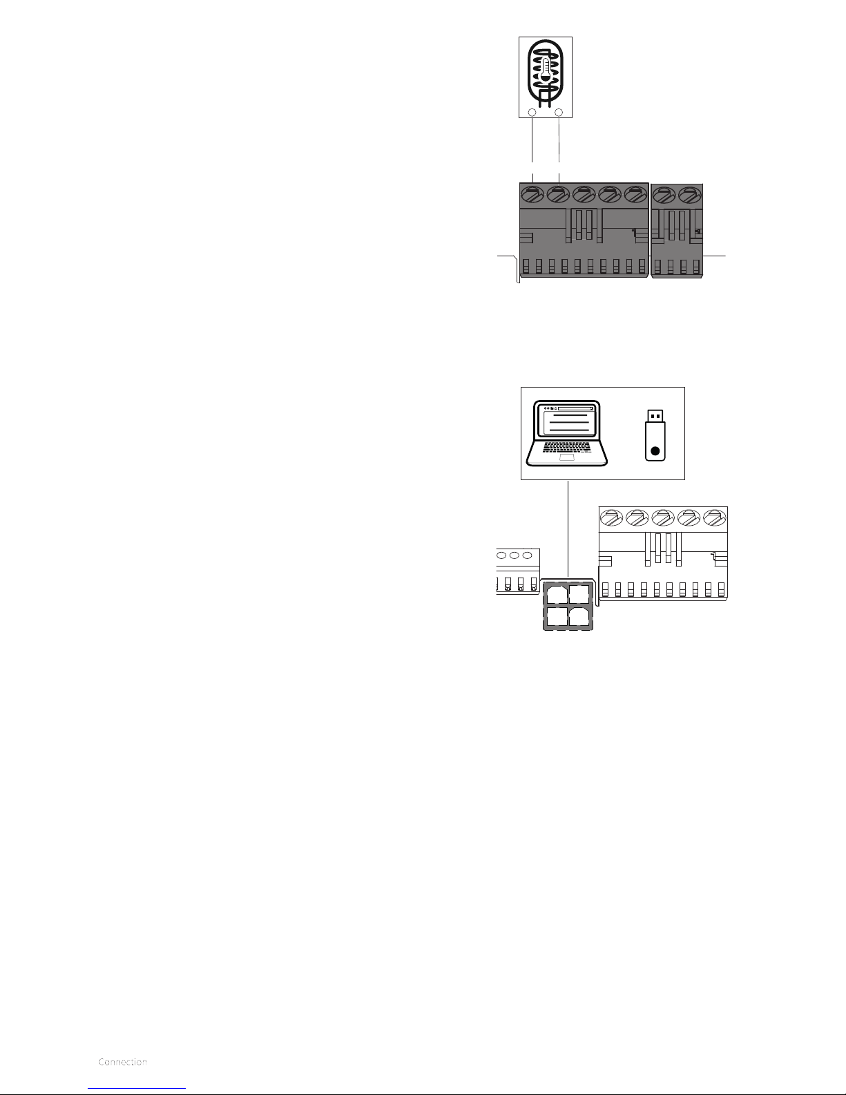
► The boiler sensor/thermostat can be connected to
Connector X13 4/5 (also see §11.1).
6.5.6 Connecting boiler sensor/thermostat
The automatic has an interface for a PC. A PC can
communicate with the boiler through a special cable, or
wirelessly through the Intergas USB dongle, along with
associated soware. This facility allows the behaviour of the
boiler controller, the boiler and the heating system to be
followed over a longer period of time.
► Connect the cable to Connector X14 (also see §11.1 ).
6.5.7 PC interface
6.5.8 Comfort Touch
Boiler sensor/thermostat
connection
PC connection
It is possible to combine the Xtremewith the Intergas Comfort
Touch wireless and Comfort Touch OpenTherm (available as an
option). This set consists of a LAN2RF gateway and a connection
set. The LAN2RF gateway provides a connection between an
internet router and the boiler, so that the boiler can be monitored
and managed at a distance (via a web server) using the Comfort
Touch service app.
The Comfort Touch is available via the regular merchant.
If the end user also wants to make use of the Comfort Touch
possibilities of the Xtreme, the set is also available with a
Honeywell Round thermostat. For the end user, a consumer
version of the Comfort Touch app is available.
The Comfort Touch service and consumer app can be
downloaded from both the Google Play Store and the Apple App
Store.
Page 29
29
► For the installation of the flue and air
supply duct material, see the manual
included with the materials. Contact the
manufacturer of the relevant flue and
air supply duct materials for extensive
technical information and specific
assembly instructions.
► Only stainless steel or plastic (PP T120)
flue material is allowed.
► Make sure that the socket connections
of the flue and air supply duct materials
are correctly sealed. Improper fastening
of the flue and the air supply duct
can lead to hazardous situations or
result in personal injury. Check all flue
components for tightness.
► Don not use screws or parkers to mount
the flue system as leakage can occur.
► Do not use any sort of grease when
mounting the pipe system. Use water
instead. The sealing rubbers can be
negatively aected when grease is
applied.
► Do not mix any components, materials
or ways of coupling from dierent
manufacturers.
6.6 Flue and air supply duct
6.6.1 Dra, materials and insulation
Piping Diameter Material
Flue Ø100/60 mm According to Table 4 of NPR3378-46 (C-category appliances)
NPR3378-47 (B-category appliances)
Only stainless steel or PP T120.
Page 30
30
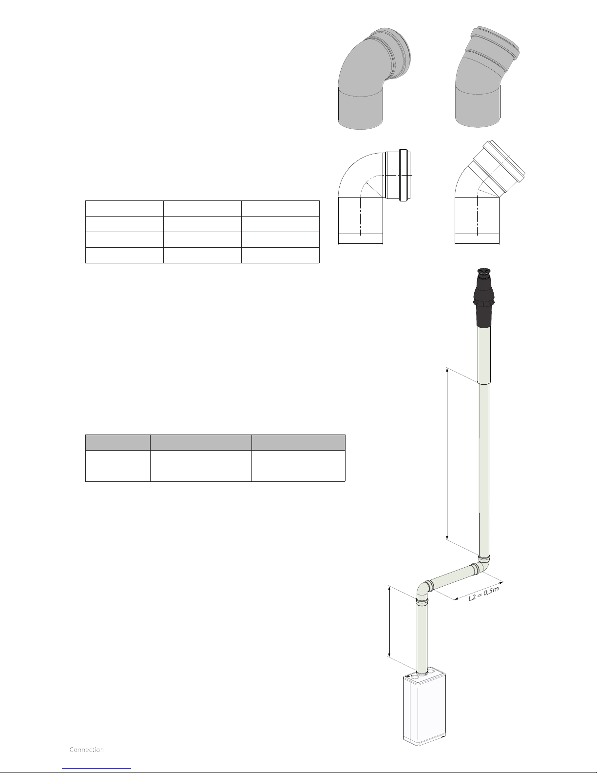
Piping Pipeline length Total pipeline length
Flue L1+L2+L3+(2x2m) 12 m
Air supply duct L4+L5+L6+(2x2m)+(1x1m) 13 m
Comments
► The total pipeline length is:
The sum of the straight pipeline lengths + the sum of the
replacement pipeline lengths of curves/knees are together
25meters.
► If the allowed length of air supply duct pipe and flue pipe
are together 80metres (excluding the length of the combi-
pipe wall terminal or the twin-pipe wall terminal), then the
calculation falls within the allowed pipeline length.
L1 = 1m
L3 = 6,5m
As the resistance of the flue and air supply duct pipes
increases, the capacity of the boiler will decrease. The allowed
decrease in capacity is a maximum of 5%.
The resistance of the air supply duct and the flue depends
on the length and diameter of the piping system and all
associated components. For each boiler category, the total
allowed pipeline length of the air supply duct and flue is given.
The specification of the pipeline length in meters assumes Ø80
mm piping.
D D
R
R
R/D = 0,5R/D = 0,5
6.7 Pipeline lengths
6.7.1 Replacement lengths
6.7.2 Example calculation
Curve of 90° R/D=1 2 m
Curve of 45° R/D=1 1 m
Knee of 90° R/D=0.5 4 m
Knee of 45° R/D=0.5 2 m
Contact the manufacturer for check calculations for the
resistance of the air supply duct and flue system and for the
wall temperature at the end of the flue system.
Page 31
31
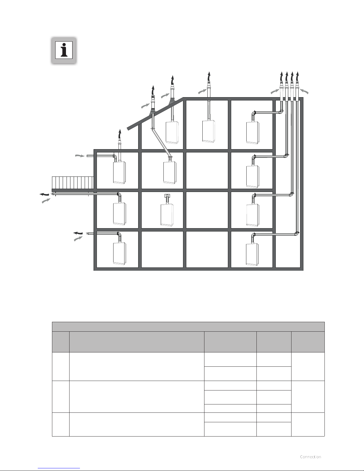
6.8 General layout of the flue
C33
C53
C13
C13
C33
C33
C13
C33
C33
C33
C33
The following drawing shows all possible situations schematically.
COMMENT
► The following schematic drawings serve
as examples and the details may dier
from the actual situation.
Note for flue systems
Cat. Note according to CE Materials
Supplier/
Inspection
requirement
Applicable
to Xtreme
C13 The terminal is located in the façade; the inlet for the air
supply duct is located in the same pressure area as the
terminal. Example: combined façade terminal
Terminal Intergas
Yes
Other components Gastec QA or
Intergas
C33 The terminal is located above the roof; the inlet for the air
supply duct is located in the same pressure area as the
terminal of the flue piping.
Terminal Intergas
Yes
Terminal at the
prefab chimney
Gastec QA or
Intergas
Other components
C53 Closed unit, connected to separate air supply duct and
flue channels, terminated in various pressure zones. See
the installation manual for the possibilities.
Intake grille Intergas
Yes
Other components
and exhaust cap
Gastec QA or
Intergas
Page 32
32
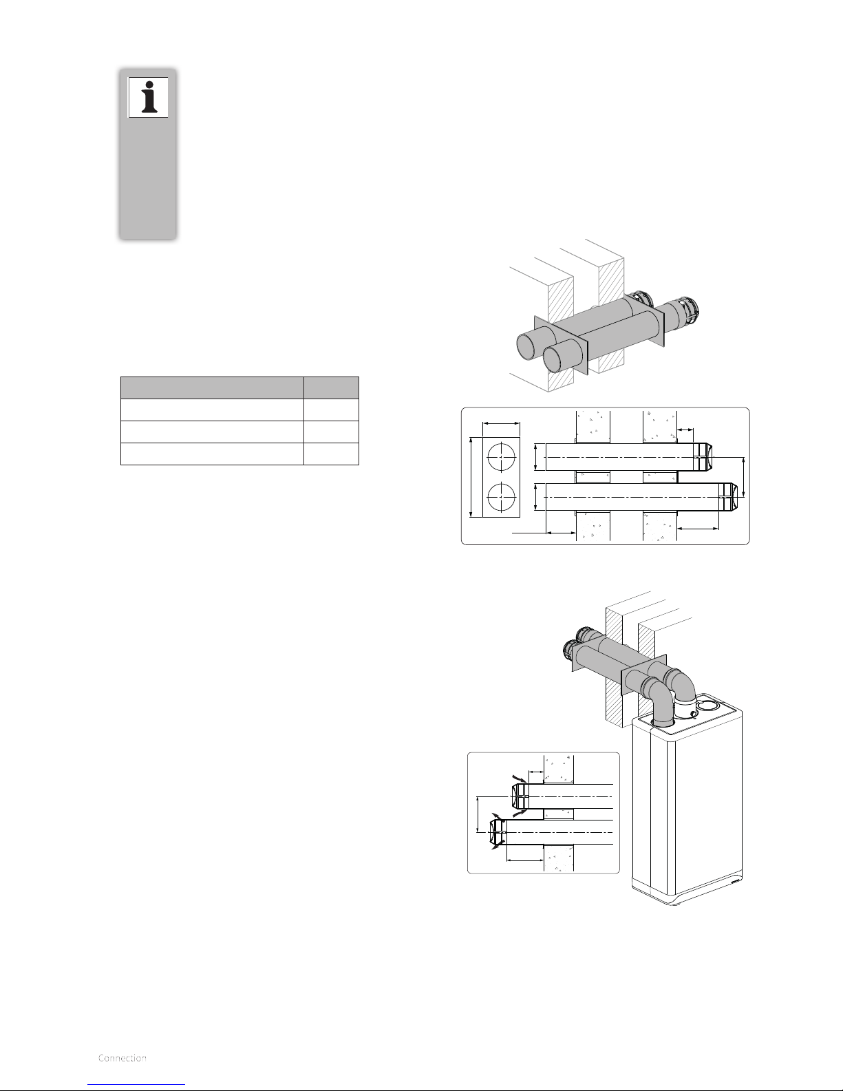
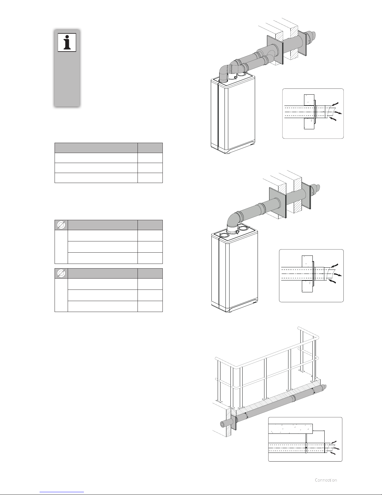
► Intergas twin-pipe horizontal wall terminal (item no 09027).
To be extended, in the case of a balcony terminal, with one
or two standard pipes (Ø80 mm).
Allowable pipeline length
Air supply and flue system including the length of the twin-pipe
wall terminal.
Boiler Length
Intergas Xtreme 24 100 m
Intergas Xtreme 30 850 m
Intergas Xtreme 36 80 m
min. 90
Ø80 Ø80
120
110
240
50
125
50
120
125
Assembly of twin-pipe wall terminal
► Create two openings of Ø90 mm at the location of the
terminal.
► Shorten the twin-pipe wall terminal to the correct length.
► Slide the supply and exhaust pipe in the openings.
► Close the openings with the wall covers.
► Install the outlet grilles on the supply and exhaust pipe.
► Attach these to the pipes.
► Assemble the twin-pipe wall terminal, taking into account
the air supply duct goes to the exterior at an angle and the
flue goes to the boiler at an angle.
COMMENT
► Pipes for the connection of the air supply
duct and the flue between the boiler and
the combi-pipe wall terminal must have a
diameter of Ø80 mm.
► When using a wall terminal, the boiler
must be equipped with a flue gas nonreturn valve (item no 090417).
► The individual flue pipe (Ø80) must be
constructed of stainless steel or plastic
PP T120.
6.8.1 Wall terminal with twin-pipe horizontal terminal C13
Page 33
33
Assembly of combi-pipe horizontal terminal
► Create an opening of Ø130 mm at the location of the
terminal.
► Shorten the combi-pipe wall terminal to the indicated
length.
► Assemble the outlet grille and attach this to the internal
pipe.
► Slide the combi-pipe wall terminal in the opening and
attach rosettes to cover the opening.
► Assemble the combi-pipe wall terminal to the boiler at an
angle.
COMMENT
► Pipes for the connection of the air supply
duct and the flue between the boiler and
the combi-pipe wall terminal must have a
diameter of Ø80 mm.
► It is recommended to use a flue gas non
return valve.
► The individual flue pipe (Ø80) and/
or the internal pipe of the combi-pipe
wall terminal / extension pipe must be
constructed of stainless steel or PP T120.
Allowed pipeline length
► Twin-pipe
Air supply duct and flue pipe together, excluding the length of
the combi-pipe wall terminal.
Boiler Length
Intergas Xtreme 24 100 m
Intergas Xtreme 30 85 m
Intergas Xtreme 36 80 m
► Concentric
Air supply duct and combustible gas exhaust pipe
together, excluding the length of the combi-pipe wall
terminal.
125
6.8.2 Façade combi-pipe horizontal terminal C13
Boiler C13
Ø60/100
Intergas Xtreme 24 10 m
Intergas Xtreme 30 10 m
Intergas Xtreme 36 10 m
Boiler C13
Ø80/125
Intergas Xtreme 24 29 m
Intergas Xtreme 30 29 m
Intergas Xtreme 36 29 m
Page 34
34
Allowed pipeline length
► Twin-pipe
Air supply duct and flue pipe together, excluding the length of
the combi-pipe wall terminal or the twin-pipe wall terminal.
Boiler Length
Intergas Xtreme 24 100 m
Intergas Xtreme 30 85 m
Intergas Xtreme 36 80 m
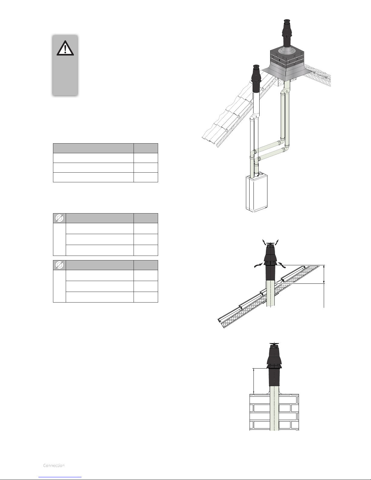
Assembly of combi-pipe vertical terminal
► On a steep roof, install a vertical weather slate with scale at
the location of the terminal.
On a flat roof, a weather slate (flat roof) for a pipe (Ø126 mm)
must be installed.
► Disassemble the manifold from the combi-pipe wall terminal.
► Slide the combi-pipe wall terminal
from the outside to the inside:
With a steep roof, through the vertical weather slate with scale.
With a flat roof, through the weather slate.
► Install the manifold from the combi-pipe wall terminal and
secure this with a panel screw or blind rivet.
IMPORTANT
► If the Intergas combi-pipe vertical
terminal cannot be used, the air supply
duct and flue must be implemented
separately.
► The individual flue pipe (Ø80) and/
or the internal pipe of the combi-pipe
wall terminal / extension pipe must be
constructed of stainless steel or PP T120.
► Concentric
Air supply duct and combustible gas exhaust pipe, excluding
the length of the combi-pipe wall terminal.
6.8.3 Roof terminal with combi-pipe vertical
terminal and twin-pipe vertical terminal C33
► Intergas combi-pipe vertical terminal
Boiler C33
Ø60/100
Intergas Xtreme 24 11 m
Intergas Xtreme 30 10 m
Intergas Xtreme 36 10 m
Boiler C33
Ø80/125
Intergas Xtreme 24 29 m
Intergas Xtreme 30 29 m
Intergas v vvvv 29 m
min. 300
min. 300
Page 35
35
IMPORTANT
► The air supply duct in the façade must
have an Intergas intake grille (item no
926187).
► The individual flue pipe (Ø80) must be
constructed of stainless steel or plastic
PP T120.
min. 500
Allowed pipeline length
Air supply duct and flue pipe, including the length of the
terminal.
Boiler Length
Intergas Xtreme 24 100 m
Intergas Xtreme 30 85 m
Intergas Xtreme 36 80 m
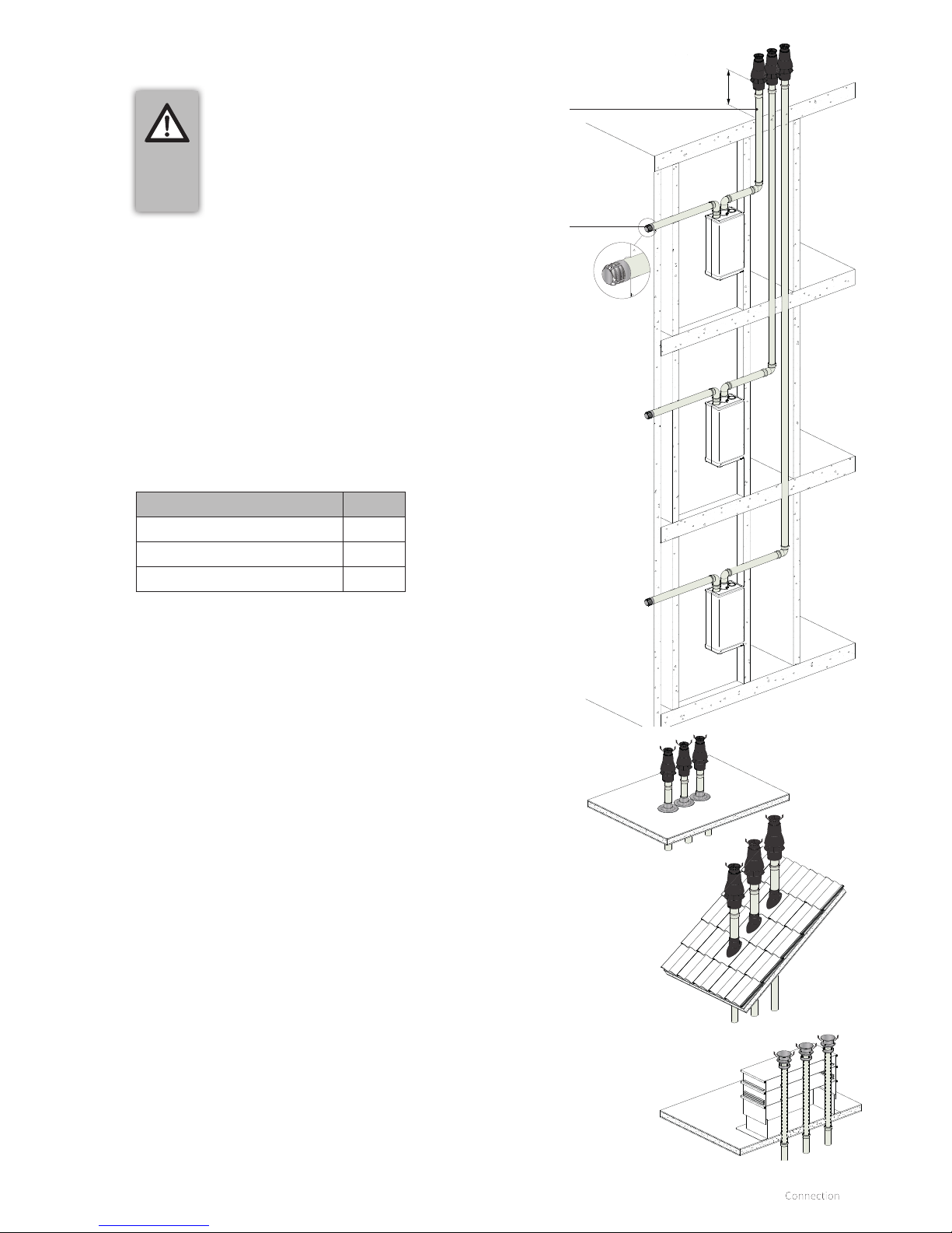
Assembly of vertical flue terminal
► On a steep roof, install a weather slate
with scale at the location of the terminal.
On a flat roof, install a weather slate for a double-walled
terminal Ø80 mm (diameter Ø96 mm).
► Slide the double-walled terminal from the
outside to the inside through the roof terminal.
The terminal must be at least 500mm above the roof
surface.
Assembly of horizontal air supply duct
► The air supply can be made in an arbitrary location in the
façade.
► At the location of the supply, make an opening of Ø90 mm.
► Shorten the air supply duct pipe to the desired length out of
the wall.
► Install the Intergas intake grille and attach this to the pipe.
► Slide the air supply duct pipe in the opening and cover the
opening, if necessary, with a rosette.
► Install the air supply duct, at the location of the façade
terminal, to the exterior at an angle directed outside to
prevent rain entering.
6.8.4 Roof terminal and air supply duct from the
façade C53
► Flue through a prefab chimney or through a double-walled
roof terminal Ø80 mm with pulling exhaust cap.
The prefab chimney must have flue openings of at least
150cm2 per connected boiler and must satisfy the indicated
minimum measurements. The supplier of the prefab chimney
must guarantee the correct operation of the chimney in terms
of wind exposure, ice formation, rain entering, recirculation etc.
Intergas intake grille
item no 926187
Flue
Page 36
36
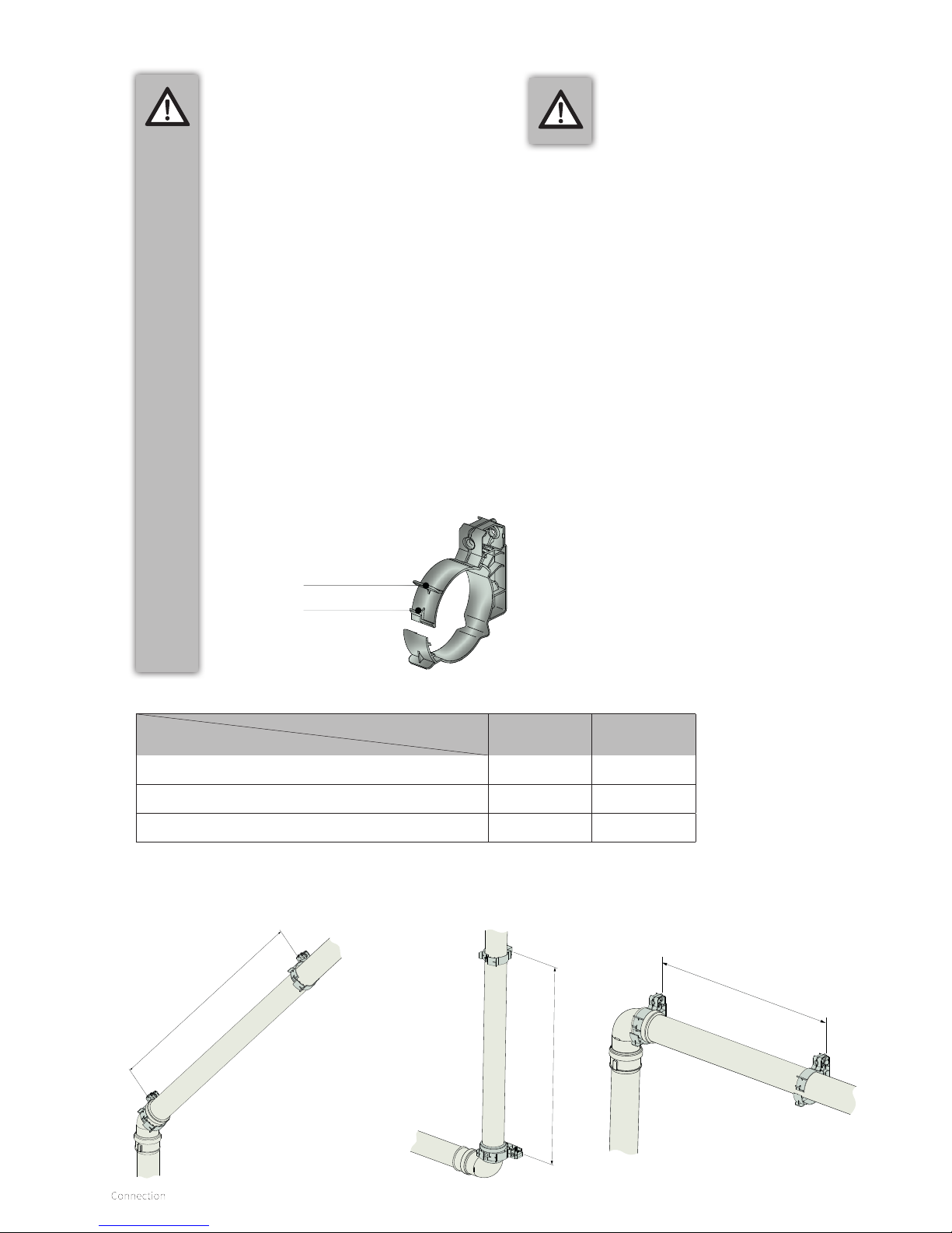
6.8.5 Clamping the flue system (parallel and concentric)
IMPORTANT
► These regulations are typical for both
concentric and parallel flue systems.
► The flue system must be secured to a
solid structure.
► The flue system should have a continuous
fall back to the boiler (1.5° to 3°).
► Only use accompanying brackets.
► Every elbow must be secured by using
the bracket.
Exception at connecting on boiler:
If the lenght of the pipes before and aer
the first elbow, are no more than 250
mm, the second element aer the first
elbow has to contain a bracket.
Note: The bracket must be positioned on
the elbow!
► Every extension must be secured per
metre with a bracket.
This bracket must not be clamped
around the pipe ensuring free movement
of the pipe.
► Make sure bracket is locked into the
correct position depending on the
position of the bracket on the pipe or
elbow:
max. 1000 mm
max. 2000 mm
max. 1000 mm
Fixation bracket on pipe
Fixation bracket on elbow
IMPORTANT
► Do not mix any components,
materials or ways of coupling
from dierent manufacturers.
Orientation
Flue system
Horizontal/
non-vertical
Vertical
Stainless steel 1000 mm 2000 mm
Safe-PP 1000 mm 2000 mm
Concentric 1000 mm 2000 mm
► Distribute the length between brackets evenly.
► Each flue system has to contain at least 1 bracket.
► The distance between the boiler and the first bracket may not be more than 500 mm.
Maximum distance between brackets
Page 37
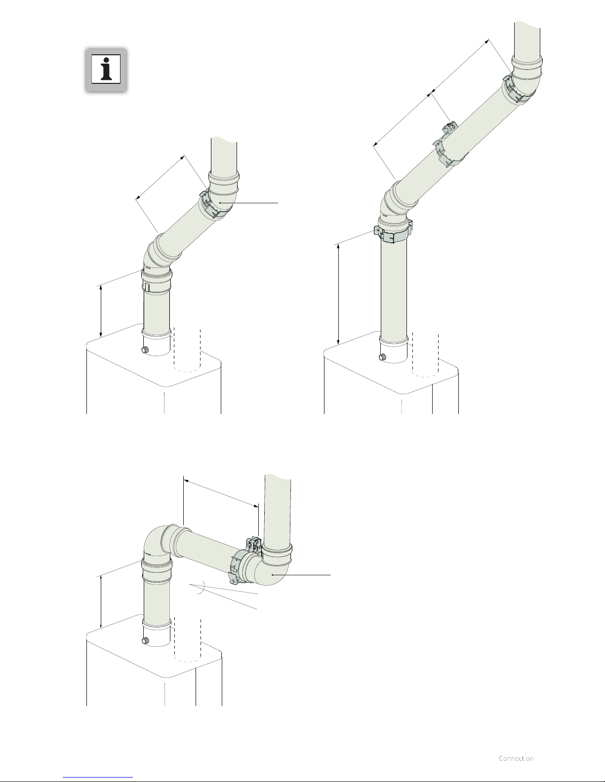
37
COMMENT
► Shown examples are typical for
both parallel and concentric
clamping.
max. 250 mm
max. 1000 mm
max. 1000 mm
max. 250 mm
max. 250 mm
max. 250 mm
max. 500 mm
min. 3° (or 50mm/m)
Second element aer first elbow
Second element
aer first elbow
Page 38
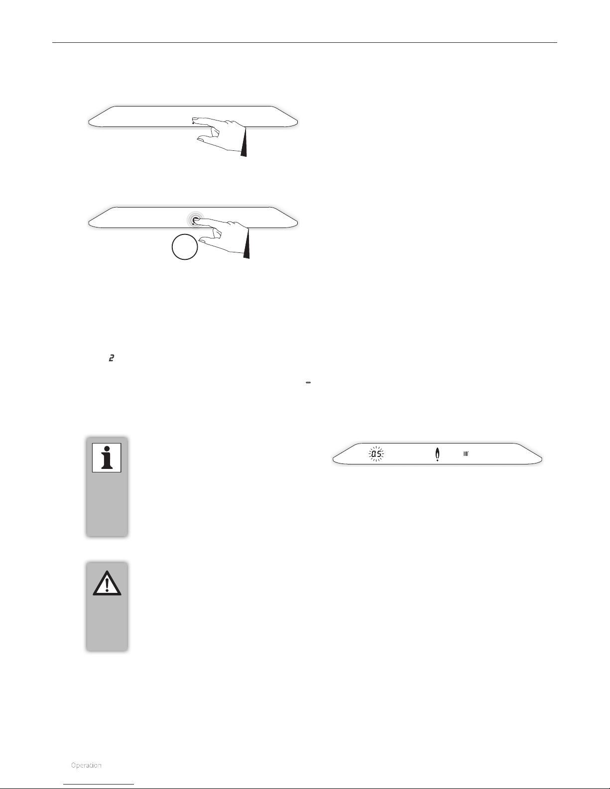
38
7.2.1 Filling and venting central heating system
7.2 Preparation activities
7.1 Using the control panel
► Connect to 3 amp fused spur.
► Connect the appliance to mains
A 2 may briefly appear on the right display; this means that
the connected sensors are being inspected. Then the boiler
enters the switched-o setting, characterised by a line – on
the right display and the central heating system pressure on
the le display.
7 OPERATION
► When the central heating pressure is
lower than 0.5bar, this will be shown
by a flashing display (if the boiler is
in central heating demand) and the
capacity will be reduced as a signal
function to the resident.
► Below 0.2bar central heating pressure,
central heating demand will no longer be
met.
WARNING
► If an additive is added to the central
heating water, this must be suitable
for the materials used in the boiler,
such as copper, brass, steel, stainless
steel, plastic and rubber. The additive
must preferably have a KIWA-ATA-Atest
certification.
Tapping
Touching and holding for 2 seconds
2sec
Central heating pressure is too low.
Page 39
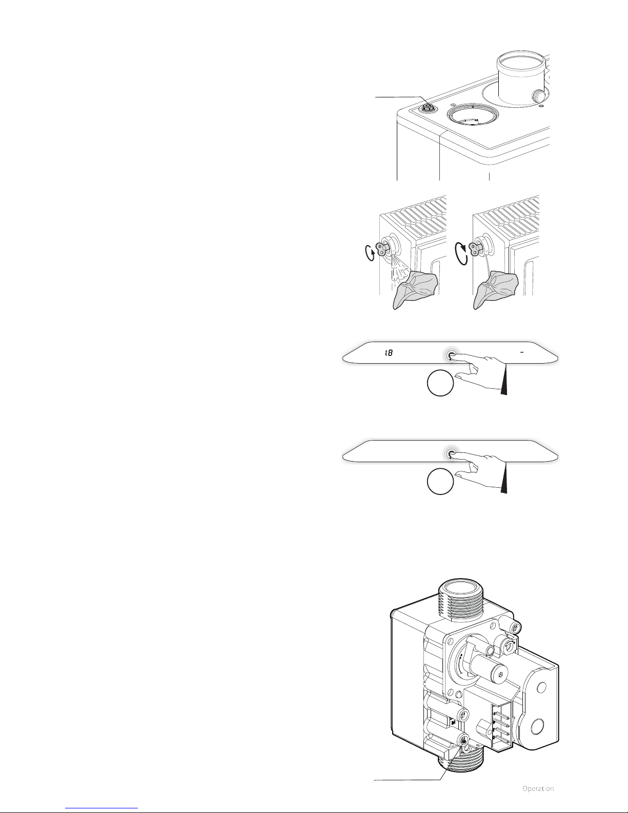
39
► Connect the filling loop and fill the installation with clean
drinking water to a maximum pressure of 1-2 bar in the case
of a cold installation (Indicated on le display.)
► Bleed the appliance with the manual bleed screw.
► Bleed the air in the installation with the manual bleed
screws on the radiators.
► Top up the CH installation if the pressure has dropped too
far as a result of the air bleeding.
► Check all couplings for leakage.
► Switch on the boiler by touching the control panel just
above the power LED and holding this for 2 seconds.
► Put the boiler in operation using the room thermostat or
Service company (see §8.1.5) and check the operation.
Switch on boiler
2sec
Switch o boiler
2sec
Manual air vent
7.2.2 Domestic hot tap water facility
► Open the mains tap to bring the domestic hot water section
under pressure.
► Vent the changer and the piping system
by opening a domestic hot water tap.
Leave the tap open until all air has disappeared from the
system. Close the tap again.
► Check all connections for leakage.
► Vent the gas piping with the inlet pressure measurement
nipple on the gas valve.
► Check all connections for leakage.
► Check the inlet pressure and possibly the gas-air control;
see §8.9.
7.2.3 Gas supply
Inlet pressure
measurement nipple
Page 40
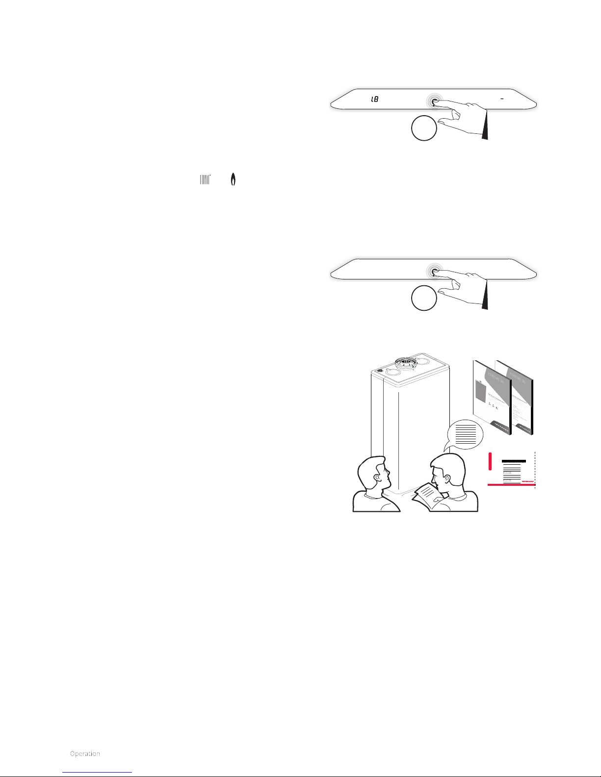
40
Garantiebewijs Intergas HR-ketel
Datum installatie:
Volgens geldende voorschriften
geïnstalleerd door:
Naam installateur:
Adres:
Postcode:
Woonplaats:
Naam koper:
Adres:
Postcode:
Woonplaats:
Voor de ‘Garantiebepalingen
Intergas HR-ketels’ verwijzen
wij u naar onze website:
www.intergasverwarming.nl
of naar het bij uw HR-ketel
bijgevoegde installatievoorschrift.
Op uw verzoek sturen wij u
graag een exemplaar toe.
>>Betrouwbaar in warmte
Type/Serienr.
voor klant
12345678910
Aer the preparation activities have been performed and
completed, the boiler can be commissioned. Follow the
following procedure for this:
► Switch on the boiler by touching just above the power LED
and holding this for 2 seconds.
► Adjust the pump setting depending on the set maximum
capacity and the water-sided resistance of the system.
Increase the pump pressure and the pressure loss of the
boiler; see §8.6.
► Set the temperature of the room thermostat higher than
the room temperature. The boiler is now starting central
heating demand. Symbols
and light up.
► Heat up the system.
► Check whether the set maximum central heating output
is in agreement with the desired value. If necessary, the
maximum central heating output can be adjusted; see §8.3
(parameter P010) and §8.5.
► Check whether the set minimum and maximum values of
the pump performance have been set correctly; see §8.3.
► Switch o the boiler by touching just above the power LED
and holding this for 2 seconds.
► Vent the system aer cooling (top o as needed; see
§7.2.1).
► Now switch on the boiler again by touching just above the
power LED and holding this for 2 seconds.
► Check the heating and the domestic hot water facility for
correct operation.
► Instruct the end user about filling and venting and the
operation of the heating and the domestic hot water facility.
► Give the operation instructions and guarantee card ‘for
customer’ to the end user.
7.3 Commissioning procedure
Switch on boiler
2sec
Switch o boiler
2sec
Comments
► The boiler has a burner controller which ignites the burner,
continuously monitors the flame and controls the fan and
the modulating pump with each heat demand of the heater
or the domestic hot water facility.
► With each heat demand, the circulation pump runs for
heating. The overrun can be set with parameter P033 (see
§8.3).
► The pump automatically runs once per 24 hours for 10
seconds to prevent becoming stuck. The automatic
switching on of the pump takes place 24 hours aer the last
heat demand.
► The pump does not run for the domestic hot water facility.
Page 41
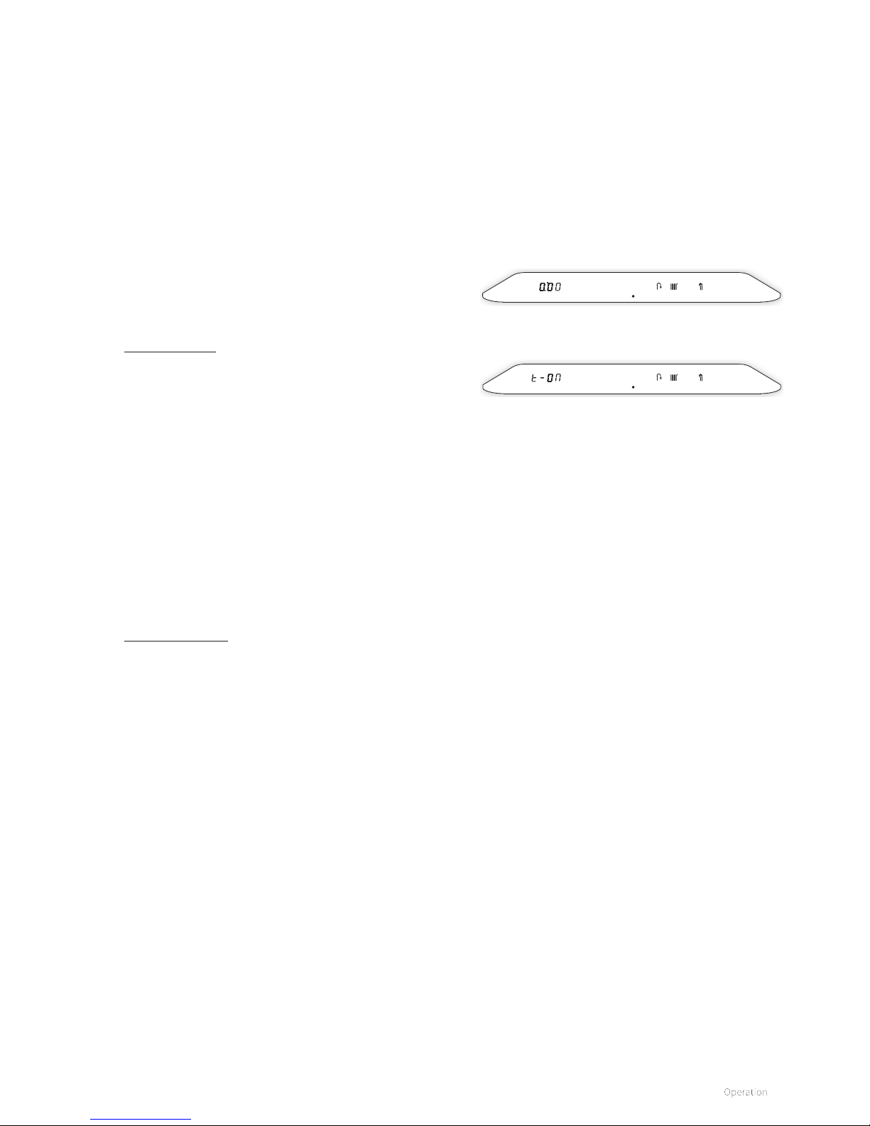
41
7.4 Clock function
Clock shown (P-on active)
T-on active
The boiler is equipped with a digital clock and oers the
possibility to program points in time for both CH operation and
DHW operation.
To activate the clock program the following parameters have to
be set:
For CH operation parameter P040 = 1
For DHW operation parameter P087 = 1
► In CH operation 6 points can be programmed to switch from
CH o or CH on.
► In DHW operation 4 points can be programmed to switch
the pre-heat function of the heat exchanger from on to
o. Also the pre-heat behavior of an external boiler can be
programmed in this mode.
Additionally the following special modes can be chosen:
In CH operation
► P-on (Program on):
The boiler will respond only on CH demands within the
chosen time blocks. If the clock program does not contain
any valid switching points, the boiler will respond on any
CH demand. The actual time is shown on the le display
indicating that the clock program is active.
► T-on (Temporary on):
The clock program will be temporary overruled. The
boiler will respond to every CH demand until the next "on"
switching point. On the le display t-ON will be shown.
► On (Continuous on):
The boiler will respond to every CH demand without any time
limit.
► O:
The boiler will not respond to any CH demand.
In DHW operation
► P-on (Program on):
The appliance's DHW comfort function is switched on
continuously within the chosen time blocks . In this mode the
heat exchanger will be kept on temperature to assure instant
delivery of DHW. If the clock program does not contain any
valid switching points, the heat exchanger will continuously
be kept on temperature.
► On (Continuous on):
The appliance's DHW comfort function is switched
on continuously. The heat exchanger will be kept on
temperature.
► Eco:
The appliance's DHW comfort function is self learning
within the chosen time blocks. The appliance will adapt
to the pattern of use of the hot water tap. As a result, the
temperature of the heat exchanger will not be maintained
during the night or in case of long absence. If the clock
program does not contain any valid switching points, the self
learning feature is maintained.
► O:
The temperature of the heat exchanger is not maintained, as
a result of which the delivery of hot domestic water takes a
little time. If there is no need for fast delivery of domestic hot
water, DHW comfort function can be switched o.
Page 42

42
CAREFUL
► Drain the boiler and the system if the
mains voltage has been interrupted and
there is a chance of freezing as a result.
7.5 Shutting down the boiler
► Switch o the boiler.
► Remove the plug from the wall socket.
► Turn o the gas valve under the boiler.
► Drain the boiler with the fill/drain tap.
► Drain the system at the lowest point.
► Close the mains tap for the water supply of the domestic
hot water.
► Drain the boiler by disconnecting the domestic hot water
connections under the boiler.
If an external boiler is installed (Parameter P001 = 1)
► P-on (Program on):
The external boiler will be kept on temperature within
the chosen time blocks . If the clock program does not
contain any valid switching points, the external boiler will
continuously be kept on temperature. The boiler can be
heated outside the chosen time blocks by means of an
OpenTherm demand or via the Incomfort app.
► On (Continuous on):
The external boiler will be constantly kept on temperature.
► Eco:
The external boiler is heated within the chosen time blocks
by means of an OpenTherm demand or via the Incomfort
app. If the clock program does not contain any valid
switching points, all heat demands will be answered.
► O:
The external boiler will not be kept on temperature.
Note
For setting and adjusting the clock and timer function see §8.2.
Page 43
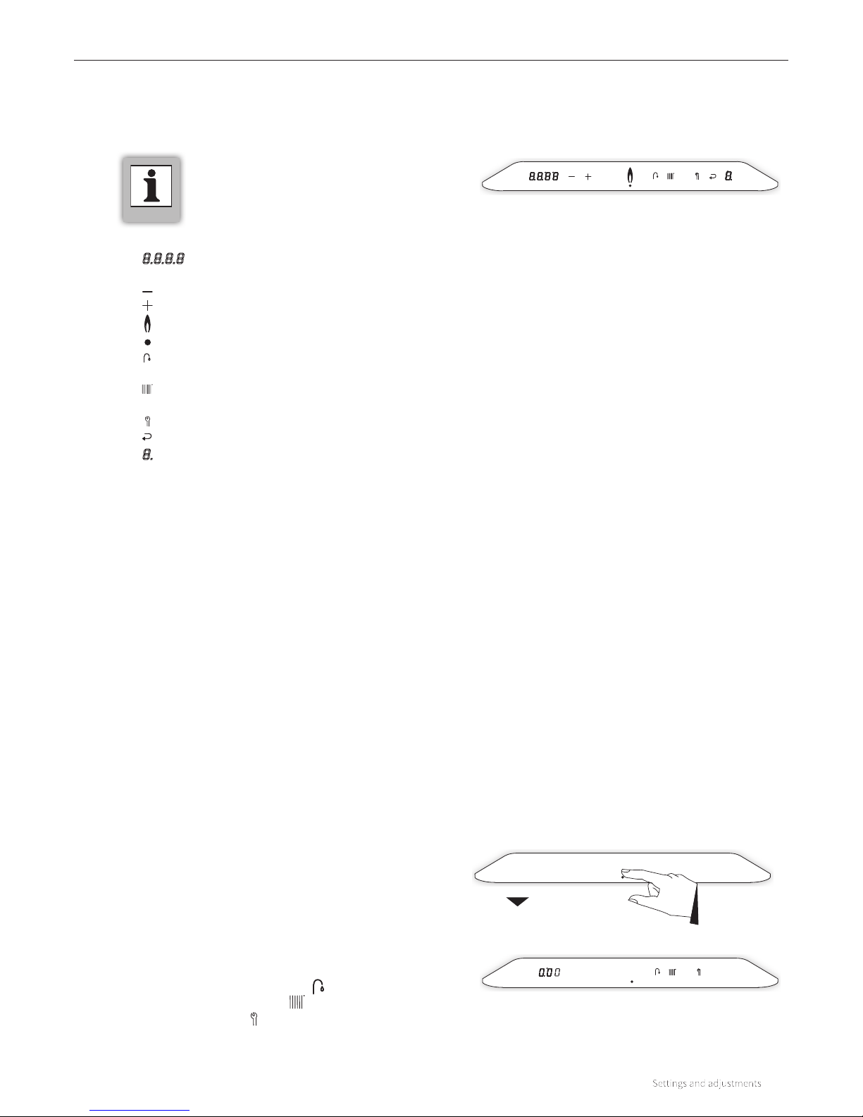
43
The functioning of the boiler can be influenced by the various
(parameter) settings in the burner controller. Based on a number
of specific menus, these settings can be made and modified
via the display. Some of the settings are only accessible aer
entering the installer’s code (see §8.1.5 and §8.3).
The main menu is accessible by tapping just above the power
LED. The main menu can be requested in a boiler that is
switched on as well as one that is switched o. If no button is
used in the main menu for 1 minute, the display returns to the
initial setting.
The following buttons will light up:
► The domestic hot water symbol
► The central heating symbol
► The Service symbol
Also, on the le display the clock time is shown.
The structure of the settings is built up from various menus that
are accessible via certain buttons (of button combinations).
The following menus are available:
► Main menu
Higherlevel menu from which all other menus are
accessible.
► Domestic hot water menu
Menu in which several domestic hot water-related settings
can be set and/or modified.
► Central heating menu
Menu in which several central heating-related settings can
be set and/or modified.
► RF menu
Menu in which RF room thermostats can be assigned to the
boiler.
► Service menu
Menu in which the test programs can be activated and
from which the (installer’s) parameters can be modified
(installer’s code required).
8 SETTINGS AND ADJUSTMENTS
► The boiler has a touch screen control panel.
Buttons will light up as soon as they are
operable and they will be extinguished when
they are no longer available.
8.1 Structure of the settings
8.1.1 Main menu
8
Main menu
Initial setting
Control panel with all options
► 8.8.8.8 : Le display / Desired temperature in °C /
Central heating pressure / Fault code / Time
► : - (Minus) button
► : + (Plus) button
►
: In operation (burner is switched on)
► : Power LED
► : Tap operation / tap comfort setting /
Temperature domestic hot water setting
► : Central heating demand / Adjusting
maximum central heating temperature
► : Service button
► : Enter button
► 8. : Right display / operational code
Page 44
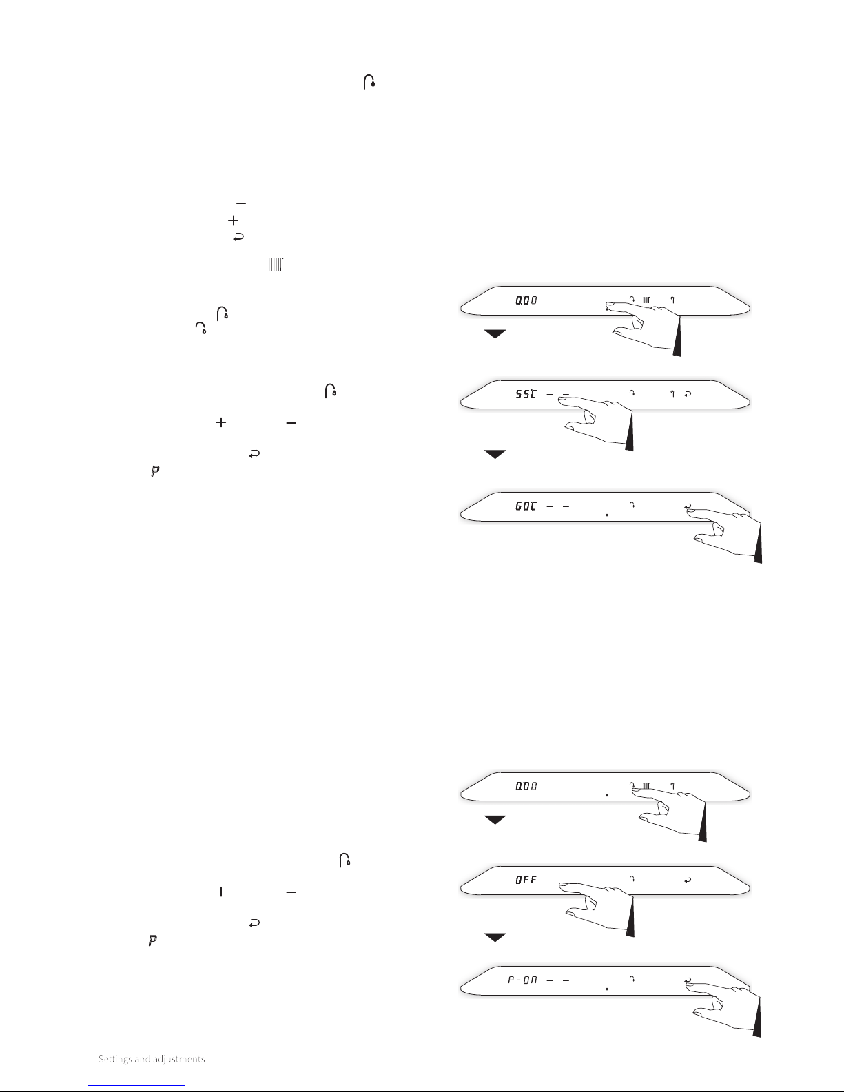
44
8.1.2 Domestic hot water menu
For the quick supply of domestic hot water, a DHW comfort
function has been built in. This has the following settings:
► P-On:
The DHW comfort function is switched on within the chosen
time blocks. The heat exchanger will maintain temperature
during these time blocks.
► On:
The DHW comfort function is continuously switched on. The
boiler always supplies domestic hot water immediately.
► Eco:
The DHW comfort function of the boiler is self learning. The
boiler will adapt itself to the pattern of use of domestic hot
water. This means that the heat exchanger will not maintain
temperature during the night or with long absences.
► O:
The heat exchanger is not kept warm, as a result of which
the supply of domestic hot water is somewhat delayed. If
there is no need for a quick supply of domestic hot water,
the DHW comfort function can be switched o.
Confirm
Main menu
Domestic hot
water menu
Tap comfort
The domestic hot water menu has 2 settings and is accessible
by tapping on the Domestic Hot Water symbol from the
main menu.
Via the domestic hot water menu:
► the domestic hot water temperature can be modified
► the DHW comfort function can be modified
The following buttons will light up:
► The Minus symbol
► The Plus symbol
► The Enter symbol
The Central Heating symbol will be extinguished.
The le display will light up and will display the current
domestic hot water temperature by tapping on the Domestic
Hot Water symbol . By tapping again on the Domestic Hot
Water symbol , it alternates between ‘modify domestic hot
water temperature’ and ‘modify DHW comfort function’.
To modify the domestic hot water temperature:
1. Tap the Domestic Hot Water button
. The set temperature
is shown on the le display.
2. Using the Plus and Minus buttons, set the desired
temperature (for example, 60°C).
3. Tap the Enter button
to confirm (or wait 30 seconds).
A
P appears on the right display (all other buttons are
extinguished), which means the setting has been stored.
4. The display returns to the main menu.
To modify the DHW comfort function:
1. Tap the Domestic Hot Water button 2x
. The set tap
comfort setting is shown on the le display.
2. Using the Plus and Minus buttons, set the desired tap
comfort setting (for example, P-On).
3. Tap the Enter button
to confirm (or wait 30 seconds).
A P appears on the right display (all other buttons are
extinguished), which means the setting has been stored.
4. The display returns to the main menu.
Main menu
Confirm
Domestic hot
water menu
Temperature
Page 45
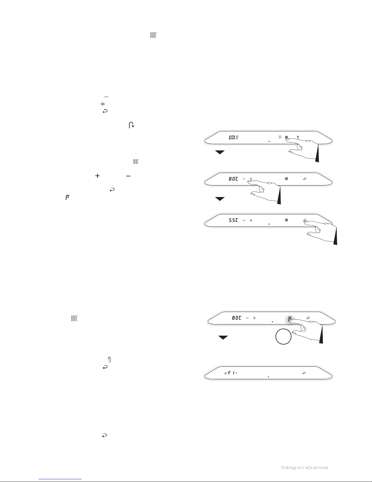
45
The central heating menu has 3 settings and is accessible
by tapping on the Central Heating symbol from the main
menu. Via the central heating menu:
► the maximum temperature of the central heating water can
be modified
► access to the RF menu can be obtained
► the timer function can be set
The following buttons will light up:
► The Minus symbol
► The Plus symbol
► The Enter symbol
The Domestic Hot Water symbol will be extinguished.
The Xtremeis standardly provided with a built-in transmitting/
receiving module, which makes the boiler suitable for wireless
communication with the Honeywell room thermostats
T87RF2025 Round RF and CMS927.
Assignment of the thermostat and additional settings can be
made via the RF menu.
The RF menu is accessible by touching the Central Heating
symbol
and holding it for 2 seconds. The following settings
can then be made:
► Assign RF thermostat
► Remove assignment between boiler and RF thermostat
The following buttons will light up:
► The Service symbol
► The Enter symbol
The le display will light up and, depending on the assignment
of the boiler, will show ‘RF1–’ or ‘RF1’.
RF1–:
Boiler and thermostat are not assigned.
RF1:
Boiler and thermostat are assigned.
Tap the Enter button
(or wait 1 minute) to save and return
to the main menu. By tapping just above the power LED, the
display returns to the initial setting and no settings are saved.
8.1.3 Central heating menu
8.1.4 RF menu
Central heating
menu
The le display will light up and the current temperature of the
central heating water will be displayed.
To modify the temperature of the central heating water:
1. Tap the Central Heating button
. The set temperature of
the central heating water is shown on the le display.
2. Using the Plus and Minus buttons, set the desired
temperature (for example, 55°C).
3. Tap the Enter button
to confirm (or wait 30 seconds).
A P appears on the right display (all other buttons are
extinguished), which means the setting has been stored.
4. The display returns to the main menu.
RF menu
Main menu
Confirm
Central heating
menu
2sec
Page 46
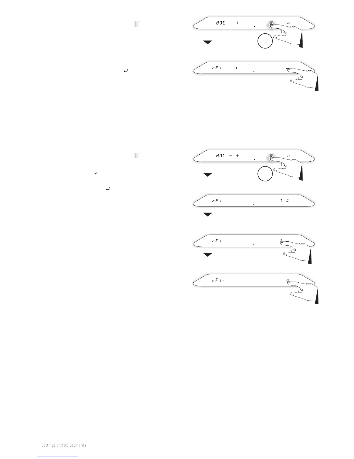
46
Delete assignment
Confirm
Confirm
RF menu
To modify an RF room thermostat:
1. Touch the Central Heating symbol and hold for 2
seconds.
2. The method of assignment is dependent on the type
of room thermostat and is described in the installation
manual and operation instructions of the wireless room
thermostat.
3. Aer a successful assignment, ‘RF1’ appears in the le
display. Tap the Enter symbol to save.
To remove an assignment:
1. Touch the Central Heating symbol
and hold for 2
seconds.
2. ‘RF1’ appears in the le display.
3. Tap the Service button to remove the assignment.
4. ‘RF1–’ appears in the le display.
5. Tap the Enter symbol to confirm the removal and return
to the main menu.
6. Make a new assignment if desired.
Central heating
menu
2sec
Central heating
menu
2sec
Page 47
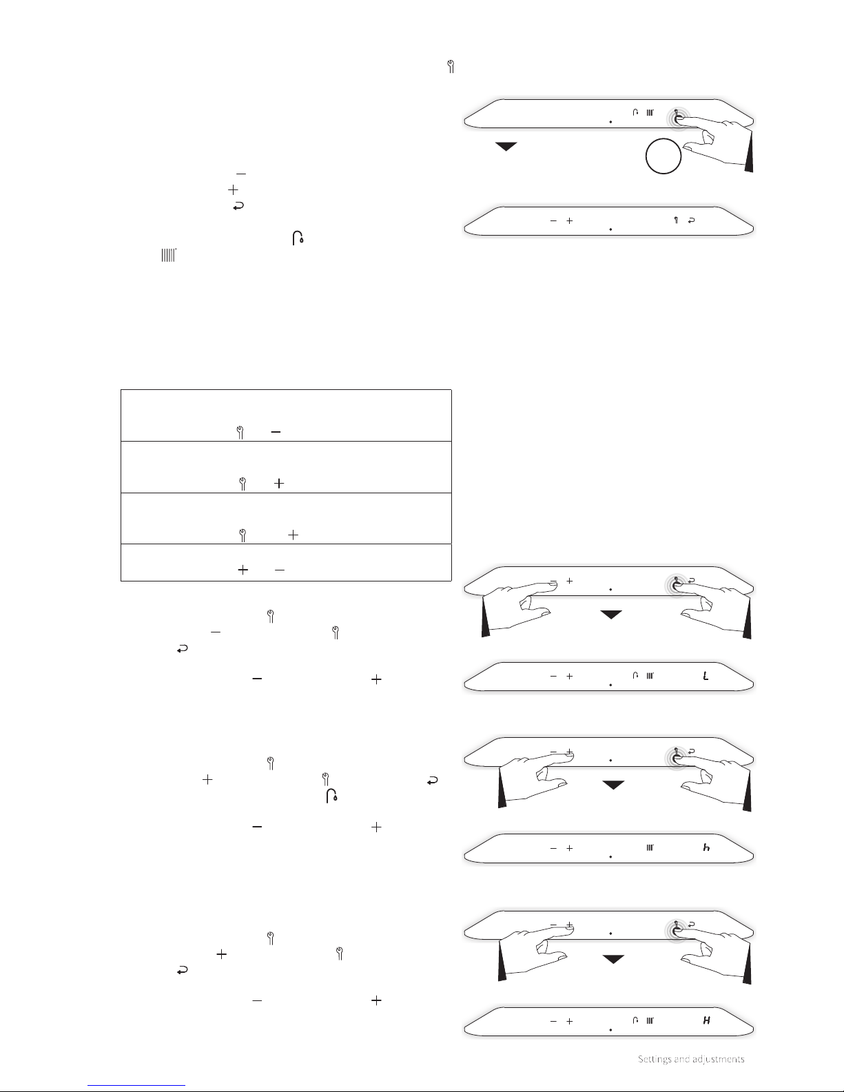
47
The service menu is accessible by touching the Service button
from the menu and holding it for 2 seconds.
Via the service menu:
► the test programs can be activated
► access to the (installer’s) parameters can be obtained
The following buttons will light up:
► The Minus symbol
► The Plus symbol
► The Enter symbol
The Domestic Hot Water symbol and the Central Heating
symbol will be extinguished.
8.1.5 Service menu
Service menu
Main menu
Service menu
Test program ‘L’
Test program ‘h’
Test program ‘H’
Service menu
Service menu
Test programs
A feature has been installed in the burner controller to bring
the boiler in a test mode. By activating a test program, the
boiler will operate with a fixed fan speed without the control
functions intervening. However, the safety functions remain
active.
The following test programs are available:
Program ‘L’
Burner on with minimum DHW capacity.
Button combination and
Program ‘h’
Burner on with set maximum central heating output.
Button combination and
Program ‘H’
Burner on with maximum capacity.
Button combination and 2x
Switching o test program
Button combination and
To activate the ‘L’ test program:
1. Hold the Service button and at the same time tap the
Minus button . The Service button and the Enter
button will be extinguished. An ‘L’ will appear on the
right display.
2. Tap the Minus button and the Plus button at the same
time to terminate the program.
To activate the ‘h’ test program:
1. Hold the Service button
and at the same time tap the
Plus button . The Service button , the Enter button
and the Domestic Hot Water button
will be extinguished.
An ‘h’ will appear on the right display.
2. Tap the Minus button and the Plus button at the same
time to terminate the program.
To activate the ‘H’ test program:
1. Hold the Service button
and at the same time tap the
Plus button 2x . The Service button and the Enter
button will be extinguished. An ‘H’ will appear on the
right display.
2. Tap the Minus button and the Plus button at the same
time to terminate the program.
2sec
Page 48
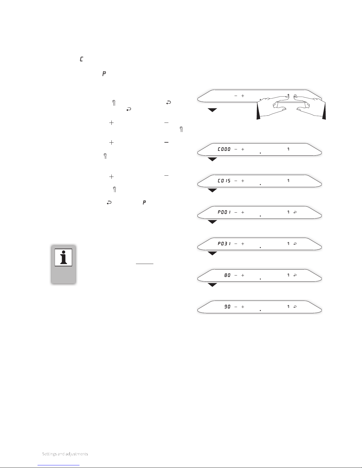
48
Service menu
(Installer’s) parameters
The (installer’s) parameters of the burner controller are factoryset according to the table in §8.3.
These parameters can only be modified using the installer’s
code.
The installer’s code is shown on the le display and is preceded
by the letter C.
The parameters are also shown on the le display and are
preceded by the letter P.
To modify a parameter:
(for example, modify parameter P031 from 80 to 90)
1.
Tap the Service button and the Enter button at the
same time. The Enter button
is extinguished and all
other buttons remain on. ‘C000’ appears in the le display.
2. Using the Plus button and the Minus button , set the
installer’s code (C015) and tap on the Service button .
Parameter ‘P001’ will now be shown on the le display.
3. Using the Plus button and the Minus button , set the
desired parameter (in this example, ‘P031’) and tap on
the Service button . The current value of the relevant
parameter will be shown on the le display (in this example,
‘80’).
4. Using the Plus button and the Minus button , set the
desired value of the parameter (in this example, ‘90’).
5. Tap the Service button . Repeat Steps 3 and 4 to set any
additional parameters.
6. Tap the Enter button
to confirm. A P appears on the right
display (all other buttons are extinguished), which means
the settings have been stored.
7. The display returns to the initial setting and is ready for any
heat demand.
► By tapping just above the power LED during
a parameter modification, the modification
procedure is ended without the parameter
modification being saved. The display returns
to the initial setting and is ready for any heat
demand.
Page 49
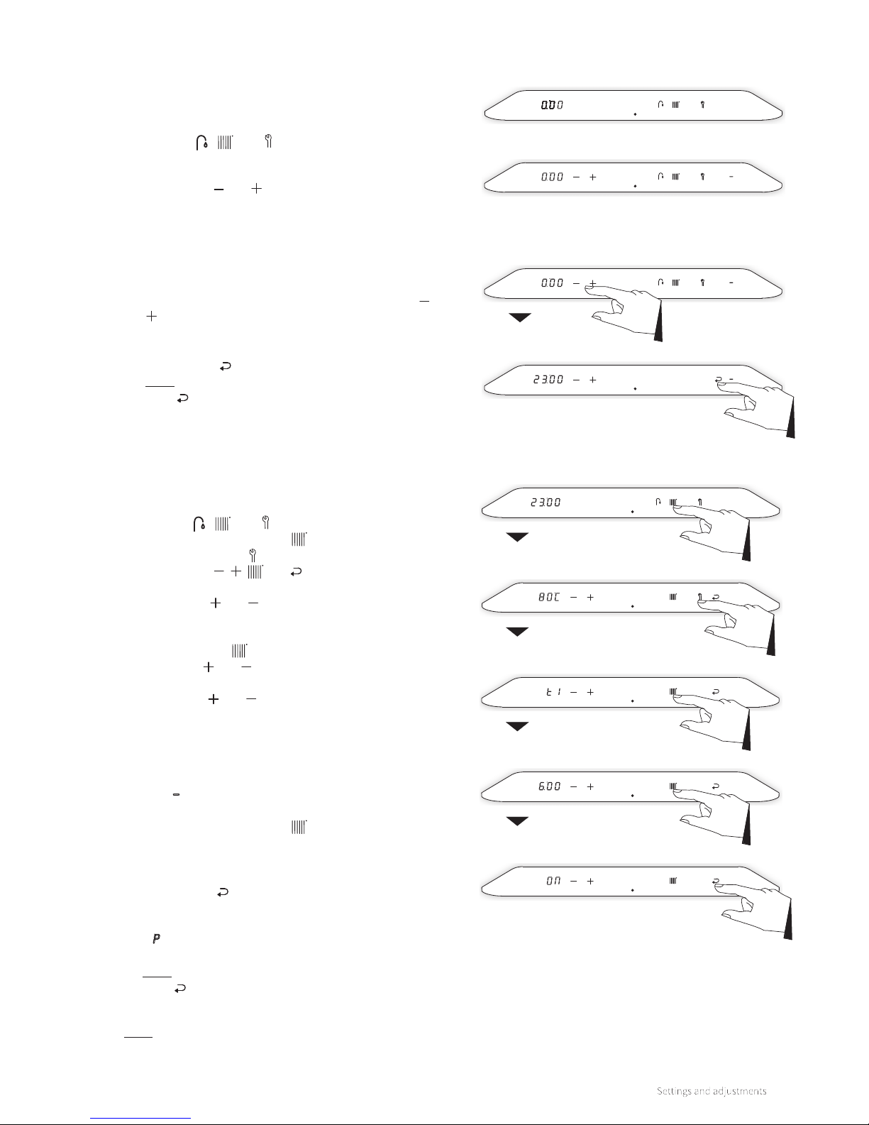
49
Show actual time
8.2.1 Setting the clock program on CH operation
Setting the clock
8.2 Setting and adjusting the clock functions
Clock shown (boiler standby)
Clock shown (boiler switched o)
► From a boiler that is in standby or in operational mode tap
just above the power LED to access the main menu (also
see §8.1.1). The actual time is shown in the le display. The
symbols , and also light up.
► If the boiler is switched o when accessing the main menu
the symbols and will light up as well.
► Check if the boiler is switched o or otherwise switch it o
by touching just above the power LED and holding this for 2
seconds.
► Tap just above the power LED to access the main menu.
Adjust the clock to the correct time by pressing the and
buttons.
Note: Holding the button for more than 1 second will make
the clock run fast.
► Tap the Enter button to confirm.
Note: By tapping just above the power LED instead of the
Enter button the display returns to the main menu
without saving any changes.
► From a boiler that is in standby or in operational mode tap
just above the power LED to access the main menu. The
symbols , and light up.
► Tap on the Central Heating button.
► Tap on the Service button.
► The symbols , , and are shown. Also the first
switching period "t1" appears on the le display.
► Tapping the and buttons will change between the 6
dierent on/o switching periods.
► Choose a switching period (for instance "t1") and tap on the
Central Heating button.
► Tap on the and buttons to set the time and tap the
Central Heating button again to set the desired action by
tapping the and buttons.
The actions to be set are as follows:
► On: Start of period CH on. From this switching point
requests for heat demands will be answered.
► O: End of period CH o. From this switching point
requests for heat demands will not be answered.
► – : No action. This switching point will have no eect
on requests for heat demands.
► Tap on the Central Heating button to select the
next switching period. Set the switching time and the
corresponding action and repeat this, if needed, for all 6
switching periods.
► Tap the Enter button to confirm. The switching times and
actions will be saved in the boiler controller. Aer 2 minutes
of inactivity changes made will also be saved.
A P appears in the right display and the display returns to
the Central Heating menu.
Note: By tapping just above the power LED instead of the
Enter button the display returns to the Central Heating
menu without storing any changes.
Confirm
Switch moment 1
Switch point t1
Action moment t1
Main menu
Main menu
Central heating menu
Note
► Switching points and actions may be set in random order.
There is no need to set times and actions chronologically.
Page 50
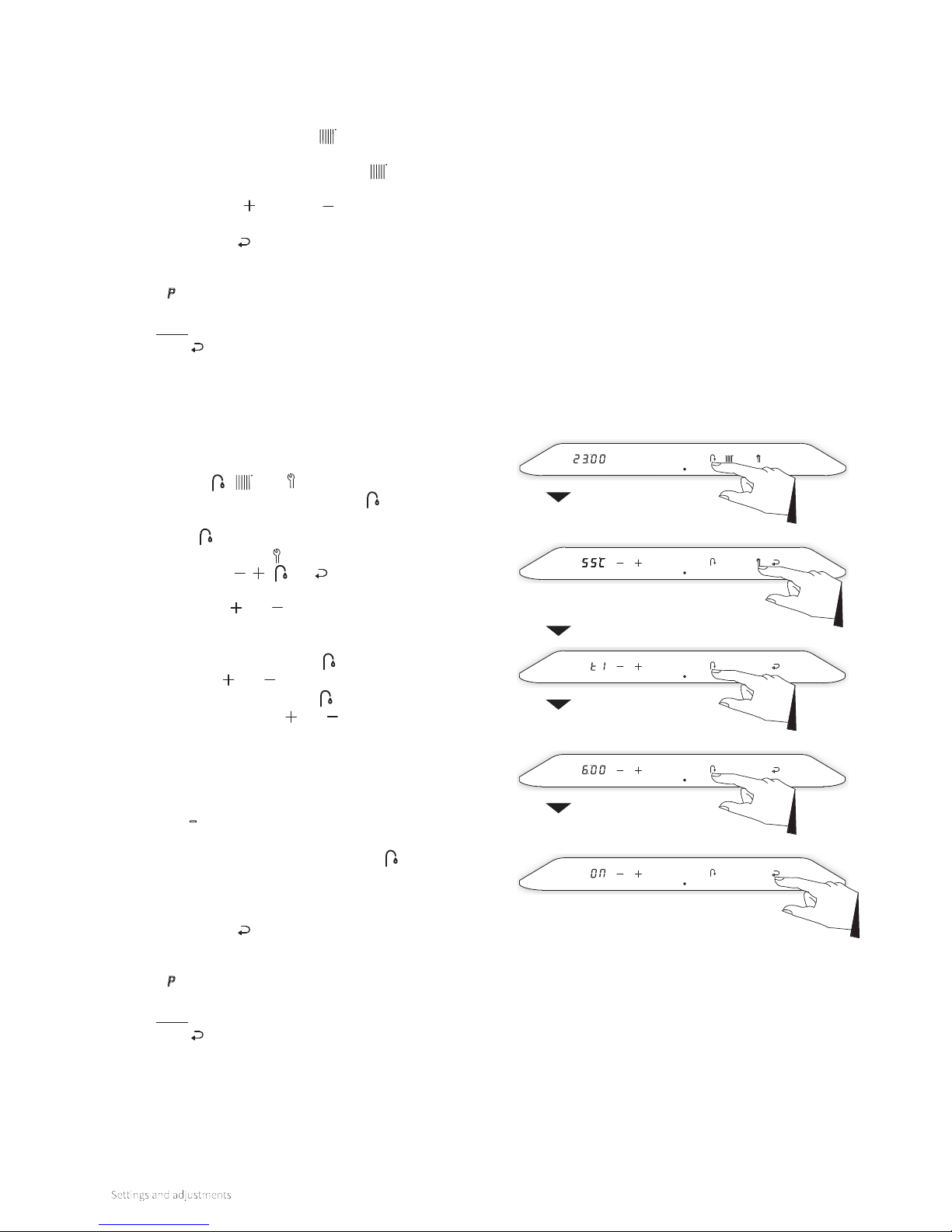
50
8.2.2 Setting the clock program on DHW operation
► From a boiler that is in standby or in operational mode tap
just above the power LED to access the main menu. The
symbols , and light up.
► Tap the Domestic Hot Water button
. The set temperature
is shown on the le display. Tap the Domestic Hot Water
button
again to switch to the clock program setting
► Tap on the Service button.
► The symbols , , and are shown. Also the first
switching period "t1" appears on the le display.
► Tapping the and buttons will change between the 4
dierent on/o switching periods.
► Choose a switching period (for instance "t1") and tap on the
Domestic Hot Water button
.
► Tap on the and buttons to set the time and tap the
Domestic Hot Water button
again to set the desired
action by tapping the and buttons.
The actions to be set are as follows:
► On: Start of period DHW on. From this switching point
the heat exchanger will be kept on temperature.
► O: End of period DHW o. From this switching point
the heat exchanger will not be kept on temperature.
► – : No action. This switching point will have no eect
on maintaining the heat exchanger's temperature.
► Tap on the Domestic Hot Water button
to select the
next switching period. Set the switching time and the
corresponding action and repeat this, if needed, for all 4
switching periods.
► Tap the Enter button to confirm. The switching times and
actions will be saved in the boiler controller. Aer 2 minutes
of inactivity changes made will also be saved.
A P appears in the right display and the display returns to
the Central Heating menu.
Note: By tapping just above the power LED instead of the
Enter button the display returns to the Central Heating
menu without storing any changes.
To apply the clock program
► From a boiler that is in standby or in operational mode tap
just above the power LED to access the main menu (also
see §8.1.1).
► Tap on the Central Heating button. The current
temperature of the central heating water is displayed in the
le display. Tap the Central Heating button again to
switch to the clock program setting.
► Using the Plus and Minus buttons, set the desired
program setting (P-on, T-on, On or O).
► Tap the Enter button to confirm. The chosen program
setting will be saved in the boiler controller. Aer 2 minutes
of inactivity changes made will also be saved.
A P appears in the right display and the display returns to
the Central Heating menu.
Note: By tapping just above the power LED instead of the
Enter button the display returns to the Central Heating
menu without storing any changes.
Main menu
Domestic hot
water menu
Temperature
Switch moment 1
Switch point t1
Action moment t1
Page 51

51
To apply the clock program
► From a boiler that is in standby or in operational mode tap
just above the power LED to access the main menu (also
see §8.1.1).
► Tap on the Domestic Hot Water button
. The current
temperature of the central heating water is displayed in the
le display. Tap the Domestic Hot Water button
again to
switch to the clock program setting.
► Using the Plus and Minus buttons, set the desired
program setting (P-on, On, Eco or O).
► Tap the Enter button to confirm. The chosen program
setting will be saved in the boiler controller. Aer 2 minutes
of inactivity changes made will also be saved.
A P appears in the right display and the display returns to
the Central Heating menu.
Note: By tapping just above the power LED instead of the
Enter button the display returns to the Domestic Hot
Water menu without storing any changes.
Page 52
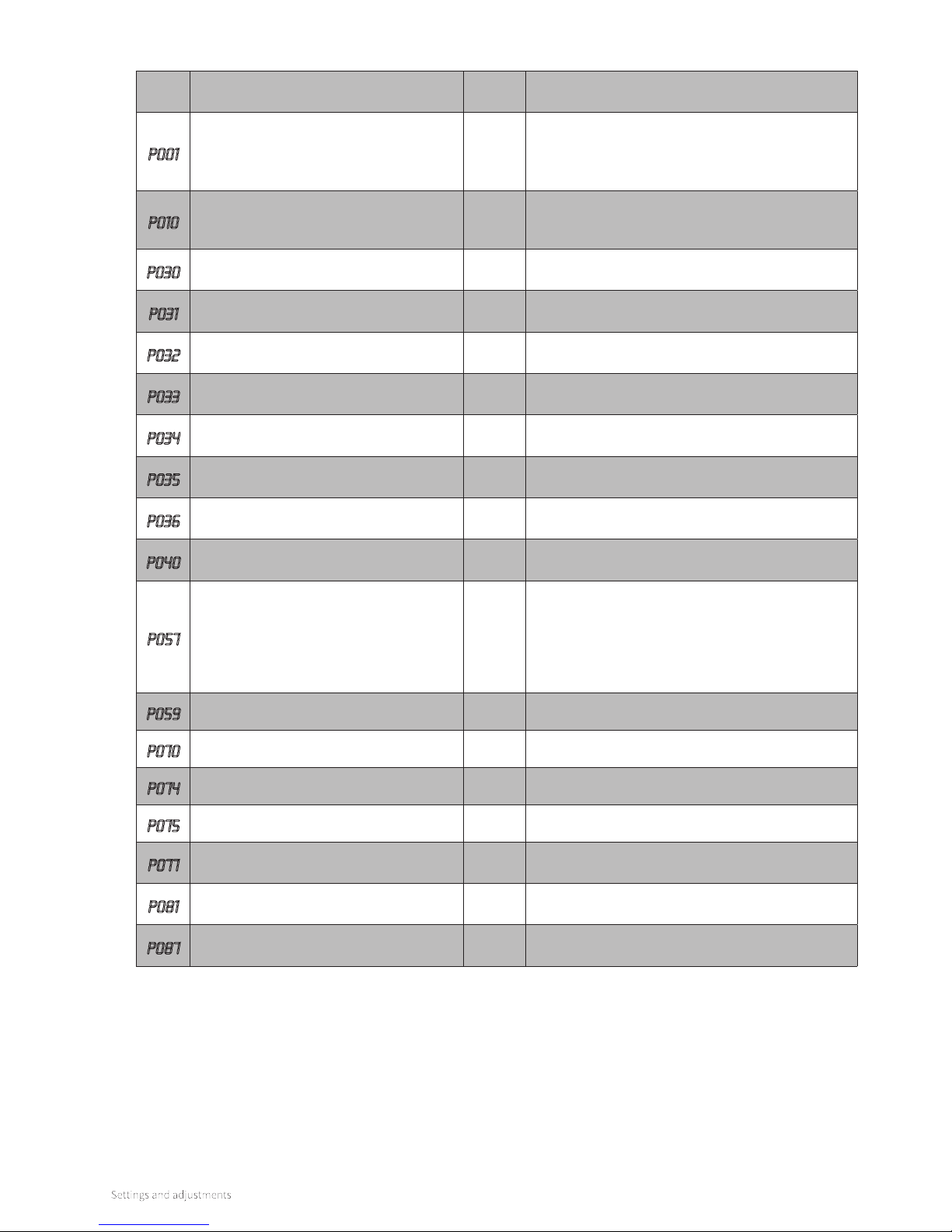
52
Para
metre
Setting
Set
value Description/Setting range
P001
System type 0
0 = Xtreme Kombi
1 = Xtreme Solo + Boiler
2 = Xtreme Tap
3 = Xtreme Solo
P010
Set maximum central heating output
75
------100
75 = Xtreme 36
100 = Xtreme 24 / Xtreme 30
25% to 100% (see §8.5)
P030
Central heating pump setting 0
0 = overrun active
1 = continuous
1
P031
Maximum capacity of modulating central
heating pump
65 Set value of parameter P032 to 100%
P032
Minimum capacity of modulating central
heating pump
35 15% to set value of parameter P031
P033
Central heating pump overrun aer central
heating demand
1 0 to 15 minutes
P034
Central heating pump overrun aer boiler
operation
1 0 to 15 minutes (n/a for Kombi boiler)
P035
Step modulation 1
0 = o
1 = on
P036
Anti-pendulum time central heating 5
Minimum switch-o time for boiler water temperature
0 to 15 minutes
p040
Activate clock program CH operation 0
0 = inactive
1 = active
P057
Response of OpenTherm room thermostat 1
0 = do not respond to heat demand if requested
temperature is lower than 30°C
1 = respond to heat demand with minimum flow
temperature limited at 30°C
2 = respond to heat demand with maximum set flow
temperature (on/o function)
P059
Maximum setting value of flow temperature 80 10°C to 90°C
P070
Set maximum DHW capacity 100 20% to 100%
P074
Number ECO days 7 0 to 10 days
P075
Control temperature during boiler operation 80 60°C to 90°C
P077
Waiting time central heating demand aer
DHW operation
0 to 15 minutes
P081
Setting of three-way valve or electric shuto valve
0
0 = powered during central heating demand
1 = powered during DHW operation
p087
Activate clock program DHW operation 0
0 = inactive
1 = active
8.3 Parameters
1
DHW comfort function o.
Page 53
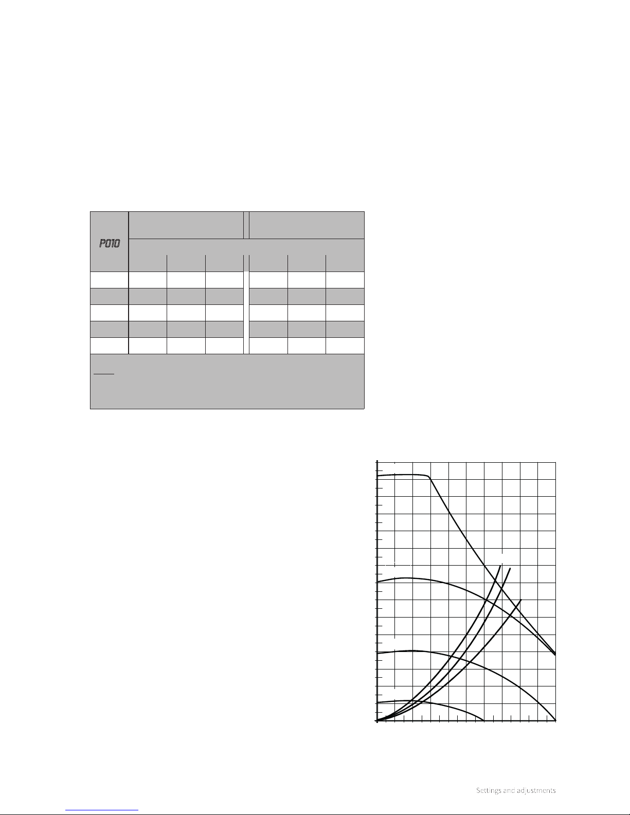
53
8.5 Adjusting maximum central heating output
8.6 Adjusting pump capacity
The maximum central heating output is factory-set. If more
or less output is needed for the central heating system, the
maximum central heating output can be modified with
parameter P010. See the table below:
Setting central heating output.
The Xtremehas a modulating pump that modulates that
modulates based on the central heating output provided. The
minimum and maximum capacity of the pump can be adjusted
with the parameters P031 and P032. Also see §8.3.
The set value of parameter P031 (max. pump setting) is the
percentage of the maximum pump capacity and is linked to
the set maximum central heating output which is set with
parameter P010.
The set value of parameter P032 (min. pump setting) is linked
to the minimum central heating output.
The pump capacity must be set such that the temperature
dierence between the supply and return fits with the system.
If the central heating load modulates between the minimum
and maximum value, the pump capacity will modulate along
proportionately.
Pressure loss graph boiler central heating side
A. Xtreme 24
B. Xtreme 30
C. Xtreme 36
8.4 Switching DHW comfort function on and o
It is possible to switch on and o the DHW comfort function
from an OpenTherm room thermostat (provided the
thermostat supports this function). To do this, the boiler must
be set at the ‘eco’ setting and the parameter P074 must be
set to 0. The self-learning character of the control is therefore
switched o.
P010
Desired central heating
output in kW (approx.)
Minimum flow
quantity (l/h)
Xtreme
24 30 36 24 30 36
100 13,8 19,4 25,7 396 557 738
75 10,6 14,6 19,3 304 419 553
50 7,3 9,8 12,8 210 281 369
35 5,4 7,0 9,0 155 201 258
25 - 5,1 6,4 - 146 184
Note:
The output during combustion will be slowly increased and decreased
as soon as the set flow temperature is achieved (modulation on T
flow
).
25%
50%
75%
100%
1
0
2
3
4
5
6
7
H/M
l/hr
0 500 1000 1500 2000
C
B
A
Page 54
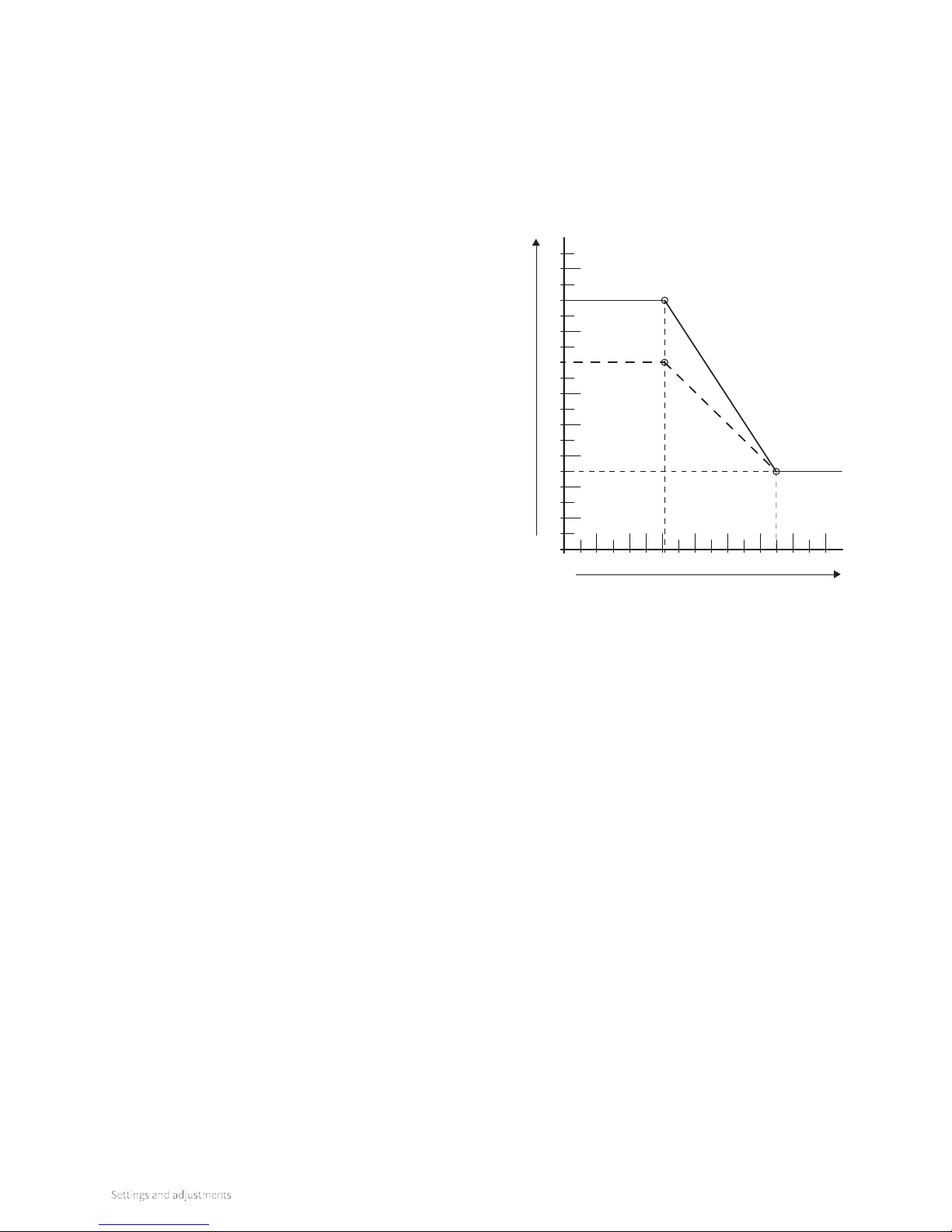
54
8.7 Weather-dependent control
When an outdoor sensor is connected, the flow temperature
will be automatically controlled according to the set heating
line, depending on the outside temperature.
The weather-dependent control functions solely with an
on/o room thermostat. When using an OpenTherm room
thermostat, the outside temperature will be relayed, but the
heating line of the central heating boiler will not be active.
Heating line
X: T outside in °C
Y: T flow in °C
A. Factory setting
(T
max
CH = 80°C, T
min
CH = 25°C, T
min
out = -9°C, T
max
out = 25°C)
B. Example
(T
max
CH = 60°C, T
min
CH = 25°C, T
min
out = -9°C, T
max
out = 25°C)
-30 -20 -10 0
0
10
20
30
40
50
60
70
80
90
10 20 30
AA
B
Tmax.
Tmin.
X
Y
Page 55
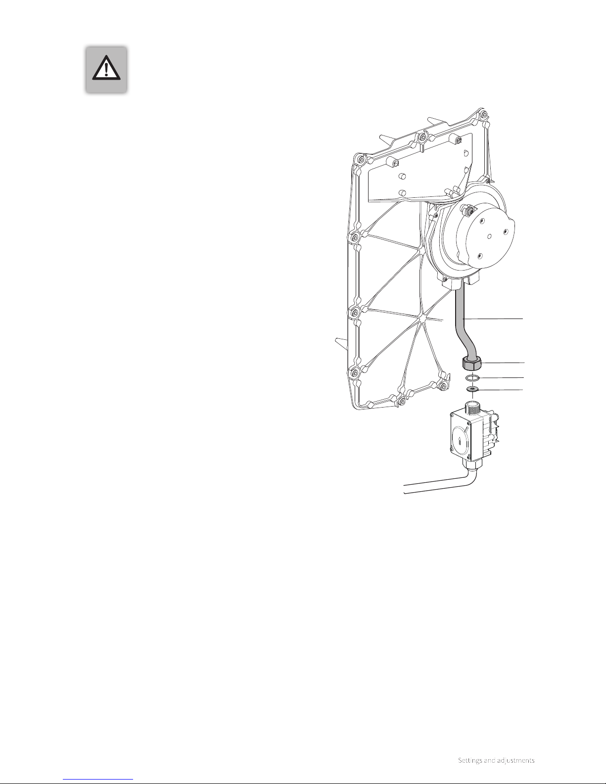
55
If the boiler is connected to another gas type than that for
which the boiler has been set by the manufacturer, the gas
restriction ring must be replaced. Conversion sets for other gas
types are available to order.
Conversion of the restriction ring
► Switch o the boiler and remove the plug from the wall
outlet.
► Close the gas valve.
► Remove the front panel of the boiler.
► Disconnect the connection above the gas valve and turn the
gas mixing pipe to the back.
► Replace the O-ring and the gas restriction ring with the rings
from the conversion set.
► Reconstruct it in reverse order.
► Open the gas valve.
► Check the gas connections before the gas valve for
tightness.
► Put the plug in the wall outlet and switch on the boiler.
► Check the gas connections aer the gas valve for tightness
(during operation).
► Now check the adjustment of the gas/air proportion (see
§8.10).
► Place a sticker indicating the newly set gas type over the
existing sticker near the gas valve.
► Stick the same sticker near the data plate.
► Assemble the front panel of the boiler.
8.8 Conversion to another gas type
Gas mixture pipe
Connection
O-ring
Gas restriction ring
CAREFUL
► Only qualified competent gas safe
registered engineers may work on the
boiler.
Page 56
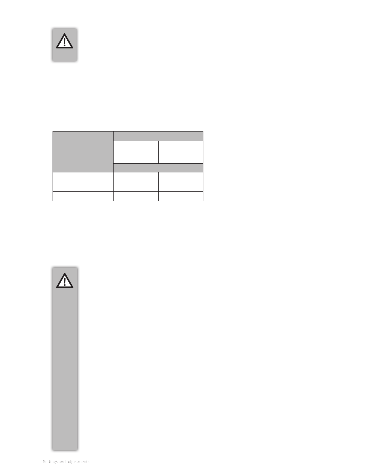
56
The gas/air control is set in the factory such that the
combustion is optimal for the gas type used. The gas type (natural gas
or LPG) for which the boiler is adjusted is indicated on the data plate
under the boiler. The boiler may not be implemented if the gas used
deviates form that which is indicated on the data plate. The boiler may
optionally be converted to another gas type using a conversion set.
For the correct gas restriction ring, see the table below.
Table 1: Gas restriction rings
Boiler type
Xtreme
Insert
number
Gas category
Natural gas
G20
20 mbar
LPG
G31
30 & 50 mbar
Gas restriction ring number
24 528 392 315
30 500 450 370
36 500 450 370
By default, the boiler is set to natural gas G20.
A proper operation of the gas air control can be established
by measuring the flue gases directly above the boiler using an
analyser probe of a flue gas analyser. The measurement takes
place at high and minimum output (for this, see §8.10.1 and
§8.10.2). Any deviation can be corrected solely at minimum
output by setting the gas valve anew (see §8.10.3).
IMPORTANT
► Inspection of the gas/air control must be
done with opened casing.
► The measurement must be performed
based on O2; in other words, the flue
gas analyser must have an O2 sensor.
Conversion of the measured O2
measurement value in the flue gas analyser
to a CO2 measurement value is allowed.
► The deviation of the flue gas analyser may
be a maximum of ± 0.3% (based on O2).
► A reliable check and adjustment is only
safeguarded if no extreme vacuum is
present in the flue connection opposite the
installation location. This also includes a
natural draught (wind), for example.
► A deviation at maximum output cannot
be corrected by adjusting the gas valve. In
that case, the boiler must be meticulously
inspected for gas density and correctness
of components used (especially the gas
restriction ring and the fan including
venturi).
► When replacing components and/or
converting to another gas type, the
operation of the gas air control must
always be inspected.
8.9 Gas/air control
IMPORTANT
► Work on gas supply pipe components
as well as the adjustment of the gas
air control must be performed by an
authorised installer.
Page 57
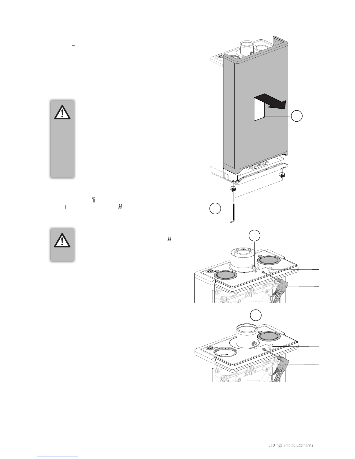
57
A. Switch o the boiler.
A line
– will appear on the right display and the central heating
pressure will be visible on the le display.
B. Remove the front panel of the boiler by unscrewing the 2
attachment screws (1) and then removing the panel forward (2).
C. Remove the cap of the flue gas measurement point (3) on the
flue adapter above the boiler.
D. Place the analyser probe of the flue gas analyser in the flue gas
measurement point.
IMPORTANT
► Make sure that the flue gas analyser is
calibrated. The start-up procedure of
the flue gas analyser must be completed
before the analyser probe is placed in the
flue gas measurement point.
► The analyser probe must completely seal
o the flue gas measurement point to
provide a reliable measurement.
► The end of the analyser probe must be
located entirely in the flue gases (middle
of the flue gas pipe).
IMPORTANT
► Make sure that the capital letter H
appears on the right display. This
provides assurance that the boiler is
operating as maximum load.
E. Switch on the boiler.
F. Switch on the boiler to maximum output. To do this, hold the
Service button and at the same time tap the Plus button
2x until the capital letter H appears on the right display.
G. Wait until the readout of the flue gas analyser is stable (at
least 3 minutes).
H. Note the measured O
2
(H) or CO2(H) value.
O2(H) ... = measured maximum output O2 value
CO2(H) ... = measured maximum output CO2 value
I. Check according to Table 2a or Table 2b whether the
measured maximum output O2(H) or CO2(H) value is
between the indicated upper and lower limits.
8.10 Inspection of gas air control
8.10.1 Measuring flue gas at maximum output
1
2
Cap
Flue gas
analyser
Flue gas
analyser
Cap
3
3
Page 58
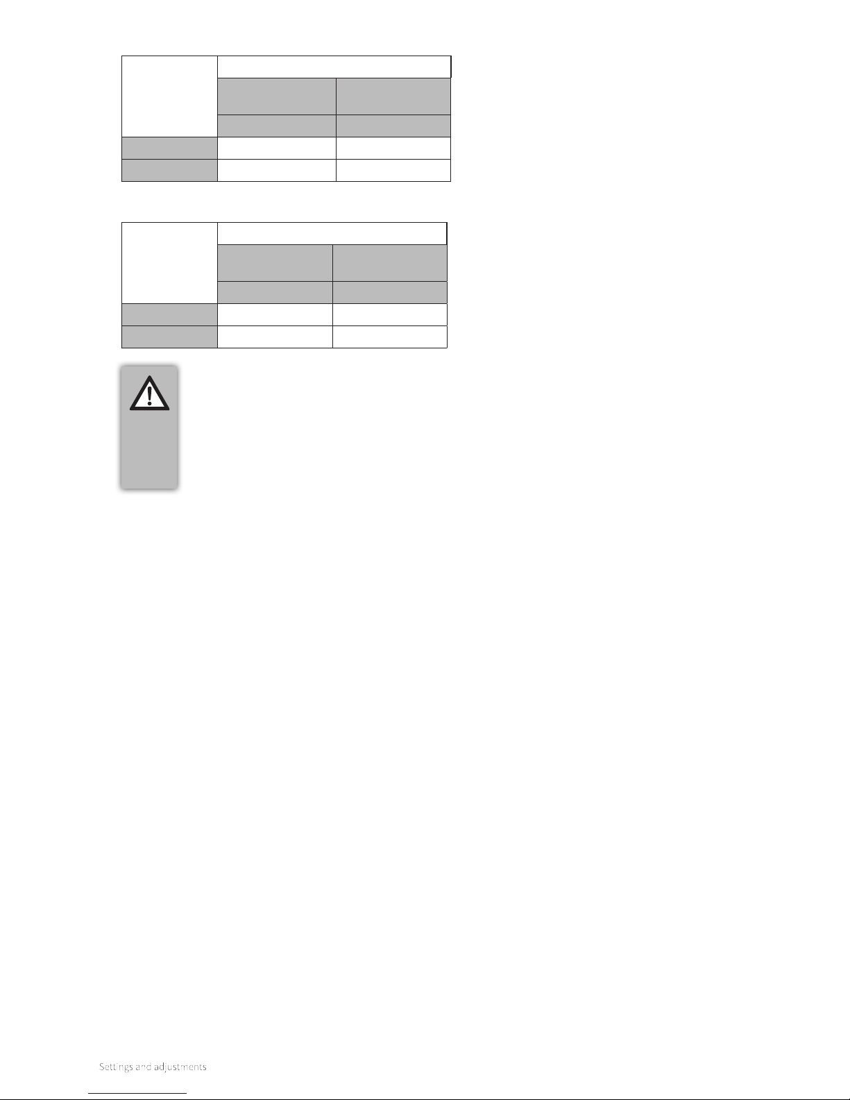
58
IMPORTANT
► A deviation at maximum output cannot
be corrected by adjusting the gas
valve. In that case, the boiler must be
meticulously inspected for gas density
and correctness of components used
(especially the gas restriction ring and
the fan including venturi).
Value limits
Gas category
Natural gas
G20
LPG
G31
O
2
[%] O2 [%]
Upper limit 5.60 6.05
Lower limit 3.85 4.50
Table 2a: Allowed O
2
(H) limits at maximum output (open casing)
Value limits
Gas category
Natural gas
G20
LPG
G31
CO
2
[%] CO2 [%]
Upper limit 9.6 10.8
Lower limit 8.6 9.8
Table 2b: Allowed CO
2
(H) limits at maximum output (open casing)
J. Then perform the measurement at minimum output (see
§8.10.2).
Page 59
59
Before measuring the flue gases at minimum output, the
measurement at maximum output must be completed.
The measured O2(H) or CO2(H) value at maximum output is
important for determining the correct value for the check at
minimum output. See §8.10.1 for measuring at maximum
output.
A. Switch on the boiler at minimum output. To do this, tap
simultaneously the Service button and the Minus button
until the capital letter L appears on the right display.
B. Wait until the readout of the flue gas analyser is stable (at
least 3 minutes).
C. Note the measured O
2
(L) or CO2(L) value.
O2(L) ... = measured minimum output O2 value
CO2(L) ... = measured minimum output CO2 value
D. Check according to Table 3a or Table 3b whether the
measured minimum output O2(L) or CO2(L) value is between
the indicated upper and lower limits.
► The O
2
lower limit is the O2(H) value that
was noted during the maximum output
measurement. The CO2 upper limit is the
CO2(H) value that was noted during the
maximum output measurement. (See
§8.10.1, Step H)
Table 3a: Allowed CO2(L) limits at minimum output (open
casing)
Table 3b: Allowed CO
2
(L) limits at minimum output (open
casing)
Value limits
Gas category
Natural gas
G20
LPG
G31
O
2
[%] O2 [%]
Upper limit 6.00 6.65
Lower limit O
2
(H) O2(H) + 0.5
Value limits
Gas category
Natural gas
G20
LPG
G31
CO
2
[%] CO2 [%]
Upper limit CO
2
(H) CO2(H) - 0.3
Lower limit 8.4 9.4
8.10.2 Measuring flue gas at minimum output
Page 60

60
Example (Natural gas G20)
► During maximum output a O2(H) value
of 4.0 % has been measured. In that case
the O2(L) value at minimum output must
be in-between 4 % (= value O2(H) and
6.05% as stated in the table. When during
minimum output a value out of this range
is measured the gas-air ratio must be
adjusted.
IMPORTANT
► The gas air control is correctly set if the
measured value at minimum output falls
within the indicated upper and lower
limits. Adjustment of the gas air control
is not necessary in this case. The setting
at minimum output must be adjusted
using the method described in §8.10.3
if the measured value lies outside the
indicated limits.
E. If the minimum output measurement falls outside the limits
given in Table 3a or 3b, continue at §8.10.3 to set up the
gas valve anew. If the setting is correct, continue to Step F.
F. Mount the front panel and fasten the 2 screws by hand.
Check the CO value at minimum output. The maximum
allowed CO measurement value is 160ppm.
G. Switch on the boiler to maximum output. To do this, hold
the Service button and at the same time tap the Plus
button 2x until the capital letter H appears on the right
display. Check the CO value at maximum output. The
maximum allowed CO measurement value is 160ppm.
H. Switch o the boiler.
I. Remove the analyser probe of the flue gas analyser from the
flue gas measurement point and carefully replace the cap
on the adapter above the boiler.
J. Switch on the boiler again.
K. Check the gas density of the flue gas measurement point.
Page 61
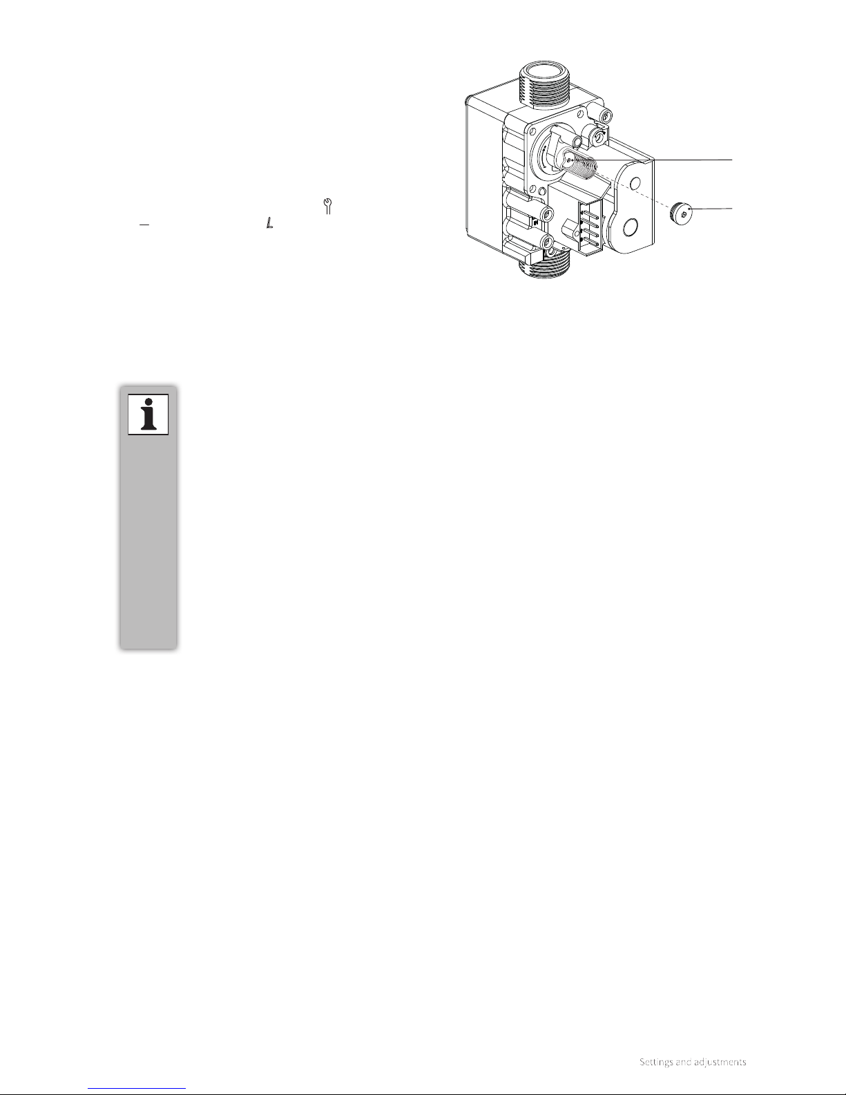
61
Before the min. output correction is performed, the maximum
output and minimum output measurements must be
completed. The measured O2(H) or CO2(H) value at maximum
output is important for determining the correct value for the
setting at minimum output (see §8.10.1 and §8.10.2).
A. Remove the cover screw of the gas valve so that the
adjustment screw is accessible.
B. Switch on the boiler at minimum output. To do this, tap
simultaneously the Service button and the Minus button
until the capital letter L appears on the right display.
C. Wait until the readout of the flue gas analyser is stable (at
least 3 minutes).
D. Measure the O2(L) or CO2(L) value.
E. Using the adjustment screw B, set the correct O2(L) or CO2(L)
value. For the correct O2(L) setting value, see Tables 4a, 4b
or 4c. For the correct CO2(L) setting value, see Tables 5a, 5b
or 5c.
F. Reattach the cover screw of the gas valve so that the
adjustment screw is sealed.
► Select the correct table depending on the
applicable gas category:
4a and 5a: natural gas (G20)
4b and 5b: LPG 3P (G31)
► The maximum output measurement
value is decisive for a correct
adjustment. This measurement value
was noted during the maximum output
measurement O2(H) or CO2(H) (see
§8.10.1, Step H).
► Turning the adjustment screw to the
right reduces O2 (and increases CO2);
turning to the le increases O2 (and
decreases CO2).
► Twist the adjustment screw with small
steps and wait aer each twist until the
measurement is stable.
8.10.3 Minimum output correction
Adjustment screw
Cover screw
Page 62
62
Table 4b: Determination of O2(L) setting value for
LPG (open casing)
LPG G31 (30 & 50 mbar)
Measured value at
maximum output
(see §8.10.1, Step H)
Setting value minimum
output
(= 0.5 x O
2
(H) + 0.5)
O
2
(H) [%] CO2(L) [%]
6.05 6.55 ± 0.2
5.70 6.20 ± 0.2
5.40 5.90 ± 0.2
5.10 5.60 ± 0.2
4.80 5.30 ± 0.2
4.50 5.00 ± 0.2
Table 5a: Determination of CO2(L) setting value for
natural gas 2EK (open casing)
Table 5b: Determination of CO
2
(L) setting value for
LPG (open casing)
G. Repeat the measurements at maximum output and
minimum output noted in §8.10.1 and §8.10.2 (start with
Step F in §8.10.1) to ensure the correct operation of the
boiler.
LPG G31 (30 & 50 mbar)
Measured value at
maximum output
(see §8.10.1, Step H)
Setting value minimum
output
(= CO
2
(H) - 0.3)
CO
2
(H) [%] CO2(L) [%]
10.8 10.5 ± 0.1
10.6 10.3 ± 0.1
10.4 10.1 ± 0.1
10.2 9.9 ± 0.1
10.0 9.7 ± 0.1
9.8 9.5 ± 0.1
Example (when using natural gas G20)
► During maximum output, an O2(H) value of
4.10% is measured. In that case, the minimum
output O2 setting value is 5.05 ± 0.2%.
Table 4a: Determination of O2(L) setting value
natural gas (open casing)
Natural gas G20 (20 mbar)
Measured value at
maximum output
(see §8.10.1, Step H)
Setting value minimum
output
(= 0.5 x O
2
(H) + 3.05)
O
2
(H) [%] CO2(L) [%]
5.60 5.80 ± 0.2
5.30 5.65 ± 0.2
5.00 5.50 ± 0.2
4.70 5.35 ± 0.2
4.40 5.20 ± 0.2
4.10 5.05 ± 0.2
3.85 4.90 ± 0.2
Natural gas G20 (20 mbar)
Measured value at
maximum output
(see §8.10.1, Step H)
Setting value minimum
output
(= 0.5 x CO
2
(H) + 4.1)
CO
2
(H) [%] CO2(L) [%]
9.6 9.0 ± 0.1
9.4 8.9 ± 0.1
9.2 8.8 ± 0.1
9.0 8.7 ± 0.1
8.8 8.6 ± 0.1
8.6 8.5 ± 0.1
Page 63
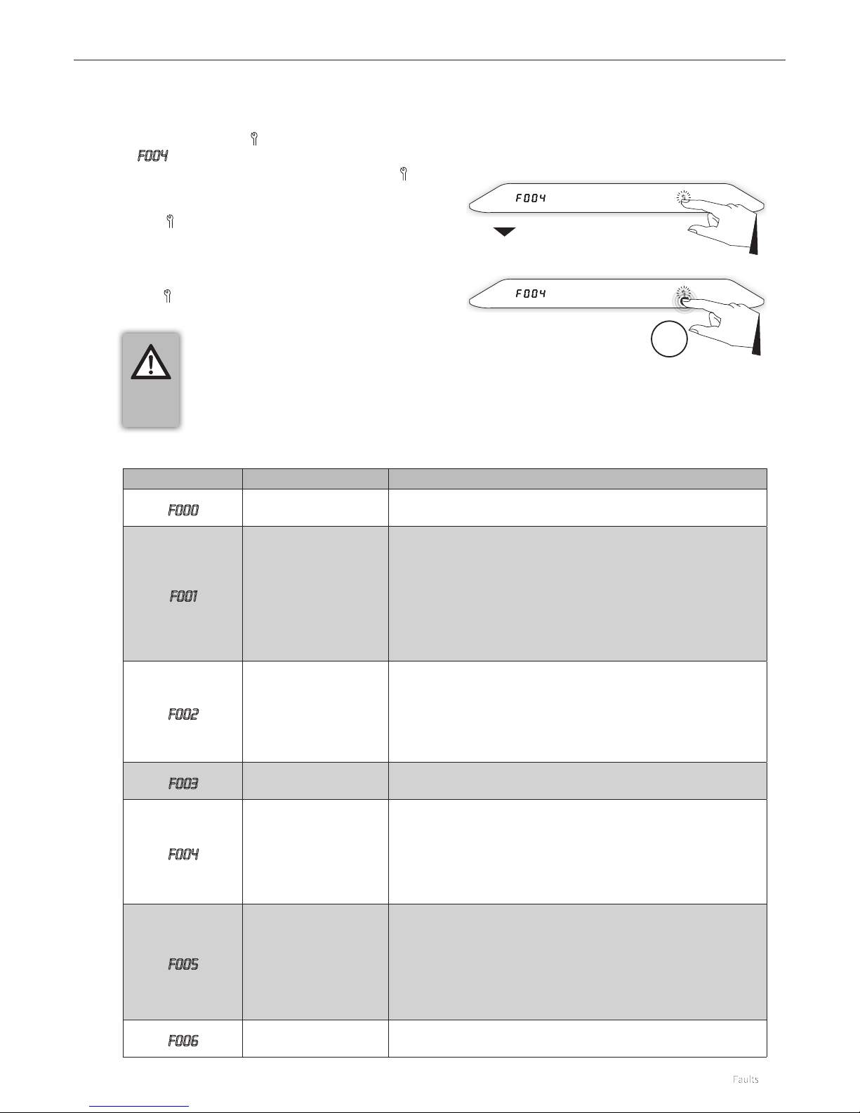
63
Fault code Description Possible cause / solution
F000
Sensor S0 is defective. ► Replace heat exchanger sensor S0.
F001
Temperature is too high
during central heating
demand.
► Air in system. Bleed the central heating system.
► Pump does not run. Replace the pump.
► Check wiring of central heating flow sensor S1 for breakage/
shutdown.
► Check whether central heating flow sensor S1 is installed
correctly.
► Check for the correct operation of central heating flow sensor S1.
► Replace central heating flow sensor S1.
F002
Temperature too high
during DHW demand.
► Check wiring of domestic hot water sensor S3 for breakage/
shutdown.
► Check whether domestic hot water sensor S3 is installed
correctly.
► Check for the correct operation of domestic hot water sensor S3.
► Replace domestic hot water sensor S3.
F003
Flue gas temperature is
too high.
► Check heat exchanger for contamination.
F004
No flame during start-up.
► Gas valve is closed.
► Gas inlet pressure lower than 20mbar or sometimes disappears.
► Condensation drain is blocked.
► Check ignition unit.
► Gas valve or ignition unit is not receiving electricity.
► Poor internal grounding.
F005
Flame disappears during
operation.
► Condensation drain is blocked.
► Gas inlet pressure lower than 20mbar or sometimes disappears.
► Check ignition unit.
► Check adjustment of gas valve.
► Check air supply duct and flue for possible recirculation or
blockage of flue gases.
► Poor internal grounding.
F006
Flame simulation.
► Replace gas valve.
► Replace burner controller.
9 FAULTS
The following fault codes can be distinguished:
9.1 Fault codes
IMPORTANT
► Using the fault code, check the table
below for the nature of the fault and try
to address the cause of the fault as much
as possible before resetting the boiler.
Requesting fault code
Resetting the boiler
If the burner controller detects a fault, this is shown by a
flashing service symbol
on the display. A fault code, such
as F004, is shown on the le display for 30 seconds. Then the
le display will be extinguished. The service symbol remains
flashing.
The fault code can be requested by tapping the flashing service
symbol .
Requesting fault code
The boiler can be reset by touching the flashing Service
button and holding it for 2 seconds. The boiler will then be
restarted.
Reset
2sec
Page 64
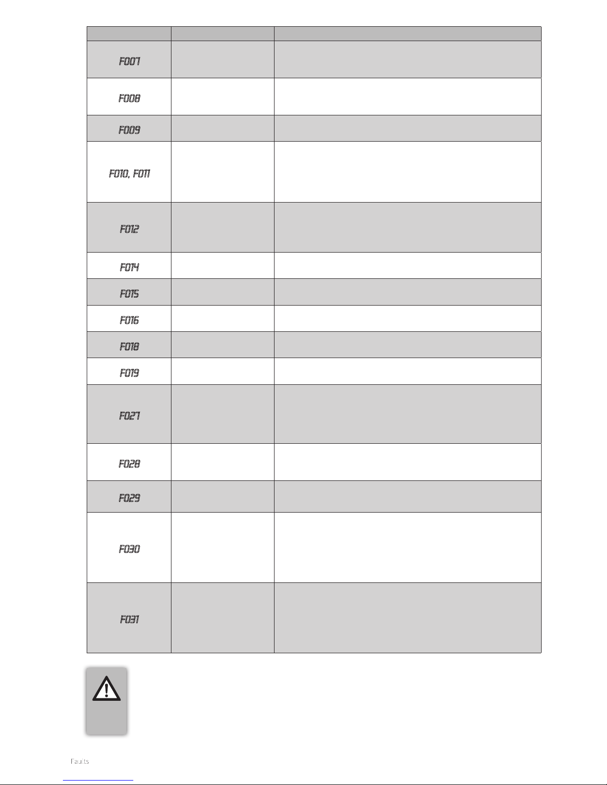
64
IMPORTANT
► Replace defective components
exclusively with original Intergas
components.
► Not or incorrectly installing the sensors
can lead to serious damage.
Fault code Description Possible cause / solution
F007
No or insuicient
ionisation flow.
► Check ionisation/ignition pin.
► Check wiring of ionisation/ignition pin for breakage/shutdown.
► Replace ionisation/ignition pin.
F008
Incorrect fan speed
► Check fan cable.
► Check and/or replace fan.
► Replace burner controller.
F009
Internal fault in burner
controller.
► Replace burner controller.
F010, F011
Sensor fault S0.
► Check the wiring of heat exchanger sensor S0 for breakage/
shutdown.
► Check whether heat exchanger sensor S0 is connected correctly.
► Check for the correct operation of heat exchanger sensor S0.
► Replace heat exchanger sensor S0.
F012
Sensor fault S5.
► Check the wiring of flue gas sensor S5 for breakage/shutdown.
► Check whether flue gas sensor S5 is connected correctly.
► Check for the correct operation of flue gas sensor S5.
► Replace flue gas sensor S5.
f014
Mounting fault sensor S0
► Heat exchanger sensor S0 is not mounted correctly. Mount the
sensor correctly.
f015
Mounting fault sensor S1
► Central heating flow sensor is not mounted correctly. Mount the
sensor correctly.
f016
Mounting fault S3
► Domestic hot water sensor S3 is not mounted correctly. Mount
the sensor correctly.
F018
Flue and/or air supply
duct is blocked.
► Check the flue and the air supply duct.
► Clean the flue and/or the air supply duct.
F019
BMM fault.
► Check BMM wiring for breakage/shutdown.
► Replace BMM.
F027
Short circuit of outdoor
sensor S6.
► Check the wiring of the outdoor sensor for breakage/shutdown.
► Replace the outdoor sensor.
► BRINK WTW connection piece is connected. Burner controller is
unsuitable for this application. Replace burner controller with the
correct version.
f028
Reset error.
► Check the reset button for unintentional operation (e.g. cleaning
of control panel).
► Replace burner controller.
f029
Gas valve fault.
► Check the gas valve for leakage.
► Replace the burner controller.
F030
Sensor fault S3.
► Check wiring of domestic hot water sensor S3 for breakage/
shutdown.
► Check whether domestic hot water sensor S3 is connected
correctly.
► Check for the correct operation of domestic hot water sensor S3.
► Replace domestic hot water sensor S3.
F031
Sensor fault S1.
► Check wiring of central heating flow sensor for breakage/
shutdown.
► Check whether central heating flow sensor S1 is connected
correctly.
► Check for the correct operation of central heating flow sensor S1.
► Replace central heating flow sensor S1.
Page 65

65
9.2 Other faults
9.2.1 No heat (central heating)
Possible causes Analysis Solution
The power LED is not shown. Yes
↓ No
Check the power supply.
Check the fuse; see Electrical schematic §11.1 .
The right display shows a line (
–).
The boiler is o.
Yes
↓ No
Switch on the boiler by touching just above the power LED and
holding this for 2 seconds
Room thermostat / weatherdependent control is not connected
or is defective.
Yes
↓ No
Check the wiring.
Check OpenTherm, On/O connection of the boiler, or the
connection between the central heating boiler and the
OpenTherm room thermostat. Replace the thermostat.
Replace the weather-dependent control.
No electricity (24V). Yes Replace defective automatic. Check the wiring according to the
schematic.
Check Connector X13.
9.2.2 Central heating does not reach the correct temperature
Possible causes Analysis Solution
Water pressure in the system is too
low.
Yes
↓ No
Top o the system; see §7.2.1.
Room thermostat is not in order.
Yes
↓ No
Check the setting and adjust it if necessary.
Temperature is set too low. Yes
↓ No
Increase the central heating temperature; see central heating
demand. If an outdoor sensor is present:
Check the outdoor sensor for short circuiting: cancel this.
No flow in the system. Yes
↓ No
Check the T (±20°C) between central heating supply and
return. Ensure a correct flow in the system.
The boiler capacity is not correctly
set.
Yes
↓ No
Adjust the boiler capacity. See §8.3 and §8.6.
No heat transfer due to
contamination in the central heating
boiler/system.
Yes
↓ No
Flush the central heating boiler/system from the central heating
side.
Flue and/or air supply duct is blocked. Yes Check and (if necessary) clean the flue and the air supply duct.
9.2.3 Central heating system remains too warm
Possible causes Analysis Solution
Room thermostat / weatherdependent control is defective or has
a short circuit.
Yes
↓ No
Check the wiring.
Check OpenTherm, On/O connection of the boiler, or the
connection between the central heating boiler and the RF
room thermostat. Replace the thermostat.
Replace the weather-dependent control.
There is thermo-siphon in the central
heating circuit.
Yes
Place a check valve (in the case of thermo-siphon) or a two-way
valve (if there is a second pump in the central heating circuit).
Page 66
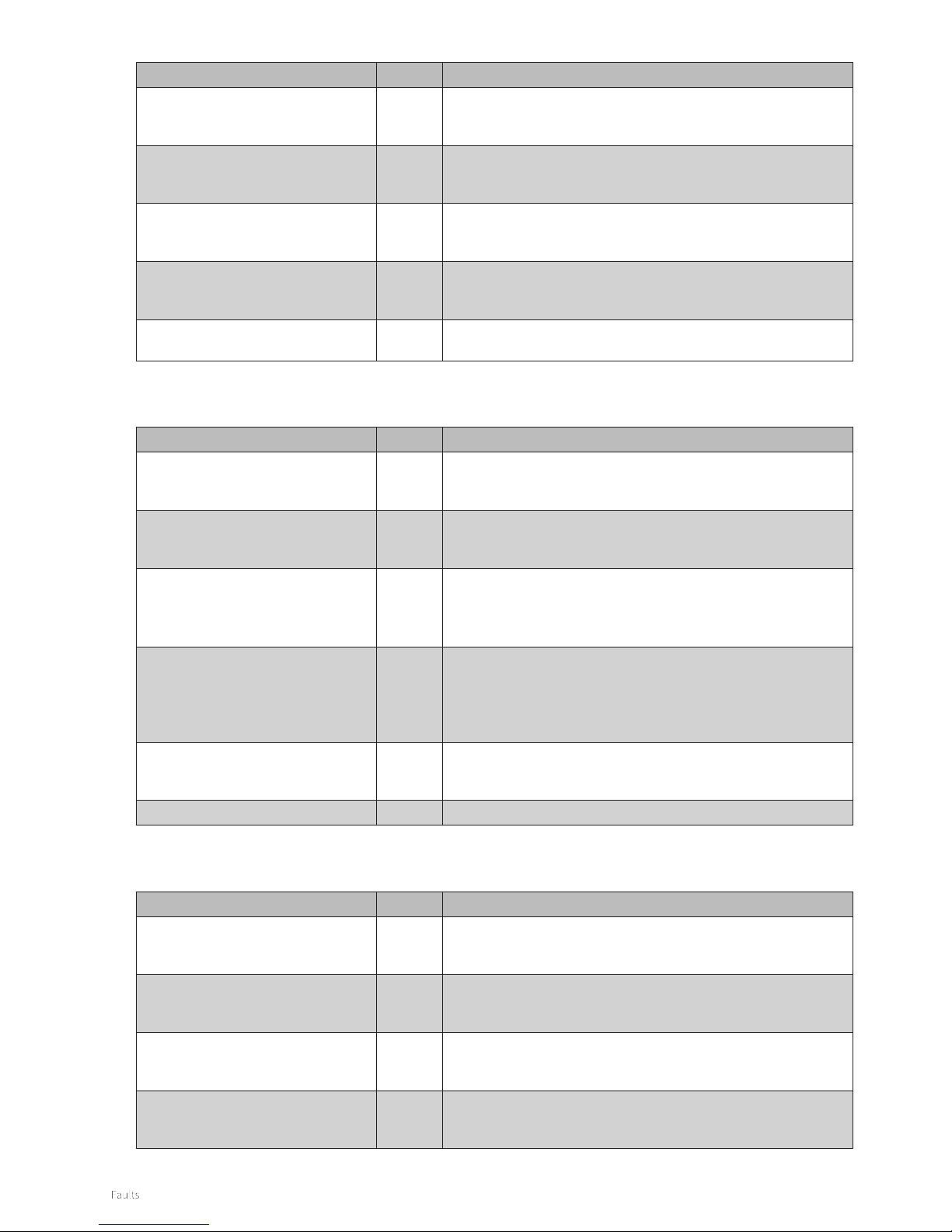
66
9.2.4 No domestic hot water (DHW)
9.2.5 Domestic hot tap water does not reach the correct temperature
Possible causes Analysis Solution
The power LED is not shown. Yes
↓ No
Check the power supply.
Check the fuse; see Electrical schematic § 11.1.
Flow sensor does not work.
Yes
↓ No
Replace the flow sensor.
Domestic hot water flow < 2l/min. Yes
↓ No
Increase the domestic hot water flow.
Domestic hot water sensor S3 is
defective.
Yes
↓ No
Replace domestic hot water sensor S3.
No electricity on the flow sensor (5V
DC).
Yes Check the wiring according to the schematic.
Possible causes Analysis Solution
Domestic hot water flow is too high. Yes
↓ No
Reduce the domestic hot water flow.
Setting for domestic hot water
temperature is too low.
Yes
↓ No
Increase the domestic hot water temperature; see §8.1.2.
Insuicient heat transfer due to
calcium or contamination in the
domestic hot water-sided central
heating boiler.
Yes
↓ No
De-calcify or flush the domestic hot water-sided central heating
boiler.
The central heating system becomes
warm while tapping water.
Yes
↓ No
Undesirable circulation during domestic hot water demand in
the central heating circuit due to thermo-siphon of the second
pump in the central heating circuit. Place a check valve (in the
case of thermo-siphon) or a two-way valve (if there is a second
pump).
Central heating pressure is too low. Yes
↓ No
Top o the central heating system until the central heating
pressure is between 1 and 2bar.
The flue is blocked. Yes Check the flue.
Possible causes Analysis Solution
Inlet pressure is too high. Yes
↓ No
The home pressure regulator may be defective. In that case,
contact the energy company.
Ignition distance is incorrect.
Yes
↓ No
Replace the ignition pin including the ignition cable.
Gas-air control is not correctly
adjusted.
Yes
↓ No
Check the adjustment; see §8.9 and §8.10.
The spark is weak. Yes Check and/or replace the ignition cable.
Replace the ignition unit in the top cover.
Replace the ignition pin.
9.2.6 Burner ignites loudly
Page 67
67
9.2.7 Burner resonates
Possible causes Analysis Solution
Gas inlet pressure lower than 20mbar
or sometimes disappears.
Yes
↓ No
The home pressure regulator may be defective. Contact the
energy company.
There is recirculation of flue gases.
Yes
↓ No
Check the flue and air supply duct.
Gas-air control is not correctly
adjusted.
Yes
↓ No
Check the adjustment; see §8.9 and §8.10.
Burner seal is defective. Yes
↓ No
Replace the burner seal.
Burner is defective. Yes
Replace the burner.
Page 68
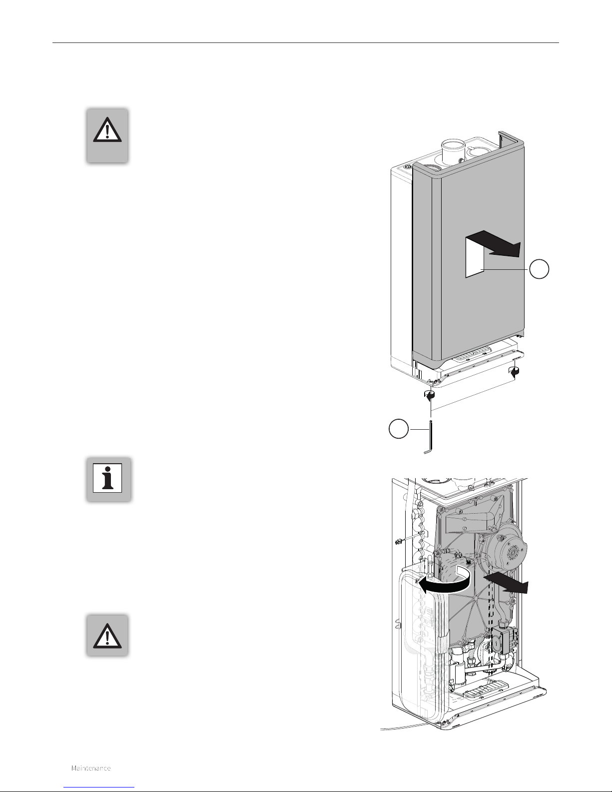
68
10 MAINTENANCE
► Clean the slats of the heat exchanger from top to bottom with a
brush or vacuum cleaner.
► Clean the underside of the heat exchanger.
► Clean the siphon with water.
► Only clean the underside of the front panel.
CAREFUL
► The integrated insulation panel and burner
seal contain ceramic fibres.
CAREFUL
► Aer work activities, check all flue supply
piping parts for tightness.
► Some components can be hot when the boiler
has just been in operation.
10.1 Disassembly
10.2 Cleaning
The boiler and the system must be inspected annually by an qualified competent gas safe registered engineer and
cleanded if necessary. The annual maintenance interval is based on an expected operation time of approx. 1,500 heating
hours/year (average domestic use), via Comfort Touch dashboard and installerd app. If not monitored by Comfort Touch
then the boiler must be serviced annually.
1
2
► Switch o the appliance and isolate the power supply at the fuse
spur, make safe the appliance before continuing (Ref TB118).
► Close the gas valve.
► Remove the front panel of the boiler by unscrewing the two
screws (1) and then removing the panel up and forward (2).
► Wait until the boiler has cooled down. This can be done by
opening a domestic hot water tap.
► Turn the expansion vessel aside.
► Disconnect the connector of the fan.
► Disconnect the connection under the gas valve.
► Unscrew the shoulder bolts (socket) of the front cover and
remove the cover forward with the gas valve and fan (pay
attention that the burner, insulation panel, gas valve, gas piping
and the fan do not become damaged). Lay the removed front
cover with the foot supports horizontal on a smooth surface.
► The burner and the integrated insulation panel do not require
maintenance (do not need to be cleaned). Therefore, never use a
brush or compressed air to clean these components so that the
development of dust is avoided.
► Remove the siphon cup by turning it counter-clockwise and then
removing it downwards.
COMMENT
► The expansion vessel must be inspected and
tested at each annual service and if required
re-pressure to 0.75 bar.
Page 69
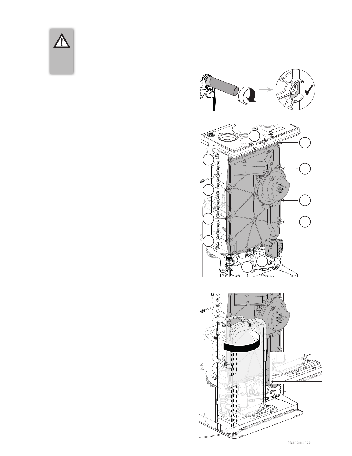
69
► Check whether there is a thin layer of ceramic grease
between the flange of the shoulder bolt and the front panel.
If there is insuicient grease present, extra must be applied:
► Check whether the gasket around the front panel is
correctly placed. Place the front panel on the heat
exchanger and attach it with the special shoulder bolts
(socket). Tighten the shoulder bolts (1 to 11) by hand,
working diagonally. For the order of tightening, see the
picture.
► Verify the shoulder bolts according to the same order with a
torque spanner at 10-12Nm.
► Tighten the burner bolts diagonally by hand.
► Check the gasket and fit the gas connection under the gas
valve.
► Install the connector on the fan.
► Open the gas valve and check the gas connections under
the gas valve for leakage.
► Check the water supply piping for leakage.
► Fill the siphon cup to just over half full.
► Replace the siphon cup by sliding it over the siphon spout
and then turning it clockwise until it is secure. Check
whether the siphon spout is sticking into the water and
check whether the siphon cup is firmly in place.
► Turn the expansion vessel back to its original position. Make
sure the vessel is secured by the lip on the cable cover.
► Turn the power supply on at the fuse spur.
► Switch on the boiler.
► Check the front cover, the connection of the fan on the front
cover, and the flue components for leakage.
► Check the gas/air control (see §8.9 and §8.10) and check
the gas connection on the gas valve for tightness.
► Install the casing and tighten the two screws at the le and
right under the boiler.
► Check the domestic hot water facility for correct operation.
10.3 Installation
1
2
3
4
5
6
7
8
9
10
11
IMPORTANT
► Replace the front plate O-ring every 3
years.
Art.no: 877927 — Xtreme 24/30
620274 — Xtreme 36
► Check and replace any other gaskets.
Also check the correct positioning.
Page 70
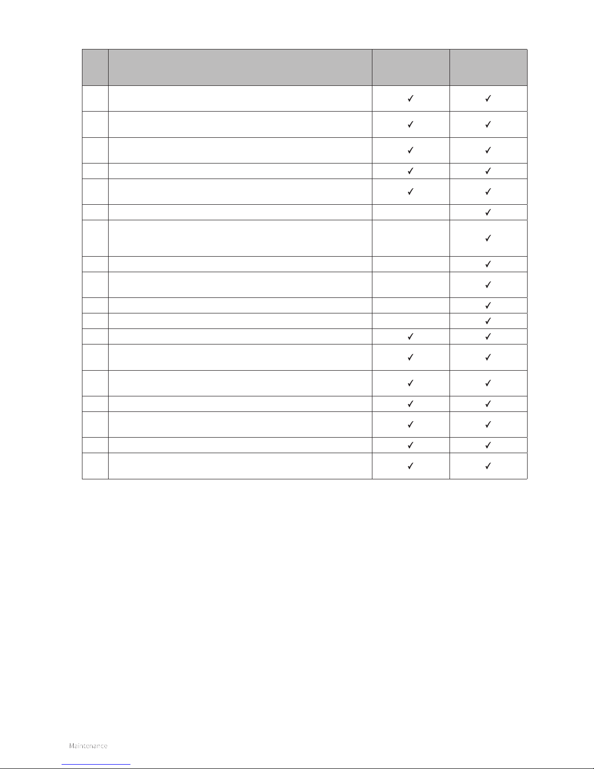
70
No. Activity Inspection at
every annual
service
Maintenance
must be carried
out at regularly
1 Isolate the boiler from the fuse spur and make safe (ref TB118) check
the correct 3amp fuse fitted.
2 Carry out inspection of boiler for dust and dirt and clean where
necessary.
3 Visually inspect the front plate and heat exchange for signs of
damage. If damage is evident proceed to column 2.
4 Check the gas inlet pressure on HIGH rate (DHW mode).
5 Check combustion by measuring CO, CO2. If the values are outside the
tolerances then proceed to a full service in column 2.
6 Close the gas isolation valve.
7 Isolate flow and return valves and drain boiler via the drain o on
the return. Check the charge in the expansion vessel. Recharge if
necessary.
8 Remove the front plate and clean the inside of the heat exchanger.
9 Check the front plate seal and replace the seal if damaged or the seal
is 3 years old..
10 Check the burner and burner seal.
11 Check the ignition pin.
12 Check the condensate trap, clean and fill.
13 Open the isolation valves on flow and return and refill the water in the
boiler to 1.2 bar via the filling loop.
14 Open the gas isolation valve, reconnect the power to the boiler via
fuse spur.
15 Check visually the ignition and burner performance.
16 Check the boiler for leaks of any kind (gas, flue gas, water,
condensate) rectify if necessary.
17 Recheck the CO,CO2 and adjust if necessary, adjust CO2 only LOW fire.
18 Complete the Benchmark Service Record on the back pages of the
Installation manual.
10.4 Checklist
Page 71
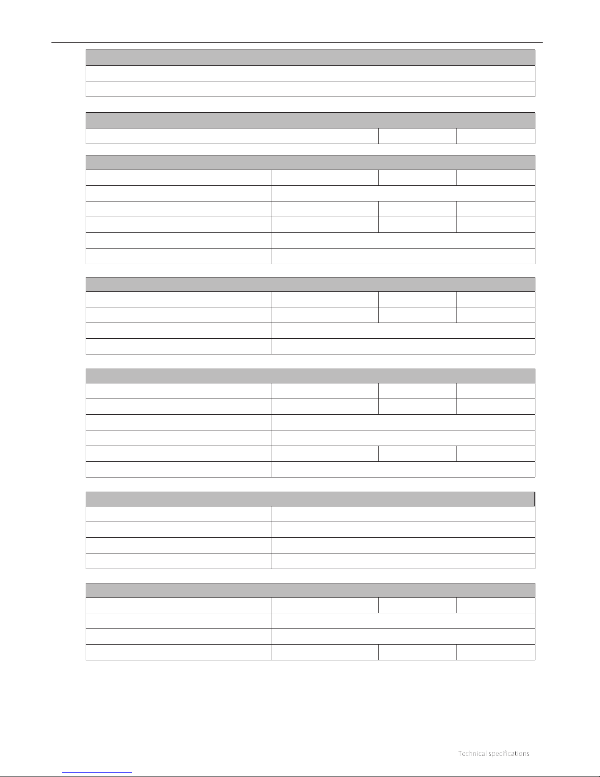
71
11 TECHNICAL SPECIFICATIONS
Boiler category C13; C33; C53
Gas inlet pressure G20: 20 mbar, G31: 37 mbar
Suitable for gas II
2H3P
Technical data
Xtreme
24 30 36
Electric data
Mains voltage V
230
Safety class IP
IPX4D
Recorded output: full load W
115
Recorded output: standby W
2
Other data
Gas consumption (G20) m3/h
0.38 – 2.66 0.38 – 3.23 0.38 - 3.46
Gas consumption (G31) m
3
/h
0.15 – 1.03 0.15 – 1.25 0.15 – 1.34
Appliance pressure loss (CH) mWk
See §8.6
Average flue temperature DHW °C
35
Flue massflow (minimum-maximum) kg/h
5.9 – 41.6 5.9 – 50.5 5.9 – 54.1
Maximum counterpressure Pa
250
Overall dimensions and weight
Height mm
766 766 826
Width mm
450
Depth mm
277
Weight kg
33 33 36
Domestic hot water
Nom. input rating (lower value) kW
3.6 – 25.1 3.6 – 30.5 3.6 – 32.7
Tap threshold l/min
2
T 25°C l/min
15.3 18.7 20.3
T 35°C l/min
11 13.3 14.5
Domestic hot water temperature (default) °C
55
Domestic hot water-sided pressure dierence bar
see §6.2.1
Central heating
Nom. input rating (lower value) kW 3.6 – 18.7 3.6 – 23.7 3.6 – 27.0
Nom. output kW 4.0 – 18.2 4.0 – 23.1 4.0 – 26.6
Max. Central heating water pressure bar
3
Max. Central heating water temperature °C
90
Page 72
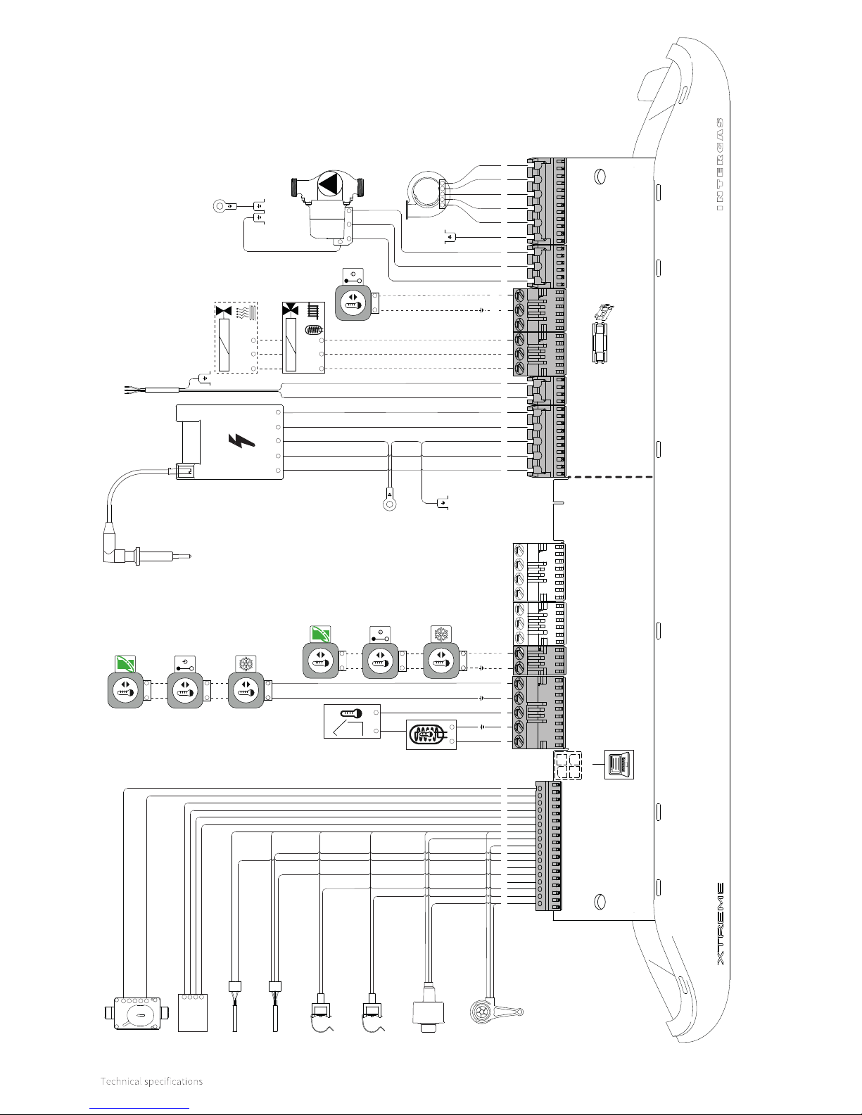
72
11.1 Electrical schematic
17
16
1415
13
12 11 10 9 8 7
6
5 4 3 2
1
Flow ssensor
Central heating flow sensor S1
Domestic hot water sensor S3
Heat exchanger sensor S0
Flue sensor S5
BMM
4
321
5
4
3
2
1
Gasvalve
X15
(24V=)
X14
PC
12345
12 12345 123
X13
(24V =)
X12
(24V =)
X11
(24V =)
N/A
X10
(24V =)
N/A
X8
(230V ~)
X5
(230V ~)
Ignition unit
Burner controller
123 123456
Earth connections
heat exchanger
Power cord
Earth connections
burner controller
Fan
Central heating pump
230V~ / 50Hz
Ignition pin
230V ~
24V =
4
5
3
4
Central heating pressure sensor
2
1
3
2
1
3
OpenTherm thermostat
OpenTherm thermostat
Outdoor sensor S6
Boiler sensor S7
3
2
1
4
3
5
http://www.intergasverwarming.nl
X4
(230V ~)
X3
(230V ~)
X2
(230V ~)
3
2
1
1
2
3
4
5
X1
(230V ~)
12
12
12
On
O
On/o thermostat
Frost thermostat
12
12
12
On
O
On/o thermostat
Frost thermostat
12
4
On
O
On/o
thermostat
12
12
LS
F1 (3,15 AT)
FUSE
Page 73
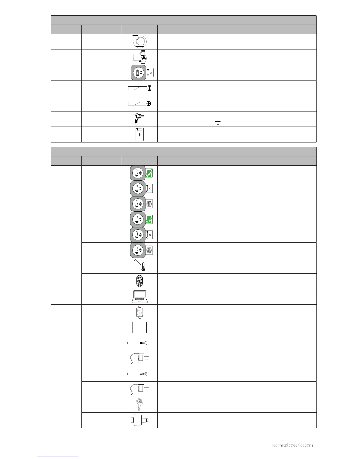
73
230V~ component
Connector Connections Designation Description
X1
1 – 2 – 3 – 4 –
5 – 6
Fan
X2 1 – 2 – 3
Central heating pump
X3 1 – 2
On
O
On/o room thermostat 230V
X4
1 – 2 – 3
Shut-o valve underfloor heating or groups adjustment
(1=N (blue), 2=L (brown), 3=T (black))
1 – 2 – 3
Three-way valve
(1=N (blue), 2=L (brown), 3=T (black))
X5 1 – 2
Power mains cord 230V~ 50Hz
(1=L (brown), 2=N (blue), = ground (green/yellow))
X8 1 – 2 – 3 – 4 – 5
3
Ignition unit
24V = component
Connector Connections Designation Description
X12 1 – 2
OpenTherm thermostat
X12 1 – 2
Aan
Uit
On/o room thermostat
X12 1 – 2
Frost thermostat if OT thermostat on X13
X13
1 – 2
OpenTherm thermostat (primary connection)
1 – 2
Aan
Uit
On/o room thermostat
1 – 2
Frost thermostat
3 – 4
Outdoor sensor S6 (12k / 25°C)
4 – 5
Boiler sensor S7
X14
PC Interface
X15
1 – 2
Gas valve
3 – 4 – 5 – 6
BMM
BMM (Boiler Memory Module)
7 – 11
Flue gas sensor S5
7 – 16
Domestic hot water sensor S3
7 – 10 – 13
Heat exchanger sensor S0
7 – 15
Central heating flow sensor S1
7 – 9– 17
Flow sensor
7 – 8– 17
Central heating pressure sensor
Page 74
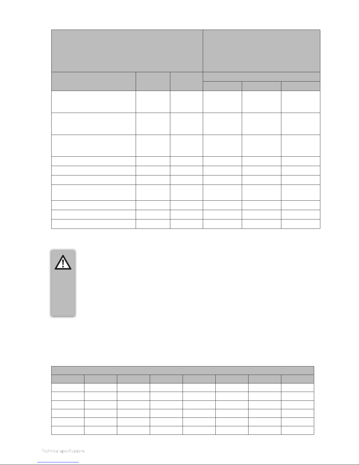
74
11.3 NTC resistances
NTC 12 kOhm
T [°C] R [Ω] T [°C] R [Ω] T [°C] R [Ω] T [°C] R [Ω]
-15 76020 15 18300 45 5522 75 1994
-10 58880 20 14770 50 4609 80 1717
-5 45950 25 12000 55 3863 85 1467
0 36130 30 9805 60 3253 90 1266
5 28600 35 8055 65 2752 95 1096
10 22800 40 6653 70 2337 100 952
11.2 Product card according to CELEX-32013R0811, Appendix IV
IMPORTANT
► Before installation, read the installation manual and the operation instructions.
► This appliance is not intended for use by individuals (including children) with reduced
physical, sensory or mental capacities, or lack of experience and knowledge, unless
supervision of or instruction about the use of the appliance is given by a person who is
responsible for their safety.
► The boiler and system must be inspected annually by an authorized installer and cleaned if
necessary. See §10 for the annual cleaning.
► The boiler can be cleaned with a damp cloth. Do not use aggressive or scrubbing cleaning
agents or solvents.
Supplier
Intergas Heating Ltd
Unit 2
Easter Park
Worcester Road
Kidderminster
DY11 7AR
Type designation Symbol Unit
Intergas Xtreme
24 30 36
Seasonal energy eiciency class for
room heating
- - A A A
Nominal heat output (capacity) P
rated
kW 18 23 27
Seasonal energy eiciency class for
room heating
ŋ
s
% 93 93 93
Annual energy use Q
HE
GJ 38 48 58
Noise level L
WA
dB 56 56 58
Domestic hot water capacity profile - - L XL XXL
Energy eiciency class for water
heating
- - A A A
Domestic hot water eiciency ŋ
WH
% 89 91 94
Annual electricity use AEC kWh 13 14 20
Annual fuel use AFC kWh 2834 4536 5796
Page 75
The product must be registered via the internet at
www.intergasheating.co.uk or on the Intergas MiREG
website www.myintergasregistration.co.uk or by returning
the warranty card.
3. The boiler must be serviced annually by a registered Gas Safe
Engineer in accordance with manufacturer’s instructions.
4. Service details must be recorded in the Benchmark Checklist
or provide proof of service which must be available for
inspection.
5. The cost of the annual service is not included in the warranty.
If the above conditions are not meet this warranty will be
limited to 12 months from the date of installation or date of
Manufacture, as recorded on the Benchmark commissioning
checklist.
1. The installer must be registered with Gas Safe, installer must
complete the Benchmark Commissioning Checklist in full at
the time the boiler is installed. The Benchmark must be made
available and can be found at the back of the installation
instructions. The Benchmark Commissioning Checklist must
be retained on site by the owner/occupier for inspection
during an engineers visit.
2. The boiler warranty must be registered with Intergas by either
the installer or you the householder, within 30 days of the
boiler being installed. For the new build properties, this must
be done within 30 days of the sale being completed. If these
conditions are not met, the warranty will not be valid.
Manufacturer Intergas Heating Limited
Address Unit 2
Easter Park
Worcester Road
Kidderminster
DY11 7AR
hereby declares that CH appliance:
INTERGAS, Type:
Meets the provisions of the following directives:
► Low Voltage Directive (2014/35/EC)
► Gas Appliance Regulation (2016/426/EC)
► Directive regarding eiciency requirements for new oil and gas-
burning central heating boilers (92/42/EC)
► EMC Directive (2014/30/EC)
► RED Directive (2014/53/EC)*
► Ecodesign (2009/125/EG)
► Energy labelling (2010/30/EU)
* The conformity declaration can be requested from Intergas.
S. Zouch, January 2019
CE DECLARATION
75
6. Only boiler component failures are covered by the warranty.
The warranty does not cover any connected system or
accessories such as time switches, thermostats, motorised
valves, external pumps and so on.
7. Any repair carried out under the terms of this warranty does
not extend the warranty beyond its original period.
8. If the boiler breaks down, Intergas may ask you* (Homeowner
or Installer) to pay a deposit before we visit to complete the
repair. We will return the deposit in full if we find a fault that
is covered by the warranty. We may keep the deposit if we
cannot access the property at the time we have arranged with
you to visit or we find other conditions of this warranty have
not been met.
9. The system must be flushed and cleansed in accordance with
BS7593.
10. If any failure is caused by contaminated water in the system
the engineer visit becomes chargeable.
11. All installation, non boiler or external system faults calls will be
charged to the home owner/occupier.
12. Roof space installation BS6798 2009 Require a permanently
fixed access ladder must service installations in los or attics.
Adequate lighting and permanently fixed flooring must also be
available.
13. Engineers will not carry out repairs if they think accessing the
boiler would be a risk to Health and Safety. A responsible adult
must be at the property to give our engineer access to the
boiler.
14. If your boiler is in a cupboard, there must be enough room
for the engineer to work (the minimum area as set out in the
installation instructions). We are not responsible for removing
cupboards, kitchen units, trims etc to gain access for repairs.
IMPORTANT
Warranty terms mentioned above are based
on domestic use only. Any non-domestic
applications will be covered by a 12 months
warranty. Service intervals may need to be
increased depending on commercial usage.
For additional information please contact
Intergas Heating Ltd.
15.
In hard water areas of 200ppm or above, appropriate
protection actions must be taken in accordance with BS 7593
in line with building regulations Part L1. (Above 200ppm we
recommend Combimate*, Adey Electroscale or Hydroflow
HS38 should be installed. 300ppm and above we recommend
a Combimate* or Water soener* should be installed.)
(*serviceable item)
16. The central heating system must be maintained in accordance
with the Benchmark Guidance on Water Treatment in Central
Heating Systems & BS7593, we recommend the use of FERNOX,
SENTINEL or ADEY inhibitors and Filters. It is important that
correct concentration of water treatment is maintained for the
life of the boiler, should we attend a warranty call we have the
right to take a water sample. Should this fail the warranty will
not be valid and will become chargeable. (BS 7593:2006)
17. If the boiler suers a breakdown you should contact Intergas
on 01527 888000 selecting option 2. Our normal working
hours, excluding Bank Holidays are:
8.00am – 5.00pm Monday to Friday and
8.00am – 12.00pm Saturday mornings.
Installers are required to carry out installation, commissioning
and servicing work in accordance with the Benchmark Code
of Practice which is available from the Heating and Hotwater
Industry Council who manage and promote the scheme. Visit
www.centralheating.co.uk for more information.
12 GUARANTEE PROVISIONS AND CE DECLARATION
► Xtreme 24
► Xtreme 30
► Xtreme 36
Page 76
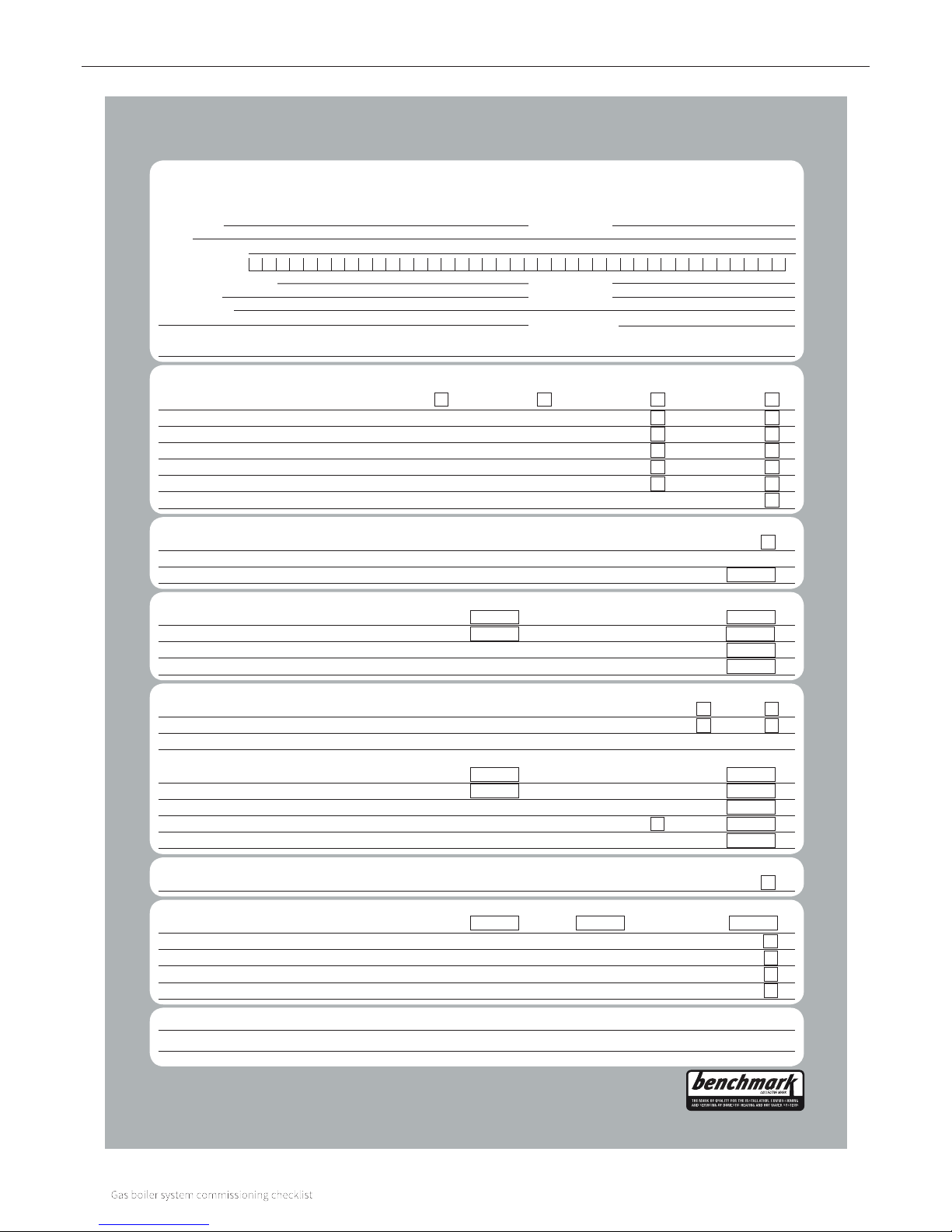
76
13 GAS BOILER SYSTEM COMMISSIONING CHECKLIST
GAS BOILER SYSTEM COMMISSIONING CHECKLIST
CONTROLS
Tick the appropriate boxes
Time and Temperature Control to Heating Room Thermostat and Programmable
Load/Weather Optimum Start
remiT/remmargorP
Room Thermostat Compensation Control
Time and Temperature Control to Hot Water Cylinder Thermostat and Programmer/Timer Combination Boiler
Heating Zone Valv se Fitted Not Required
Hot Water Zone Valv se Fitted Not Required
Thermostatic Radiator Valv se Fitted Not Required
Automatic Bypass to System Fitted Not Required
Boiler Interlock Provided
ALL SYSTEMS
The system has been flushed and cleaned in accordance with BS7593 and boiler manufacturer’s instru seY snoitc
What system cleaner was used?
What inhibitor was used? Quantity
litres
CENTRAL HEATING MODE
Measure and Record:
Gas Rate
m3/hr OR
ft
3
/hr
Burner Operating Pressure (if applicable)
mbar OR Gas Inlet Pressure mbar
Central Heating Flow Temperature
°C
Central Heating Return Temperature
°C
COMBINATION BOILERS ONLY
Is the installation in a hard water area (above 200ppm)? Yes
No
If yes, has a water scale reducer been fitted? Yes
No
What type of scale reducer has been fitted?
DOMESTIC HOT WATER MODE Measure and Record:
Gas Rate
m3/hr OR
ft
3
/hr
Burner Operating Pressure (at maximum rate)
mbar OR Gas Inlet Pressure (at maximum rate) mbar
Cold Water Inlet Temperatu er
°C
Hot water has been checked at all outlets Yes
Temperature
°C
Water Flow etaR
l/min
CONDENSING BOILERS ONLY
The condensate drain has been installed in accordance with the manufacturer’s instructions and/or BS5546/BS6798 seY
ALL INSTALLATIONS
If required by the manufacturer, record the follow OC gni
2
% OR CO ppm OR CO/CO
2
Ratio
The heating and hot water system complies with the appropriate Building Regu seY snoital
The boiler and associated products have been installed and commissioned in accordance with the manufacturer’s instru seY snoitc
The operation of the boiler and system controls have been demonstrated to and understood by the cu seY remots
The manufacturer’s literature, including Benchmark Checklist and Service Record, has been explained and left with the cu seY remots
*
dna dnalgnE ni snoitallatsni llA Wales must be notified to Local Authority Building Control (LABC) either directly or through a Competent Persons Scheme.
A Building Regulations Compliance Certificate will then be issued to the customer.
©Heating and Hotwater Industry Council (HHIC) www.centralheating.co.uk
Commi ssioning Engineer’s Signature
Customer’s Signature
(To confirm satisfactory demonstration and receipt of manufacturer’s literature)
This Commissioning Checklist is to be completed in full by the competent person who commissioned the boiler as a means of demonstrating
compliance with the appropriate Building Regulations and then handed to the customer to keep for future reference.
Failure to install and commission this equipment to the manufacturer’s instructions may invalidate the warranty but does not affect statutory rights.
Customer Name Telephone Number
Address
Boiler Make and Model
Boiler Serial Number
Commissioned by (print name) Gas Safe Number
Company Name Telephone Number
Company Address
Commissioning Date
To be completed by the customer on receipt of a Building Regulations Compliance Certificate
*
:
Building Regulations Notification Number (if applicable)
Page 77
77
14 SERVICE RECORD
SERVICE RECORD
It is recommended that your heating system is serviced regularly and that the appropriate Service Record is completed.
Service Provider
Before completing the appropriate Service Record below, please ensure you have carried out the service as described in the manufacturer’s
instructions.
Always use the manufacturer’s specified spare part when replacing controls.
SERVICE 1
Date
Energy Efficiency Checklist completed?
Yes
No
Engineer Name
Company Name
Telephone Number
Gas Safe Number
Comments
Signature
SERVICE 3
Date
Energy Efficiency Checklist completed?
Yes
No
Engineer Name
Company Name
Telephone Number
Gas Safe Number
Comments
Signature
SERVICE 5
Date
Energy Efficiency Checklist completed?
Yes
No
Engineer Name
Company Name
Telephone Number
Gas Safe Number
Comments
Signature
SERVICE 7
Date
Energy Efficiency Checklist completed?
Yes
No
Engineer Name
Company Name
Telephone Number
Gas Safe Number
Comments
Signature
SERVICE 9
Date
Energy Efficiency Checklist completed?
Yes
No
Engineer Name
Company Name
Telephone Number
Gas Safe Number
Comments
Signature
SERVICE 2
Date
Energy Efficiency Checklist completed?
Yes
No
Engineer Name
Company Name
Telephone Number
Gas Safe Number
Comments
Signature
SERVICE 4
Date
Energy Efficiency Checklist completed?
Yes
No
Engineer Name
Company Name
Telephone Number
Gas Safe Number
Comments
Signature
SERVICE 6
Date
Energy Efficiency Checklist completed?
Yes
No
Engineer Name
Company Name
Telephone Number
Gas Safe Number
Comments
Signature
SERVICE 8
Date
Energy Efficiency Checklist completed?
Yes
No
Engineer Name
Company Name
Telephone Number
Gas Safe Number
Comments
Signature
SERVICE 10
Date
Energy Efficiency Checklist completed?
Yes
No
Engineer Name
Company Name
Telephone Number
Gas Safe Number
Comments
Signature
Page 78

78
Page 79

79
Page 80

84007406
Intergas Heating Ltd
2019 Intergas Heating Ltd.
All rights reserved.
The information provided applies to the standard version of the
product. Intergas Heating Ltd can therefore not be held liable for any
damage ensuing from specifications that deviate from the standard
version of the product. Although the available information has been
composed with all possible care, Intergas Heating Ltd cannot be held
liable for any errors in the information or for the consequences of such.
Intergas Heating Ltd cannot be held liable for damage ensuing from
activities that are performed by third parties.
Subject to modifications.
Intergas Heating Limited
Unit 2
Easter Park
Worcester Road
Kidderminster
DY11 7AR
Tel: 01527 888000
Fax: 01384 279480
[email protected]
www.intergasheating.co.uk
 Loading...