

Intergas HSE–125–N/P, HSE–145–N/P, HSE-125-N, HSE-125-P, HSE-145-N User's Information Manual
...
r
USER’S INFORMATION MANUAL
Model: HSE–125–N/P, HSE–145–N/P
Gas-fired, Condensing Boiler and
Instantaneous Water Heater
Contents
Section Page
Major Components........................................................................................................................................ 2
1 About Our Manual ............................................................................................................................... 2
2 Refractory Handling............................................................................................................................. 2
3 Lighting Instructions ........................................................................................................................... 3
4 Operating Instructions ......................................................................................................................... 4
5 Inspection ............................................................................................................................................ 4
5.1 Check Area Around Appliance ............................................................................................................ 4
5.2 Check for Gas Leaks........................................................................................................................... 5
5.3 Check Venting System ........................................................................................................................ 5
5.4 Check Water System........................................................................................................................... 5
5.5 Check Pressure Relief Valves............................................................................................................. 5
5.6 Check the Condensate Drain System................................................................................................. 6
5.7 Block Venting and Heat Exchanger Safety Shutoff.............................................................................6
WARNING
If the information in this manual is not followed exactly, a fire or explosion may result
causing property damage, personal injury or loss of life.
• Do not store or use gasoline or other flammable vapors and liquids in the vicinity of
this or any other appliance.
• WHAT TO DO IF YOU SMELL GAS
- Do not try to light any appliance.
- Do not touch any electrical switch; do not use any phone in your building.
- Immediately call your gas supplier from a neighbor’s phone. Follow the gas
supplier’s instructions.
- If you cannot reach your gas supplier, call the fire department.
• Installation and service must be performed by a qualified installer, service agency o
the gas supplier.
• Improper, installation, adjustment, alteration, service or maintenance can cause
property damage, personal injury or loss of life. Read all instructions before use.
• Save this manual for future reference.
Manufacturers of Gas and Electric Boilers, Stainless Steel Tanks, Heat Exchangers and Electric Boosters.
PN7361887
94 Riverside Drive, North Vancouver, BC, V7H 2M6 • Telephone (604) 929-1214 • FAX (604) 929-5184
Allied Engineering Company
Division of E-Z-Rect Manufacturing Ltd.
HSE User’s Information Manual
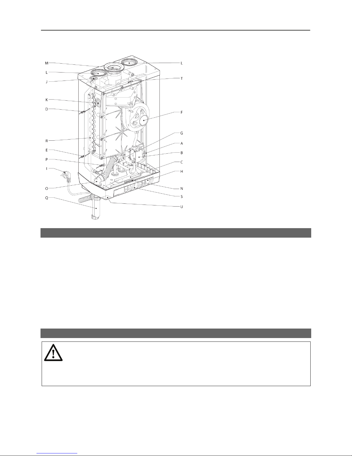
MAJOR COMPONENTS
A CH pump
B Gas valve
C Burner controller with operating panel
D Supply sensor S1
E Return sensor S2
F Blower
G DHW Flow switch
H CH Pressure gauge
I N/A
J CH manual air vent
K Sight glass and mirror for checking
flame
L Air supply
M Flue discharge
N Wiring connecting block / terminal
O Condensate discharge
P Domestic hot water sensor S3
Q Condensate trap
R Heat exchanger
S Operating and display panel
T Ionisation/ignition probe
U
Front cover fixing screw
V
High limit sensor S7 (not shown)
W
Flue sensor S8 (not shown)
About Our Manuals Section 1
Your Super Hot appliance has been provided with two manuals:
User's Information Manual - This manual is intended for the owner or user of the appliance and provides
information on routine operation and maintenance, and emergency shutdown.
Installation and Service Manual - This manual must only be used by a qualified heating installer,
service technician or gas supplier. Installation or service by anyone unqualified to do so may result in
severe personal injury, death or substantial property damage.
Both manuals should be kept in the envelope provided and affixed adjacent to the appliance so that they
are readily available for future reference. Using these manuals you can safely install and maintain this
appliance.
Refractory Handling Section 2
WARNING
The mineral block used in this product are RCFs (Refractory Ceramic Fibers).
RCFs pose a possible cancer hazard by inhalation and can cause respiratory,
skin and eye irritation. After mineral block has been fired, it will produce
increased levels of nuisance dust and poses increased carcinogenic risk.
Refractory Ceramic Fibers are contained within the combustion chamber of the heat exchanger. Only a
qualified installer or service technician should attempt to install, service or remove the boiler and must do
so following the precautionary measures described in the Installation and Service Manual.
2

Lighting Instructions Section 3
WARNING
Should appliance overheat, or the gas supply fail to shut off, do not turn off or
disconnect the electrical supply to the circulating pump. Instead, shut off the
WARNING: If you do not follow these instructions exactly, a fire or explosion may result
causing property damage, personal injury or loss of life.
gas supply at a location external to the appliance.
FOR YOUR SAFETY READ BEFORE OPERATING
A. This appliance does not have a pilot. It is
equipped with an ignition device which
automatically lights the burner. Do not
try
to light the burner by hand.
B. BEFORE OPERATING smell all around the
appliance area for gas. Be sure to smell
next to the floor because some gas is
heavier than air and will settle on the floor.
WHAT TO DO IF YOU SMELL GAS
• Do not try to light any appliance
• Do not touch any electrical switch; do
not use any phone in your building.
• Immediately call your gas supplier from
a neighbor's phone. Follow the gas
supplier's instructions.
OPERATING INSTRUCTIONS
1. STOP! Read the safety information above
on this label.
2. Turn off all electrical power to the appliance.
3. Set the room thermostat to lowest setting.
4. This appliance is equipped with an ignition
device which automatically lights the
burner. Do not
try to light the burner by
hand.
5. Turn external main manual gas shut off
valve off.
6. Wait five (5) minutes to clear out any gas.
Then smell for gas, including near the floor.
If you smell gas, STOP! Follow "B" in the
safety information above on this label. If
you don't smell gas, go to the next step.
TO TURN OFF GAS TO APPLIANCE
1. Turn off the appliance using the ON/OFF
switch on the operating panel
2. Turn off all electrical power to the appliance
if service is to be performed.
• If you cannot reach your gas supplier,
call the fire department.
C. Use only your hand to turn the manual gas
valve. Never use tools. If the valve will not
turn by hand, don't try to repair it, call a
qualified service technician. Force or
attempted repair may result in a fire or
explosion.
D. Do not use this appliance if any part has
been under water. Immediately call a
qualified service technician to inspect the
appliance and to replace any part of the
control system and any gas control which
has been under water.
7. Turn external main manual gas shut off
valve on.
8. Set room thermostat to desired setting.
9. Turn on all electrical power to the appliance.
10. If the appliance will not operate, follow the
instructions "To Turn Off Gas To Appliance"
and call your service technician or gas
supplier.
Gas Valve
OPEN
to OPEN
Gas Valve
CLOSED
to CLOSE
3. Set the room thermostat/other operation
control to lowest setting.
4. Close the external main manual gas shut off
valve.
3

HSE User’s Information Manual
Operating Instructions Section 4
Contact the installer or a qualified service technician for basic operating instructions including emergency
shutdown, filling, de-aerating and general use of the appliance. It is strongly recommended that controller
settings be adjusted by a qualified installer or service technician only.
Service and Maintenance Schedule Section 5
WARNING
The appliance must be inspected annually at the beginning of the heating
season by a qualified service technician or gas supplier’s qualified service
person. Failure to properly service and maintain the appliance (and system)
may result in severe personal injury, death, or substantial property damage.
WARNING
The owner or user should conduct a general inspection of the appliance and
system periodically throughout the year to assure safety and continued good
performance. If any problems are identified during the inspection, contact a
qualified service agency for corrective measures.
This appliance has been designed to provide years of trouble-free performance in normal installations.
The owner or user should conduct a general inspection covering all items below at the beginning of each
heating season and in mid-heating season. Notify a qualified service technician immediately if any
problems are found.
Inspection and service as specified in the Installation and Service Manual supplied with the appliance,
should be performed by qualified service technician or gas supplier’s service person at least once every
year at the beginning of the heating season for continued safe operation. This inspection must include the
main burner and heat exchanger.
Note that some operating conditions may require more frequent inspections, especially depending on
weather conditions.
Proper operation must be verified after servicing.
5.1 CHECK AREA AROUND APPLIANCE
Do not store combustible materials, gasoline, and other flammable vapours and liquids around the
appliance area.
Chemical vapors from products containing chlorine or fluorine must be avoided. Even though these
chemicals may be safe to breathe, corrosive substances (strong acids) can become liberated when they
pass through a gas flame. Even at low concentrations, these chemicals can significantly contaminate the
air supply and shorten the life of any gas-fired appliance because the acid can corrode the wall of
combustion chamber/heat exchanger, causing serious damage on heat exchanger/flue pipe and
presenting a possible of flue gas spillage or heat exchanger leakage. The following is a list of some of the
products which should be avoided:
• bleaches and chlorinated cleaning products
• paints and sprays
• water softeners (calcium or sodium chloride)
• leaking refrigeration equipment
• Freon from common aerosol dispensers
These chemicals are especially common near swimming pools, beauty shops, dry cleaning
establishments, laundry areas, workshops, and garages. Failure due to corrosion is not covered by
warranty.
4

HSE User’s Information Manual
Should your appliance be subjected to fire, flood or some other unusual condition, turn off all gas and
electrical power supply. If you are unable to turn off the gas, call your gas company or gas supplier at
once. Do not put the appliance in operation again until it has been ascertained by a qualified agency that
the controls are functioning correctly. The installer should always clearly identify the emergency shut-off
devices and make the owner aware of their location and method of operation.
WARNING
Do not use this appliance if any part has been under water. Immediately call a
qualified service technician to inspect the appliance and to replace any part of
the control system and any gas control which has been under water.
5.2 CHECK FOR GAS LEAKS
To identify gas leaks, smell for gas around the boiler area and gas piping connections. To check a
specific area, including all pipe joints connected to the gas valve, for leakage, spray a mixture of soap
and water onto the suspected area – active bubbling indicates a gas leak. The gas leaks of the joint
connected to the gas valve outlet should be checked when the appliance is on. DO NOT TEST FOR
LEAKS WITH AN OPEN FLAME. Gas leaks must be repaired immediately.
Propane or liquefied petroleum (LP) is heavier than air may collect or "pool" in a low area in the event of a
leak from defective equipment. This gas may then ignite resulting in a fire or explosion. Smell near to the
ground and low points when checking for propane gas leaks.
If you smell gas, STOP! Follow "For your safety read before operating” in Section 3.
5.3 CHECK VENTING SYSTEM
A sufficient air supply MUST be provided to this appliance. Check that the air supply inlet and vent
terminations are always kept clear of obstructions and remove any snow, ice, dust, dirt, debris, pests,
etc., which may block proper air flow.
Inspect the entire venting system, including all gaskets, to ensure the system is intact and all joints are
properly sealed. It should be continuous with no separations, leakage, obstructions, discoloration,
depressions or deformation.
5.4 CHECK WATER SYSTEMS
Avoid unnecessary replenishment of water in the CH (central heating) system. It can allow oxygen to
enter the system and cause serious corrosion problems for system components which are not anticorrosion type. As well, minerals dissolved in the water supply will precipitate when heated; minerals
preferentially deposit in the heat exchanger. Do not draw water from the central heating system for
cleaning, flushing, etc.
Any audible sounds in the appliance system may be indications of scaling or lack of sufficient water flow
and the system should be checked without delay. Scaling is due to improper maintenance. It is not the
fault of the appliance. Scale damage is not covered by warranty.
Check central heating and domestic hot water systems, including pumps, for leakage.
5.5 CHECK PRESSURE RELIEF VALVES
Pressure relief valves are installed as a code requirement. A pressure relief valve provides extra
protection against damage that could be caused by malfunctioning controls or excessive water pressure.
If a pressure relief valve on each system is not used, the warranty is void.
The pressure relief valves must be installed by a qualified installer in accordance with local codes and
should not be tampered with in any way. The outlet of the pressure relief valve should be positioned over
a suitable drain. The drain pipe must pitch down from the pressure relief valve and should be no smaller
than the outlet of the pressure relief valve. The end of the drain line should not be concealed or threaded
and should be protected from freezing. No valve of any type should be installed between the pressure
5

HSE User’s Information Manual
relief valve and unit or in the drain line. Extensive runs, traps or bends reduce the capacity of the
pressure relief valve.
Inspect the relief valves and their discharge pipes for signs of weeping or leakage. If discharge or
weeping occurs during normal operation, call a qualified technician for service. Avoid contact with the hot
water (or steam) discharged to prevent personal injury.
5.6 CHECK THE CONDENSATE DRAIN SYSTEM
WARNING
Do not operate the appliance with the condensate drain system disconnected.
If there is evidence of exhaust leakage from the condensate drain system,
turn off the appliance and contact a qualified service technician. Exhaust
leakage to the living space may result in severe personal injury, death, or
substantial property damage.
Check that the condensate trap and tube is properly connected. The
water should fill the condensate trap to form a liquid-filled trap and
must not be plugged with excessive sediment.
Check the vent hole on the top tee outlet of the condensate trap.
Make sure there are no exhaust emissions leaking from this hole.
Check the condensate drain system for water leaks
Check the level of condensate neutralization media (if used).
The above instructions also apply to a venting system equipped with
a condensation drain trap.
Figure 4 Condensate trap
5.7 BLOCKED VENTING AND HEAT EXCHANGER SAFETY SHUTOFF
This appliance is equipped with a blocked venting and heat exchanger safety shut-off control system. The
appliance will be shut down and locked out by the safety shutoff control system should the air intake and
vent outlet system become partially or completely blocked. Should this occur do not attempt to re-light the
appliance. Contact a qualified service technician to re-light the appliance.
6
 Loading...