

Intergas Compact HRE18 SB (G.C. 41-291-01), 24 SB (G.C. 41-291-02), 30 SB (G.C. 41-291-03), 40 SB (G.C. 41-291-07 ) Installation, Service And User Instructions Manual
Intergas Heating Ltd 1
Compact HRE
18 SB
(G.C. 41-291-01)
24 SB
(G.C. 41-291-02)
30 SB
(G.C. 41-291-03)
40 SB
(G.C. 41-291-07 )
Installation, service
and user instructions
Please read these installation instructions carefully before installing and using
the appliance. Keep these installation instructions with the appliance.
Always act in accordance with the instructions indicated.

Intergas Heating Ltd 2
Benchmark places responsibilities on both manufacturers and installers. The purpose is to ensure that customers are provided with the correct
equipment for their needs, that it is installed, commissioned and serviced in accordance with the manufacturer’s instructions by competent
persons and that it meets the requirements of the appropriate Building Regulations. The Benchmark Checklist can be used to demonstrate
compliance with Building Regulations and should be provided to the customer for future reference. Please read the Benchmark Checklist
carefully, page 50, and complete all sections, as required by law, relevant to the appliance and installation. The details within the Checklist will be
required in the event of any warranty work. On completion the Checklist must be left with the end user. The relevant sections of the Service
Record, page 51, must be completed on each subsequent Service visit.
Installers are required to carry out installation, commissioning and servicing work in accordance with the Benchmark Code of Practice which is
available from the Heating and Hotwater Industry Council who manage and promote the scheme. Visit www.centralheating.co.uk for more
information.
CONTENT
1
Preface 4
1.1 Regulation ........................................................................................................................................................................................ 4
1.2 Warnings .......................................................................................................................................................................................... 4
1.3 Manual handling .............................................................................................................................................................................. 4
1.4 Warnings on the box ........................................................................................................................................................................ 4
1.5 Pictograms ....................................................................................................................................................................................... 4
1.6 Abbreviations and descriptions used ............................................................................................................................................... 5
1.7 This manual ..................................................................................................................................................................................... 5
1.8 Service and technical support ......................................................................................................................................................... 5
1.9 Product identification ....................................................................................................................................................................... 5
2
Safety regulations 6
2.1 General ............................................................................................................................................................................................ 6
2.2 The Installation ................................................................................................................................................................................ 6
2.3 Approvals ......................................................................................................................................................................................... 7
2.4 Technical data ................................................................................................................................................................................. 8
2.5 Product FICHe according to CELEX-32013R0811, ANNEX iV ....................................................................................................... 9
2.6 Components .................................................................................................................................................................................. 10
3
General boiler information 11
3.1 General .......................................................................................................................................................................................... 11
3.2 Boiler controller .............................................................................................................................................................................. 11
3.3 Parameter list................................................................................................................................................................................. 11
3.4 Heat transfer .................................................................................................................................................................................. 11
3.5 Central heating system/automatic by-pass .................................................................................................................................... 11
3.6 Room temperature control ............................................................................................................................................................. 11
3.7 Integrated clock ............................................................................................................................................................................. 11
4
Operation 12
4.1 General .......................................................................................................................................................................................... 12
4.2 Central heating mode .................................................................................................................................................................... 12
4.3 Operating modes ........................................................................................................................................................................... 12
4.4 Clock function (heat only) .............................................................................................................................................................. 13
4.5 PC Interface ................................................................................................................................................................................... 13
4.6 Test programs................................................................................................................................................................................ 14
4.7 Frost protection ............................................................................................................................................................................. 14
5
Installer important points 15
6
Accessories 16
7
Installation 18
7.1 Overall dimensions ........................................................................................................................................................................ 18
7.2 Installation location ........................................................................................................................................................................ 19
7.3 Assembly ....................................................................................................................................................................................... 20
7.4 Installing the appliance .................................................................................................................................................................. 21
8
Connection 22
8.1 Connecting CH installation ............................................................................................................................................................ 22
8.2 Electrical connection ...................................................................................................................................................................... 23
8.3 Condensate disposal ..................................................................................................................................................................... 25
8.4 Flue System ................................................................................................................................................................................... 26

Intergas Heating Ltd 3
9
Commissioning the appliance 29
9.1 Filling and venting the appliance and the installation .................................................................................................................... 29
9.2 Commissioning the appliance ....................................................................................................................................................... 31
9.3 Setting and adjusting the clock functions ...................................................................................................................................... 32
9.4 Additional functions ....................................................................................................................................................................... 32
9.5 Shutting down ................................................................................................................................................................................ 33
10
Setting and adjustment 34
10.1 Directly via the operating panel ..................................................................................................................................................... 34
10.2 Setting via the service code .......................................................................................................................................................... 35
10.3 Parameters .................................................................................................................................................................................... 35
10.4 Weather– compensation adjustment ............................................................................................................................................. 36
10.5 Setting maximum CH power .......................................................................................................................................................... 37
10.6 Adjusting pump setting .................................................................................................................................................................. 37
10.7 Gas-Air ratio control ...................................................................................................................................................................... 38
10.8 Checking the gas air ratio control .................................................................................................................................................. 39
10.9 Conversion to different gas type.................................................................................................................................................... 43
11
Faults 44
11.1 Fault codes .................................................................................................................................................................................... 44
11.2 Other faults ................................................................................................................................................................................... 45
12
Maintenance 48
12.1 Disassembly .................................................................................................................................................................................. 48
12.2 Cleaning ........................................................................................................................................................................................ 48
12.3 Assembly ....................................................................................................................................................................................... 49
12.4 Combustion ................................................................................................................................................................................... 49
13
Electrical diagram 50
13.1 Electrical diagram HRE SB ........................................................................................................................................................... 50
13.2 NTC resistances ............................................................................................................................................................................ 50
13.3 Typical Y Plan connection ............................................................................................................................................................. 51
13.4 Typical S Plan connection. ............................................................................................................................................................ 51
14
Short spares list 52
15
Warranty conditions 53
16
CE declaration 53
17
Gas boiler system commissioning checklist 54
18
Service record 55
© 2015 Intergas Heating Ltd. All rights reserved.
The information provided applies to the standard version of the product. Intergas Heating Ltd cannot therefore be held liable for any loss or damage arising from product
specifications deviating from the standard version. The available information has been compiled with all possible care, but Intergas Heating Ltd cannot be held liable for
any errors in the information or for the consequences thereof.
Intergas Heating Ltd cannot be held liable for any loss or damage arising from work performed by third parties.
Subject to change.
Intergas Heating Ltd 4
1 PREFACE
1.1 Regulation
The Intergas boiler meets the requirements of Statutory Instrument 'The Boiler (Efficiency)
Regulations' and is deemed to meet the requirements of:
•
Gas Appliance Directive 90/396/EEC
•
Boiler Efficiency Directive 92/42/EEC
•
Low Voltage Directive 2006/95/EC and
•
Electromagnetic Compatibility Directive 2004/108/EC
Intergas declares that the materials used in the manufacturing of this appliance are nonhazardous and that no substances harmful to health are contained within the appliance.
1.2 Warnings
Intergas accepts no responsibility for the unsatisfactory performance of the appliance or flue
arising from the failure to comply with the installation and user instructions. Incorrect installation
could invalidate your guarantee and may lead to prosecution.
If the appliance is re-sold or installation transferred the appliance must be re-registered with
Intergas in order to maintain the warranty.
The boiler must be installed in accordance with these instructions and the regulations currently
in force. Read these instructions carefully before installing or using the appliance.
1.3 Manual handling
When moving the boiler always keep your back straight, bend your knees, don’t twist, move
your feet. Avoid bending forwards or sideways and keep the load as close to your body as
possible. Where possible transport the boiler using a suitable trolley, sack truck or get some
assistance. Grip the boiler firmly and before lifting establish where the weight is concentrated to
determine the centre of gravity, repositioning yourself if necessary.
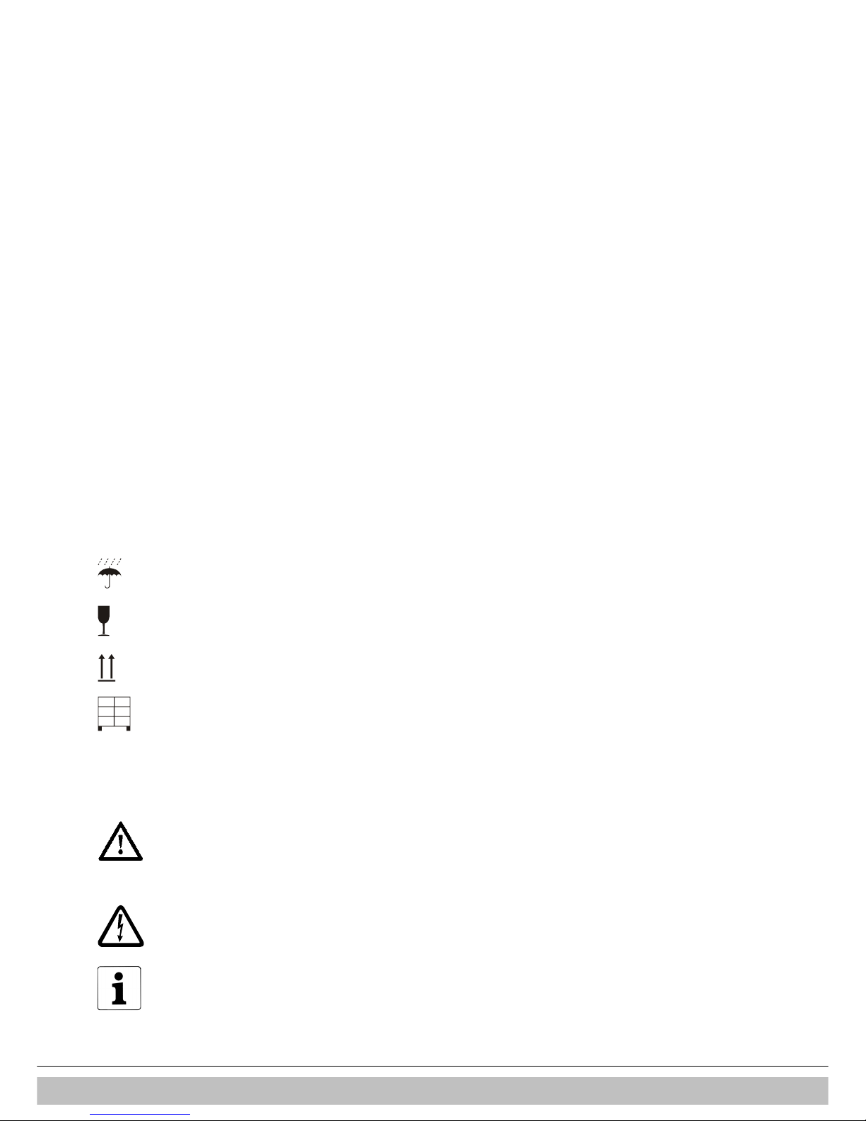
1.4 Warnings on the box
This is a fragile piece of equipment: Please provide a dry
storage for the appliance.
This is a fragile piece of equipment: Please be very careful
not to drop.
Store the appliance upright as indicated on the box.
No more than three boxes should be stacked on top of each
other.
1.5 Pictograms
The following pictograms are used in this manual:
CAUTION
Procedures which – if they are not performed with the
necessary caution – can result in damage to the product, the
surrounding area or the environment, or in physical injury.
WARNING HIGH VOLTAGE
Risk of electrical shock.
NOTE
Important information regarding the correct usage or
installation of the appliance.
Intergas Heating Ltd 5
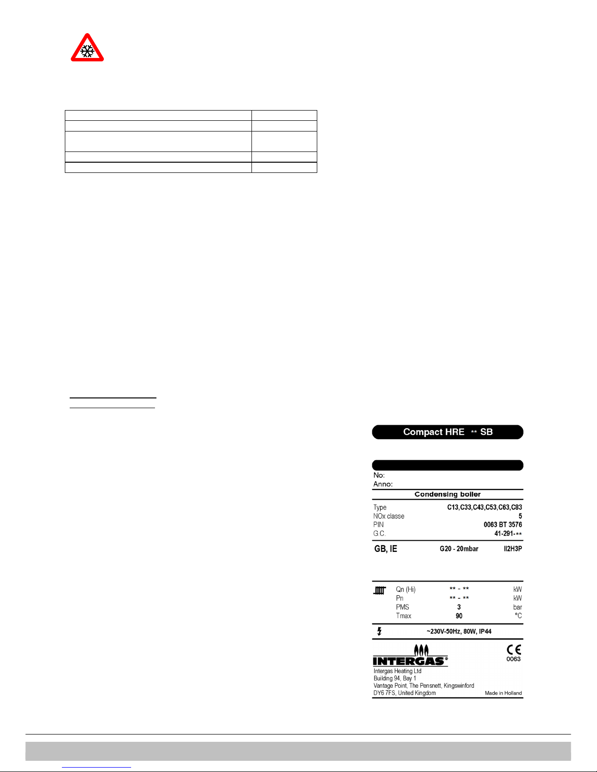
FROST PROTECTION
Procedures which must be followed to prevent frost
damage.
1.6 Abbreviations and descriptions used
Description Referred to as
High efficiency HE
Intergas Compact HRE SB wall mounted gas fired
boiler
Appliance
Appliance plus pipe work for central heating CH installation
Appliance plus pipe work for domestic hot water DHW installation
1.7 This manual
This manual will enable you to assemble, install and maintain the appliance safely. Follow the
instructions carefully. In case of doubt contact the manufacturer. Keep these installation
instructions with the appliance.
1.8 Service and technical support
For information about specific adjustments, installation, maintenance and repair work, please
contact:
Intergas Heating Ltd
Building 94, Bay 1 Vantage Point
The Pensnett Estate
Kingswinford
West Midlands
DY6 7FS
Tel: 01527 888000
Fax: 01384 279480
info@intergasheating.co.uk
www.intergasheating.co.uk
1.9 Product identification
You will find the appliance data on the data plate on the underside of the appliance.
• Model
• G.C. registration number
• Heat input (net) [kW]
• Heat output CH [kW]
• Appliance category
• Gas type
• Gas supply pressure [mbar]
• NOx class
• Appliance type
• Maximum CH pressure [bar]
• Electrical supply
• Protection
• PIN
• Serial number
• Production year

Intergas Heating Ltd 6
2 SAFETY REGULATIONS
The manufacturer Intergas Heating Ltd accepts no liability whatsoever for damage or injury
caused by failure to adhere (strictly) to the safety regulations and instructions, or
carelessness during installation of the Intergas Compact HRE SB High Efficiency wall
mounted gas fired boiler and any associated accessories.
2.1 General
It is law that all gas appliances are installed by a Gas Safe registered competent engineer
and in accordance with the following recommendations:
•
Current Gas Safety (Installation and Use) Regulations
•
All current building regulations
•
Building Standards (Scotland) Consolidated
•
This appliance must be installed in accordance with the Gas (Safety and Use) Regulations,
current Building Regulations, Building Standards (Scotland), I.S.813 Installation of Gas
Appliances (Ireland), IEE Wiring Regulations (BS 7671), Health and Safety Document No.
635 (Electricity at Work Regulations) and Local Water Authority Bye Laws
•
UK Water Regulations and Bye Laws
•
Health & Safety
2.2 The Installation
The installation must comply with the following British Standards codes of practice:
•
BS 5440: Flues and Ventilation for gas appliances of rated input not exceeding 70kW (Part 1
Flues)
•
BS 5440: Flues and Ventilation for gas appliances of rated input not exceeding 70kW (Part 2 Air
Supply)
•
BS 5546: 2000 Installation of gas hot water supplies for domestic purposes.
•
BS 5549: 1990 Forced circulation hot water systems
•
BS 6700: 1997 Design, Installation, testing and maintenance of services supplying hot water
•
BS 6798: 2000 Specification for installation of gas fired hot water boilers of rated input not
exceeding 70kW
•
BS 6891: 1998 Installation of low pressure gas pipe-work installations up to 35mm (RI)
•
BS 7593: 1992 Code of practice for treatment of water in heating systems
•
BS 7671: 2001 Requirements for electrical installations, IEE Wiring regulations
Reference should also be made to:
•
Guide to condensing boiler installation assessment procedures for dwellings
•
The institute of Gas Engineers document IGE/UP/7 for timber frame dwellings

Intergas Heating Ltd 7
2.3 Approvals
Natural Gas
Intergas Compact HRE SB Pre-mix Condensing System Boiler
British Gas Service Listing:
Compact HRE 40 SB G.C.N. 41-291-07
Compact HRE 30 SB G.C.N. 41-291-03
Compact HRE 24 SB G.C.N. 41-291-02
Compact HRE 18 SB G.C.N. 41-291-01
Notified /Body
The Intergas Compact HRE SB range of central heating boilers are manufactured from high
quality materials and designed for reliability and optimum performance.
Intergas is committed to the continual development of their appliances and reserves the right
to make changes without notification to ensure their customers benefit from the latest
advances in combustion technology and energy conservation.
Gastec 0063PT3576 Directive 90/396/EEC
Directive 92/42/EEC
Intergas Heating Ltd 8
2.4 Technical data
Appliance category C13; C33; C43; C53; C83
Gas supply pressure 20 mbar -G20 ; 37 mbar – G31
Gas Category II2H3P
Technical data Compact HRE 18 SB 24 SB 30 SB 40 SB
Gas Council number G.C. 41-291-01 G.C. 41-291-02 G.C. 41-291-03 G.C. 41-291-07
CH
Nom. Input rating (lower value)* kW 5.6 – 18.7 7.1 – 23.7 7.6 – 27.0 7.8 – 42.5
Rated power* kW 6.1 – 18.2 7.7 – 23.1 8.2 – 26.6 8.4 – 40.9
Max. CH water pressure bar 2.5 2.5 2.5 2.5
Max. CH water temperature °C 90 90 90 90
Other data
Gas consumption (G20) m3/h 0.58 – 2.29 0.75 – 2.91 0.79 – 3.39 0.80 – 4.41
Gas consumption (G31) m3/h 0.22 – 0.87 0.28 – 1.11 0.30 – 1.29 0.31 –1.68
Appliance pressure loss (CH) mWk See § 10.5 See § 10.5 See § 10.5 See § 10.5
NOx class natural gas 5 5 5 5
NOx class LPG 5 4 5 5
Electrical data
Mains power V 230 230 230 230
Safety class IP IP44 IP44 IP44 IP44
Power consumption : full load W 80 80 80 135
Power consumption: standby W 2 2 2 2
Boiler dimensions and weight
Height mm 590 650 710 710
Width mm 450 450 450 450
Depth mm 240 240 240 240
Weight kg 30 33 36 36
We have a policy for continual improvement and development, therefore we reserve the right to change specifications without prior notice.

Intergas Heating Ltd
9
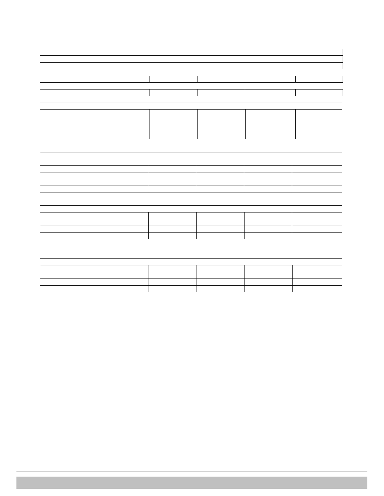
2.5 Product FICHe according to CELEX-32013R0811, ANNEX iV
Supplier Intergas Heating Ltd
Building 94, Bay 1 Vantage Point
The Pensnett Estate
Kingswinford
West Midlands
DY6 7FS
Type designation Symbol Unit Compact HRE
18 SB 24 SB 30 SB 40 SB
Seasonal space heating energy
efficiency class
- - A A A A
Heat rated output
(power)
P
rated
kW 18 23 27 41
Seasonal space heating energy
efficiency
ηS % 93 93 93 92
Annual energy consumption QHE GJ 55 69 80 125
Sound power level LWA dB 45 45 50 55
CAUTION
• Please read all instructions before fitting this appliance.
• This appliance is not intended for use of persons (including children) with diminished physical, sensory or mental
ability, or lack of experience and knowledge, unless supervised by, or instruction about the use of the appliance by a
person who is responsible for their safety.
• The appliance and installation should every year be inspected by an qualified installer and cleaned when necessary.
See annual cleaning § 12
• The appliance can be cleaned with a damp cloth. Don’t use aggressive or abrasive cleaning- or solvent products.

Intergas Heating Ltd 10
2.6 Components
A. CH pump K. Sight glass
B. Gas valve L. Air supply cap
C. Boiler controller M. Flue pipe adapter (only to be used in combination with the
accompanying elbow in flue sets).
D. Sensor S1 N. Connection block / terminal strip X4
E. Sensor S2 O. Condensate drain pan
F. Fan P. N.a.
G. N.a. Q. Condensate trap
H. CH pressure sensor R. Heat exchanger
I. Mains lead 203 V AC without plug (stripped) S. Operating panel and read-out
J. Manual air bleed T. Ionisation / ignition electrode
U. Position of data plate

Intergas Heating Ltd
11
3 GENERAL BOILER INFORMATION
3.1 General
The Intergas Compact HRE SB wall mounted, gas fired boiler is a closed appliance.
The appliance is intended to transfer heat to the water circuit in a CH system and when
an indirectly heated domestic hot water (DHW) storage cylinder is installed, apply heat
to the DHW installation.
The air supply and combustion gas flue connection is as standard prepared for a
concentric 60/100 horizontal flue system. The appliance can be connected to a wall
mounting jig and expansion vessel. The appliance can also be connected without the
wall mounting jig using the robo kit.
The Intergas Compact HRE SB wall mounted gas fired boiler carries the CE rating and
IP44 electrical protection.
The appliance is supplied as standard for natural gas (G20). For usage of propane gas
(G31) the boiler can be modifed by changing the gas injector. A gas conversion kit can
be ordered at Intergas Heating Ltd.
NOTE
Modification of the boiler can only be done by a qualified
competent person.
3.2 Boiler controller
An electronic control unit, consisting of a boiler controller and separate ignition module
which is placed on the gas valve, provides direct burner ignition and flame supervision
along with continuous modulation of the burner’s gas supply.
3.3 Parameter list
All boiler adjustments are accessible through the parameter list in the software.
3.4 Heat transfer
Heat transfer to the boiler’s heating circuit is obtained via a primary, gas to water heat
exchanger within a hermetically sealed combustion chamber. A modulated speed fan
blows the gas/air mixture into the combustion chamber and expels the products of
combustion to outside air via an associated flue system.
3.5 Central heating system/automatic by-pass
An integral pump located in the boilers hydraulic circuit circulates water through the
heat exchanger to the central heating circuit. In the event of reduced or interrupted
water circulation in the central heating circuit, an automatic system by-pass should be
fitted as far away from the boiler as possible.
Note
It is no longer permissible to utilize a non-thermostatic controlled radiator as a by-pass.
3.6 Room temperature control
Room temperature can be controlled by the use of an external room thermostat and
thermostatic radiator valves.
Note
Connection of the room thermostat is dependant on the operating voltage of the
thermostat.
3.7 Integrated clock
The boiler incorporates an integrated clock, which allows the setting of central heating
periods (See the User Instructions, ‘Operation and display read-out’ for details) and the
boiler’s control panel incorporates an LED display, which indicates the state of
operation and fault defect codes.
Note
For S and Y plans set integral clock to C-ON and fit an external timer/programmer.

Intergas Heating Ltd 12
4 OPERATION
4.1 General
The Intergas Compact HRE SB wall mounted, gas fired system boiler is a modulating
high efficiency boiler. This means that the power is adjusted in line with the desired heat
requirement.
The appliance is equipped with an electronic boiler controller which, each time heat is
requested from the heating supply, starts the fan, opens the gas valve, ignites the
burner and continuously monitors and controls the flame, depending on the requested
output.
4.2 Central heating mode
When a heating demand is requested (power is on, the timer and thermostat are calling for
heat) the integral pump is energised and the boiler will fire automatically. The hot water is
now circulated around the central heating system. When the end of the central heating
demand is reached (the thermostat reaches temperature or the time clock reaches the end of
its set period) the burner will shut down while the pump remains functioning during a preset
period of time to dissipate any excess heat from within the boiler’s heat-exchanger. After that
the boiler will revert to stand-by, waiting to respond to the next heating demand.
4.3 Operating modes
A code on the service display of the operating panel indicates the appliance’s operating
mode.
-
Off
The appliance is out of operation but is supplied with electrical power. No response
occurs to calls for DHW or CH. The appliance frost protection is active. This means that
the pump operates and the exchanger is heated up if the temperature of the water
present in it falls too far.
If the frost protection is actuated, code
7
is displayed (heating the exchanger).
In this operating mode the pressure in the CH installation (in Bar) can also be read on
the temperature display.
Waiting mode
The LED at the button is lit and possibly one of the LEDs for the DHW comfort
function. The appliance is ready to respond to a request for CH of DHW.
0
Pump overrun of CH
After the end of CH operation the pump continues to run. The running time is factory set at
the value in accordance with § 10.3. This setting can be changed.
In addition, the pump runs automatically for 10 seconds once every 24 hours in order to
prevent seizing. This automatic switching on of the pump occurs at the time of the last call for
heat. To change the time, the room thermostat setting should be increased briefly at the
desired time.
1
Boiler shutdown when required temperature reached
The boiler controller can temporarily shut down the request for heat. The burner is then
stopped. Shutdown occurs because the requested temperature has been reached.
When the temperature has fallen sufficiently and the anti cycle time has passed the
shutdown is cancelled.
2
Self-test
The connected sensors are checked regularly by the boiler controller. During the check
the boiler controller does not perform any other tasks.
3
Ventilation
When the appliance is started the fan is first brought to starting speed. When the
starting speed has been reached the burner is lit. Code 3 is also visible when post-
ventilation is taking place after the burner has stopped.
4
Ignition
When the fan has reached the starting speed, the burner is ignited by means of
electrical sparks. During ignition the code
4
is visible. If the burner does not ignite, a
new ignition attempt occurs after approximately 15 seconds. If after 4 ignition attempts
the burner is not yet burning, the boiler controller goes into fault mode (See § 11.1 ).

Intergas Heating Ltd
13
5
CH operation
An on/off thermostat, an OpenTherm thermostat, an external sensor or a combination of
the latter can be connected to the boiler controller.
When a request for heat is received from a thermostat, the fan is started (code 3 ),
followed by ignition (code
4
) and CH operating mode (code 5 ).
During CH operation the fan speed and hence the appliance power are controlled by
the boiler controller so that the CH water temperature reaches the desired CH supply
temperature.
If an on/off thermostat is connected, this is the CH supply temperature set on the
display. In the case of an OpenTherm thermostat the desired CH supply temperature is
determined by the thermostat. In the case of an external sensor the desired CH suppply
temperature is determined by the heating line programmed in the boiler controller. For
the latter two, however, the maximum is the temperature set on the display.
During CH operation the requested CH supply temperature is indicated on the operating
panel.
The CH supply temperature can be set between 30°C and 90°C.
4.4 Clock function (heat only)
The boiler is equipped with a digital clock and offers the possibility to program 4 points in time
to switch from CH off or CH on.
During the “clock active” periods the boiler will respond on CH demands from the room
thermostat. During the “clock inactive” periods the boiler will not respond on CH demands.
N.B. The clock function is only applicable when using the boilers as “heat only”. When using the
boiler in combination with an external DHW tank, for example in an S or Y plan wired installation
the clock must be set to C-on.
Additionally the following special modes can be chosen:
1. t-on (temporary on).
The boiler will respond to every CH demand from the room thermostat until the next switch
moment.
2. c-on (continuous on).
The boiler will respond to every CH demand from the room thermostat without any time limit.
3. OFF.
The boiler will not respond to any CH demand from the room thermostat.
NOTE
For setting and adjusting the clock see § 9.3 Setting and adjusting the clock
functions.
4.5 PC Interface
The boiler controller is equipped with an interface for a PC, which can be connected by
means of a special cable and associated Intergas Diagnostic Software (IDS). This
facility allows the behaviour of the boiler controller, the appliance and the heating
installation to be monitored over a longer period.

Intergas Heating Ltd 14
4.6 Test programs
The boiler controller has a facility for placing the appliance in test mode. Activation of a
test program will result in the appliance starting operation at a fixed fan speed, without
the control functions being actuated. The safety functions do remain active. The test
program is ended by pressing the and simultaneously or will end automaticaly
after 10 minutes.
Test programs
Program description Button
combinations
Display reading
Burner on at minimum power and “L”
Burner on with maximum CH power
setting (See § 10.3, parameter 3)
and (1x) “h”
Burner on with maximum DHW power
(See § 10.3, parameter 4)
and (2x) "H"
Switch off test program and Actual situation
Addition readings :
During test mode the following data can be read :
•
By pressing the button continuesly in the display the CH water pressure is shown.
•
By pressing the button continuesly in the display the ionisation current is shown.
4.7 Frost protection
FROST PROTECTION
To prevent freezing the appliance is equipped with an internal frost
protection. If the heat exchanger temperature falls too low, the burner
switches on and the pump runs until the heat exchanger temperature
is sufficient. When the appliance frost protection is activated the
symbol code
7777
is displayed (pre heating the heat exchanger).
If the installation (or a part of it) is in danger of freezing, an (external)
frost thermostat must be fitted to the return line at the coldest location.
This must be connected in accordance with the wiring diagram
(See § 8.3).
NOTE
If the appliance is out of operation (
-
on the service display) the appliance’s
internal frost protection is still active. However, there will be no response to a
heating demand from an (external) frost thermostat.

Intergas Heating Ltd
15
5 INSTALLER IMPORTANT POINTS
Please read all instructions before fitting this appliance
•
The installer shall instruct the user on the operation of the boiler, safety devices
contained within the boiler and on the location of the filling loop and how to re-pressurise
the system if the water pressure falls.
•
The installer should then hand over the instructions indicating the included Benchmark
Commissioning Checklist that has been completed.
•
It is required under Gas Safe Regulations for the installation to be notified to Building
Control (Gas Safe Notifcation).
•
Before proceeding to commission the boiler check the gas inlet pressure is 20mbar (NG)
or 37mbar for Propane.
•
Combustion analysis with a correctly calibrated and certificated analyser is essential for
safe commissioning of the boiler.
•
A pressure reducing valve set to 3.5 bar must be fitted if supply mains pressure is above
4 bar.
•
A suitable scale reducer must be fitted if water hardness is above 200 ppm.
•
The user should be instructed to keep the instructions in a safe place for servicing and
future reference.
•
It is important to keep the boiler clear of dust during the installation. In particular, do not
allow debris to enter the flue connection at the top.
•
Before fitting the boiler ensure that the pipe work that you are installing is connected to
the appropriate connections on the boiler.
It is important to thoroughly flush the water circuits, after isolating the boiler, in order to
remove any fluxes and debris from them. This should be done particularly where boilers
are being fitted to existing radiator circuits (please refer to current Standard Codes of
Practice).
•
BS 7593:2006 for the details to clean DHW and Central heating system.
•
This boiler has been factory set but adjustment may be required to the heating input in
order to match the individual heating demand. This can be done by changing parameter
3 (= max. power CH) or parameter 4 (= max. power domestic water).
•
Please do not use the pressure relief valve as a means of flushing the system.
•
Remember that after hot water draw of a possible delay may occur before the heating
system will fire up.
•
All fluxes, residues and cleaner must be flushed from pipe-work and radiators prior to
commissioning.
•
External expansion vessels are best connected water side downwards to allow correct
draining/cleaning of system and to prolong the life of the vessel diaphragm.
•
Note: an anti-cycle delay time can be set up to a maximum of 15 minutes by adjusting
parameter P as described in § 10.3.
•
If you experience any problems please refer to the installation and commissioning
guidelines within the boiler instruction manual. If necessary, please contact Intergas
Heating Ltd (See § 1.8).
Remember it is a requirement to complete the Benchmark code of practice logbook before
leaving the installation. You are also required to register the boiler through the Gas Safe
registration scheme.
Intergas Heating Ltd 16
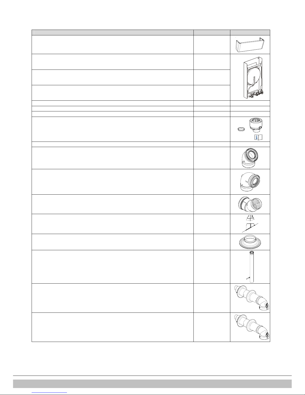
6 ACCESSORIES
Description Article number
Pipe cover set (incl. mounting material) 093217
Wall mounting jig + exp. vessel 8 litres HRE SB 30 & SB 40
093207
Wall mounting jig + exp. vessel 8 litres HRE SB 24
093197
Wall mounting jig + exp. vessel 8 litres HRE SB 18
093187
Outside sensor 203207
DHW storage cylinder sensor 065117
Diverter valve 230 V 092647
Concentric connection (boiler adapter) Ø60x100
•
Concentric flue adapter
•
Sealing cap
Neccesary when connecting to a higher positioned wall terminal
090547
Sampling cap 847000
Bend 45° 084661
Bend 90° 084660
Deflector kit 081295
Weather slate (steep roof) 087910
Weather slate (flat roof) 087372
Extension L=100 incl. wall bracket 082975
Horizontal straight wall terminal extended
Only to be used in combination with the base adapter on the boiler
082980
Horizontal telescopic wall terminal
Only to be used in combination with the base adapter on the boiler
081297
Intergas Heating Ltd
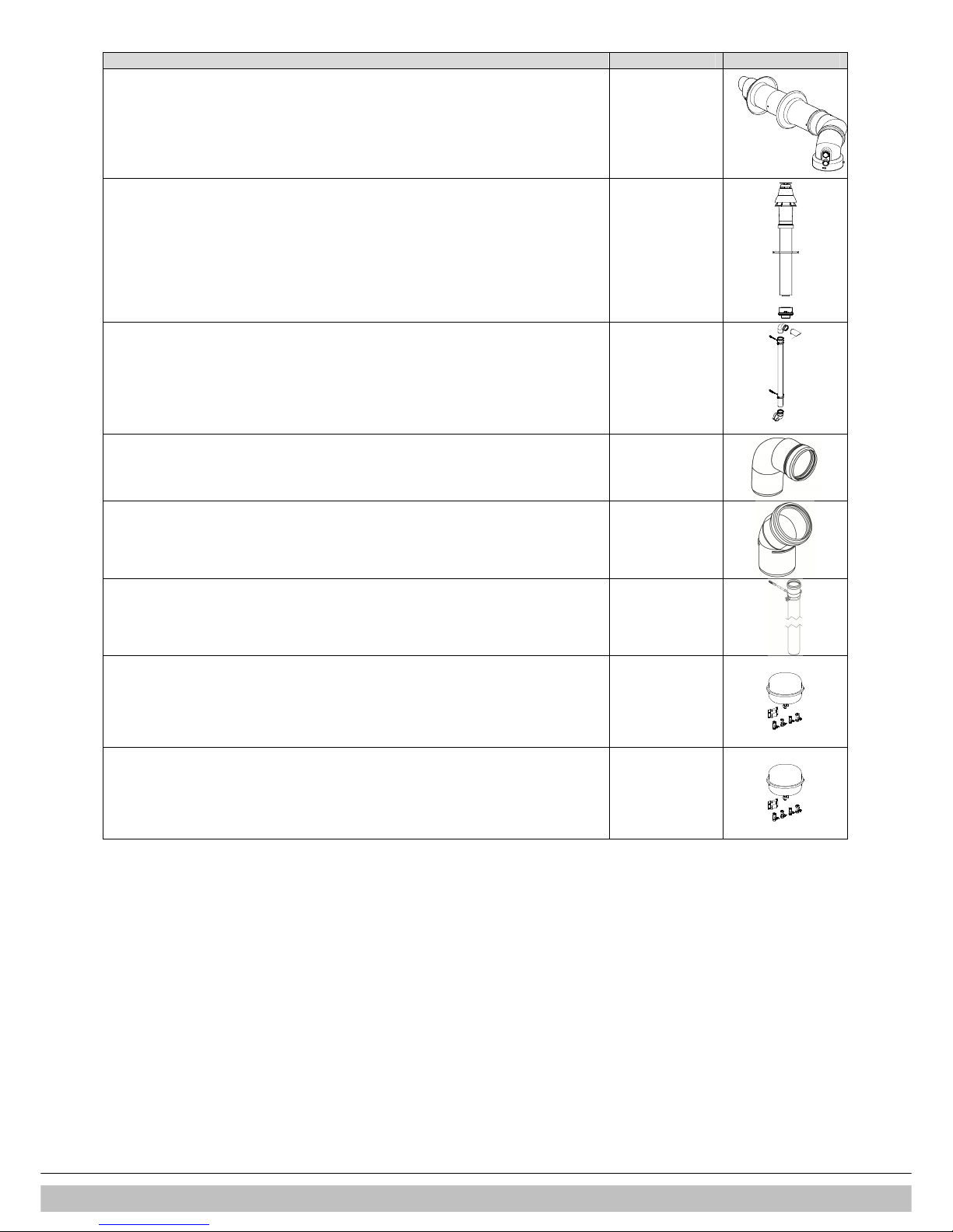
17
Description Article number
Horizontal telescopic offset wall terminal
Only to be used in combination with the base adapter on the boiler
081298
Vertical roof terminal
(incl. boiler adapter 60/100)
082973
Plume management kit
081294
Elbow 90° ((for Plume management kit)
081284
Elbow 60° (for Plume management kit)
081285
Extension L=100 incl. wall bracket (for Plume management kit)
081286
Robo kit 12 litres
090000
Robo kit 8 litres
090100
 Loading...