

Interfire D900.1, D1700.1, D3000.1 Instruction Manual
MONO CHANNEL CLASS "D"
AUTOMOTIVE AMPLIFIER
INSTRUCTION MANUAL
D900.1 / D1700.1 / D3000.1


PLEASE READ ALL INSTRUCTIONS BEFORE INSTALLATION !
free installation.
CONGRATULATIONS ON YOUR PURCHASE
Your new high fidelity mono block amplifier is designed to deliver maximum enjoyment
and one year of trouble free service. Please take a few moments to read this manual
thoroughly. It will explain the features and operation of your unit and help insure trouble
FEATURES
• Class ''D'' Technology
• 1 Ohm Stable
• Spec Audiophile Grade Components
• High Efficiency PWM Power Supply
- Multi-stranded power toroid
- Tow toroidal core
- MOSFET transistors
• Oversized Capacitor Banks
• Discrete Mount Power and speaker terminals
• Variable Low Pass Electronic Crossover 50Hz - 250Hz
• Built in power bridging module
• Circuit / Thermal / Overload Protection
• Remote Level Control
IMPORTANT
The quality of installation may affect the performance and reliability of your product. If
you have any doubts or questions regarding installation, you may wish to contact your
authorized dealer. Remember to heed all wire and fuse requirements suggested in this
manual. Warranty may be void if proper installation technique is not used (refer to warranty
section in the rearof the manual )
1
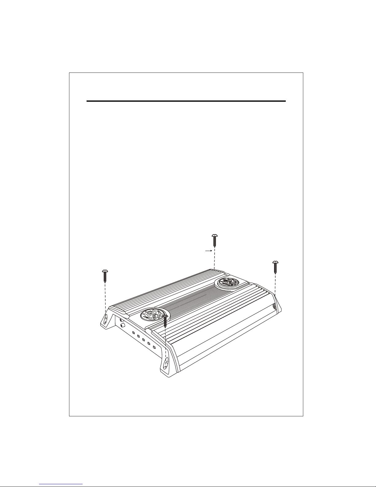
INSTALLATION
1. After reading precaution, decide where you are going to install the unit. Also, see Fig.1.
2. Once the location has been determined, place the amplifier into position. Using a felt tip
pen or pencil mark the four holes to be drilled for mounting. NEVER use the amplifier as
a template for drilling. It is very easy to damage the amplifier surface in this manner.
3. Remove amplifier. Drill four 3.5 m/m holes into mounting surface. If you want to mount
4. If possible, test the system to ensure it is operating correctly before final mounting of
5.
INSTALLATION DIAGRAM
FIG.1
2
Self Tapping Screws
MOUNTING:
Mount the amplifier using the supplied 4 self tapping screws.
the amplifier to MDF or wood panel, drill four 3.0m/m diameter holes into mounting surface.
the amplifier.
POWER
GND+12V REM
ON
PROTECT
SPEAKER FUSE
POWER
GND+12V REM
ON
PROTECT
SPEAKER FUSE
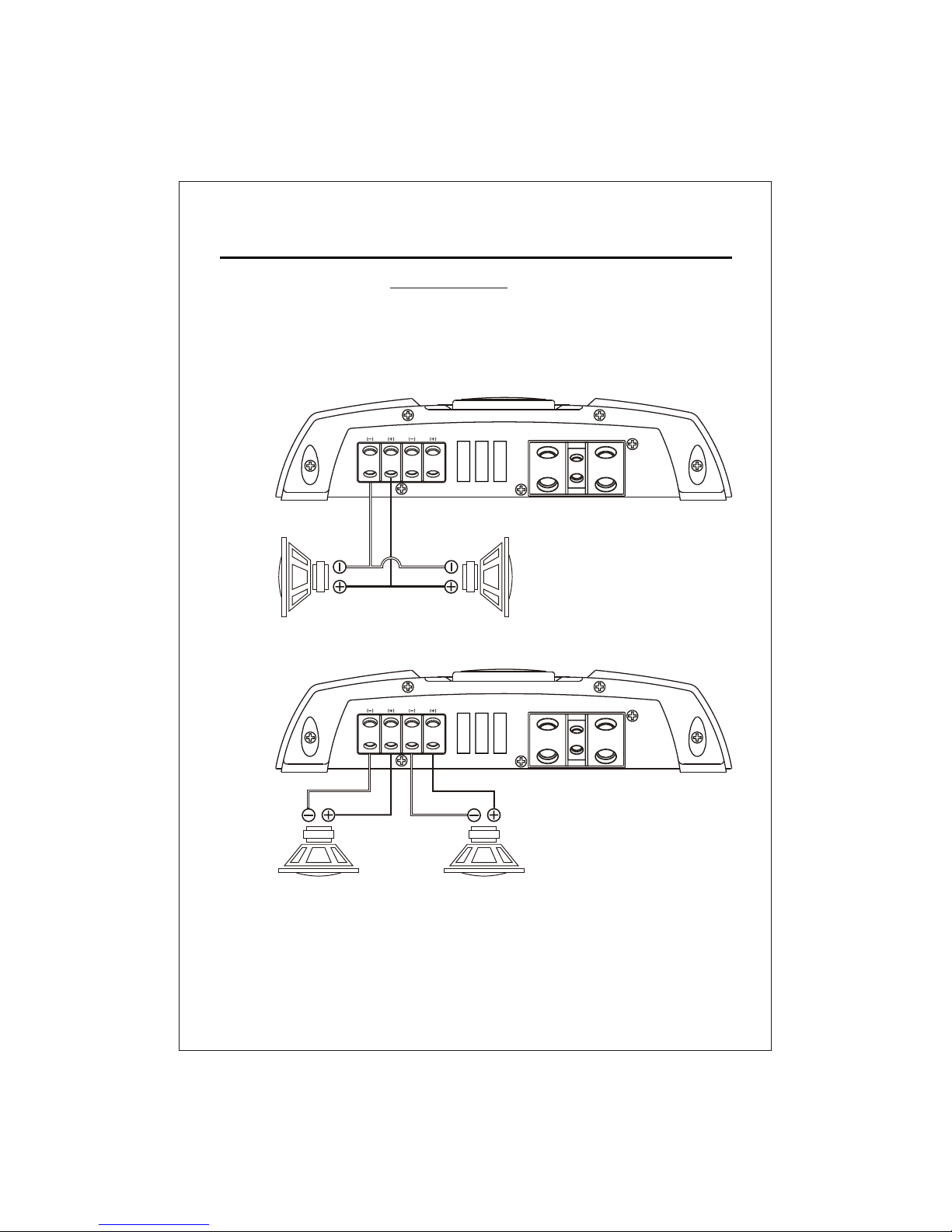
The Class "D" amplifier is a SINGLE CHANNEL dedicated subwoofer amplifier. Unlike
other amplifiers, the Class "D" operates as a single channel and cannot be bridged.
Don't be fooled by the outputs. Two outputs are used strictly for convenience and are
paralleled internally on the amplifier. This means that if both outputs are used with one
driver each, the amplifier sees the same load as if the same drivers are connected to
4OHM
SUBWOOFER
4OHM
SUBWOOFER
4OHM
SUBWOOFER
3
4OHM
SUBWOOFER
only one output terminal. See diagram below.
SPEAKER WIRING
In both diagrams, the amplifier sees a 2 ohm load.
 Loading...