

Page 1

TAHOE 8622 User Guide
REV: 01
07/27/2017
PAGE 1 OF 37
User Guide
for
TAHOE 8622
Page 2
TAHOE 8622 User Guide
REV: 01
07/27/2017
PAGE 2 OF 37
TABLE OF CONTENTS
1. INTRODUCTION ....................................................................................................................................... 5
1.1 PRODUCT DESCRIPTION ................................................................................................ .................... 5
1.2 STANDARD FEATURES ........................................................................................................................ 5
1.3 FUNCTIONAL DIAGRAM ..................................................................................................................... 7
1.4 PHYSICAL LAYOUT FOR SYSTEM........................................................................................................ 8
2. CN68XX PROCESSOR ............................................................................................................................. 11
2.1 CN68XX PROCESSOR OVERVIEW .................................................................................................... 11
2.1.1 QLM Configuration .................................................................... Error! Bookmark not defined.
2.2 DDR3 DRAM CONTROLLER ............................................................................................................. 12
2.3 EMMC/SD INTERFACE ..................................................................................................................... 13
2.4 BOOT BUS ......................................................................................................................................... 14
2.5 ON-BOARD NETWORK INTERFACES ................................................................................................. 15
2.6 RGMII MANAGEMENT PORT PHY ................................................................................................... 16
2.7 UART INTERFACE ............................................................................................................................ 17
3. USB 3.0 ..................................................................................................................................................... 18
4. USB 2.0 ..................................................................................................................................................... 19
5. ALTERA CPLD ......................................................................................................................................... 20
5.1 POWER SEQUENCING CONTROL ..................................................................................................... 20
5.2 ACCESS INTERFACE ......................................................................................................................... 21
5.3 I2C INTERFACE ................................................................................................................................ 21
5.4 SPI INTERFACE................................................................................................................................. 21
5.5 DRIVE LED DATA STREAM ............................................................................................................... 21
6. CONSOLE PORT ...................................................................................................................................... 22
7. LED CONTROL ........................................................................................................................................ 23
7.1 POWER LED 0 ................................................................................................................................... 23
7.2 POWER LED 1 ................................................................................................................................... 23
7.3 STATUS LED ..................................................................................................................................... 23
8. BOOT DEVICES ....................................................................................................................................... 24
8.1 SPI NOR FLASH ................................................................................................................................ 24
8.2 SD CARD ........................................................................................................................................... 24
8.3 EMMC ............................................................................................................................................... 24
8.4 SELECTING BOOT DEVICE ............................................................................................................... 25
9. I/O MODULES ......................................................................................................................................... 26
9.1 I/O MODULE ONE ............................................................................................................................. 27
9.2 I/O MODULE TWO ............................................................................................................................ 28
10. POWER ................................................................................................................................................. 29
10.1 POWER CONSUMPTION .................................................................................................................... 29
10.2 COOLING FAN .................................................................................................................................. 30
11. ENCLOSURE ........................................................................................................................................ 31
11.1 PHYSICAL DIMENSIONS ................................................................................................................... 31
Page 3

TAHOE 8622 User Guide
REV: 01
07/27/2017
PAGE 3 OF 37
11.2 MOUNTING EARS .............................................................................................................................. 31
11.3 SLIDING GUIDES .............................................................................................................................. 32
...................................................................................................................................................................... 32
12. CUSTOMER SUPPORT ....................................................................................................................... 33
12.1 TECHNICAL ASSISTANCE .................................................................................................................. 33
12.2 LIFE SUPPORT POLICY .................................................................................................................... 33
12.3 WARRANTY ........................................................................................................................................ 34
13. ORDERING PART NUMBERS ............................................................................................................. 35
13.1 SYSTEM ORDERING PART NUMBERS ............................................................................................... 35
13.2 STANDARD CONFIGURATIONS ......................................................................................................... 36
13.3 MODULE PART NUMBERS ................................................................................................................ 37
13.4 ACCESSORIES PART NUMBERS ........................................................................................................ 37
Page 4
TAHOE 8622 User Guide
REV: 01
07/27/2017
PAGE 4 OF 37
TABLE OF FIGURES
Figure 1, TAHOE 8622 Block Diagram 7
Figure 2, 3D Image of TAHOE 8622 with Top View 8
Figure 3, 3D Image of TAHOE 8622 with Front View 9
Figure 4, 3D Image of TAHOE 8622 with Rear View 9
Figure 5, 3D Image for TAHOE 8622 with Cover OFF 10
Figure 6, TAHOE 8622 DDR3 Controller Functional Diagram 12
Figure 7, TAHOE 8622 eMMC Functional Diagram 13
Figure 8, TAHOE 8622 Boot Bus Functional Diagram 14
Figure 9, Network Interface Functional Diagram 15
Figure 10, TAHOE 8622 RGMII Management Functional Diagram 16
Figure 11, TAHOE 8622 UART Functional Diagram 17
Figure 12, TAHOE 8622 USB 3.0 Functional Diagram 18
Figure 13, TAHOE 8622 USB 2.0 Functional Diagram 19
Figure 14, TAHOE 8622 CPLD Functional Diagram 20
Figure 15, Console Port 22
Figure 16, LED Control 23
Figure 17, TAHOE 8622 TM13036 I/O Module Functional Diagram 27
Figure 18, TAHOE 8622 TM13035 I/O Module Functional Diagram 28
Figure 19, Cooling Fan of TAHOE 8622 30
Figure 20, TAHOE 8622 Mounting Ears 31
Figure 21, TAHOE 8622 Sliding Guides 32
TABLE OF Tables
Table 1, Console Port Setting .............................................................................................. 22
Table 2, Boot Device Register ............................................................................................. 25
Table 3, Boot Device Bits .................................................................................................... 25
Table 4,Input Power ............................................................................................................ 29
Table 5, Output Power ......................................................................................................... 29
Table 6, Ordering Part Numbers ......................................................................................... 35
Table 7, Standard Configurations ....................................................................................... 36
Table 8, Module Part Numbers............................................................................................ 37
Table 9, Accessories Part Numbers ..................................................................................... 37
Page 5
TAHOE 8622 User Guide
REV: 01
07/27/2017
PAGE 5 OF 37
1. Introduction
1.1 Product Description
The TAHOE 8622, a highly flexible 1U networking appliance designed for enterprise
Market. TAHOE 8622 is based on Cavium 64-bit MIPS technology
1.2 Standard Features
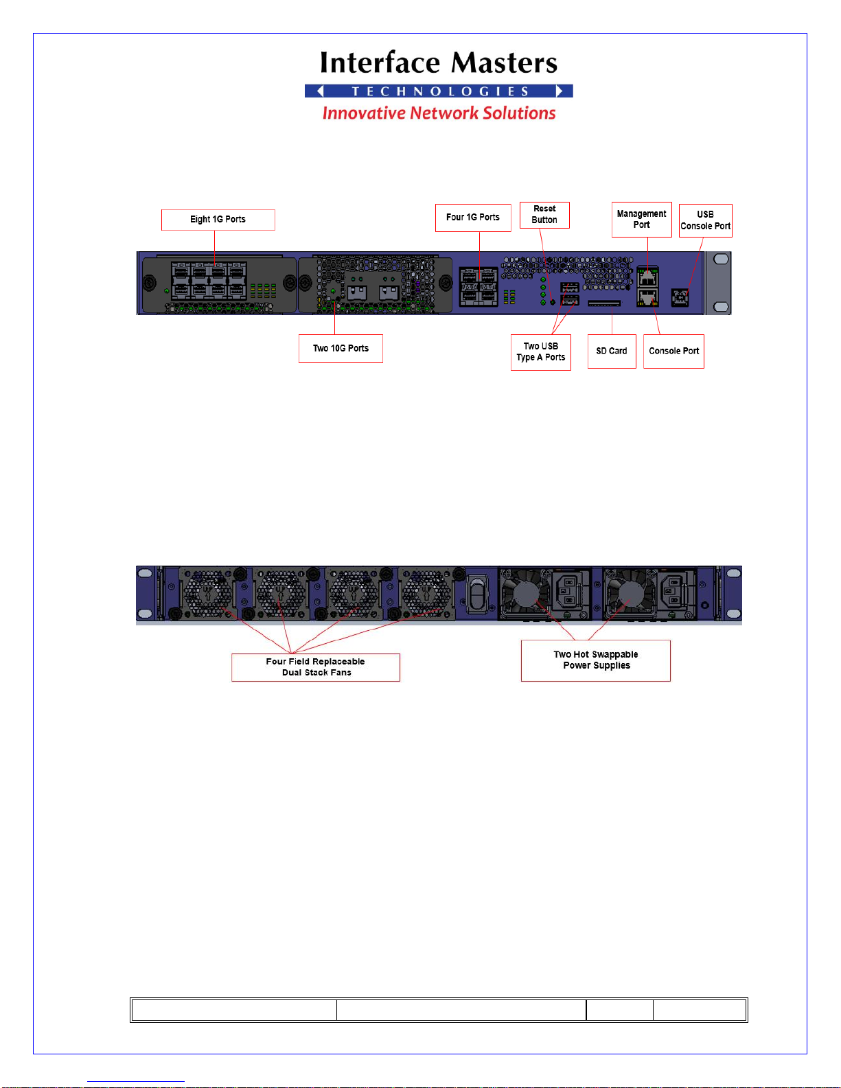
It provides the following external interfaces:
a) Four 1GE SFP ports.
b) One 10/100/1000 RJ45 management port
c) One RJ45 and one USB type B for system console
d) Two USB 3.0 type A Host ports
e) One SD card slot
f) Two hot swappable IO Modules
g) Four field replaceable dual stack fans
h) Two hot-swappable power supplies.
Page 6
TAHOE 8622 User Guide
REV: 01
07/27/2017
PAGE 6 OF 37
Internally, the system provides:
a) CPU with up to 32 cores operating at 1.4 GHz
b) Four DDR3 DIMM sockets
c) NOR flash (128Mb/16MB) for boot code storage
d) eMMC flash (8GB)
e) TPM module
f) RTC module
g) Temperature sensors
Page 7
TAHOE 8622 User Guide
REV: 01
07/27/2017
PAGE 7 OF 37
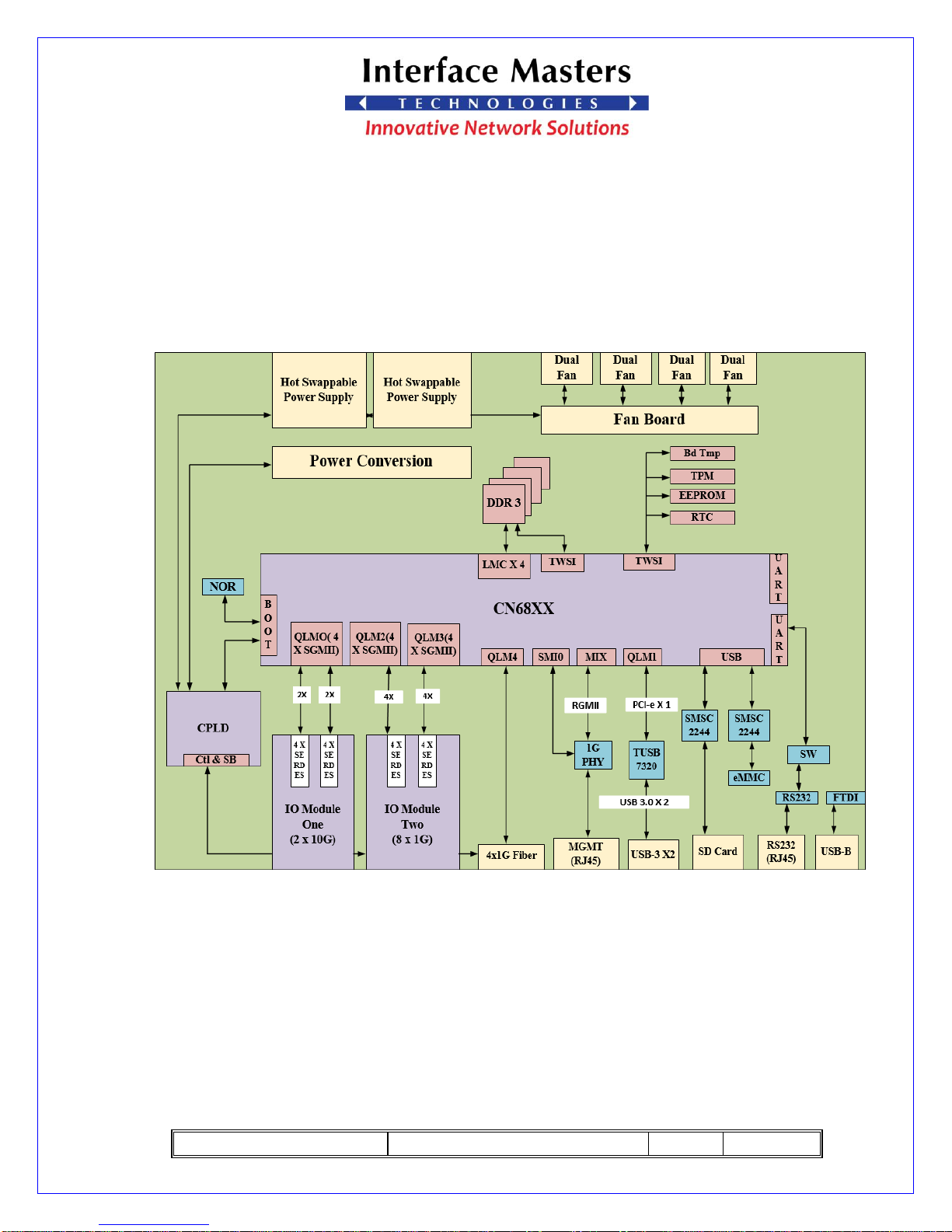
1.3 Functional Diagram
The below block diagram of TAHOE 8622 Board.
Figure 1, TAHOE 8622 Block Diagram
Page 8
TAHOE 8622 User Guide
REV: 01
07/27/2017
PAGE 8 OF 37
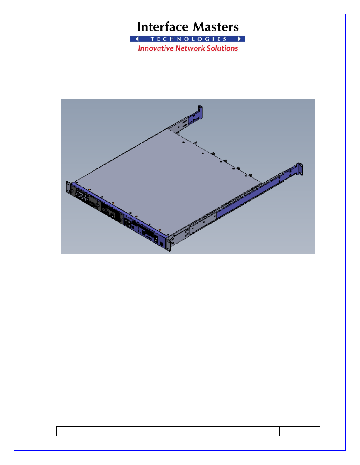
1.4 Physical Layout for System
Figure 2, 3D Image of TAHOE 8622 with Top View
Page 9
TAHOE 8622 User Guide
REV: 01
07/27/2017
PAGE 9 OF 37
Figure 3, 3D Image of TAHOE 8622 with Front View
Figure 4, 3D Image of TAHOE 8622 with Rear View
Page 10

TAHOE 8622 User Guide
REV: 01
07/27/2017
PAGE 10 OF 37
Figure 5, 3D Image for TAHOE 8622 with Cover OFF
Page 11
TAHOE 8622 User Guide
REV: 01
07/27/2017
PAGE 11 OF 37
2. CN68XX Processor
2.1 CN68XX Processor Overview
The Cavium OCTEON III CN68XX multi-core MIPS processor is the main processor
used in this system. The CN68XX has Four 72-bit DRAM controllers and support DDR3
SPD.
The following interfaces are provided by this part:
1. Boot bus
2. 4x SMI/MDIO bus
3. 2x I2C bus
4. 2x UART
5. 1x RGMII
6. SPI
7. 2x USB 2.0
8. Two USB 3.0
9. 4x 64b/72b DDR3 interface
Page 12
TAHOE 8622 User Guide
REV: 01
07/27/2017
PAGE 12 OF 37
2.2 DDR3 DRAM Controller
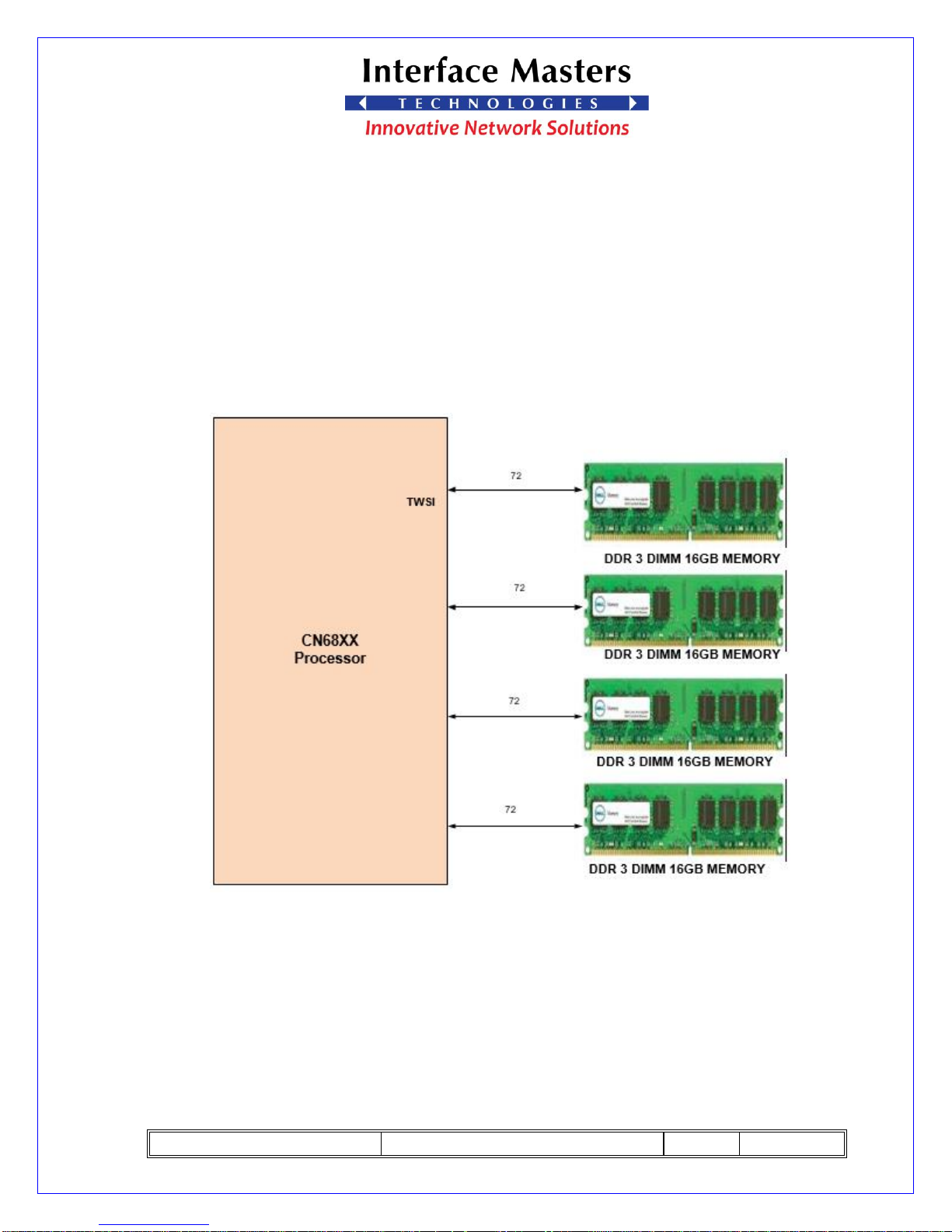
The CN68xx has four 72-bit DDR3 system memory controllers. The Tahoe 822
implements a single DDR3 DIMM slot per controller, for a total of four modules
maximum. Data rate is up to 1333 MT/s.
All controllers obtain equal amount if attached DRAM.
Figure 6, TAHOE 8622 DDR3 Controller Functional Diagram
Page 13
TAHOE 8622 User Guide
REV: 01
07/27/2017
PAGE 13 OF 37
2.3 eMMC/SD Interface
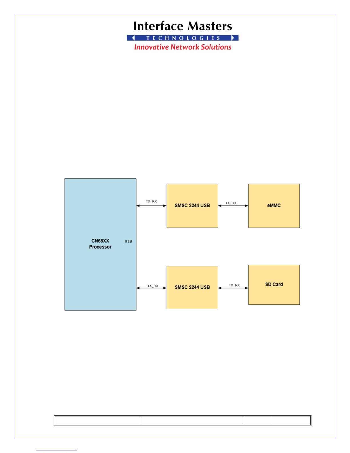
The CN68xx’s USB is connected to two SMSC2244 chip. an 8GB eMMC chip
device provides data storage.
a) The first SMSC2244 interface with eMMC.
b) The second SMSC224 connected to SD card.
Figure 7, TAHOE 8622 eMMC Functional Diagram
Page 14
TAHOE 8622 User Guide
REV: 01
07/27/2017
PAGE 14 OF 37
2.4 Boot Bus
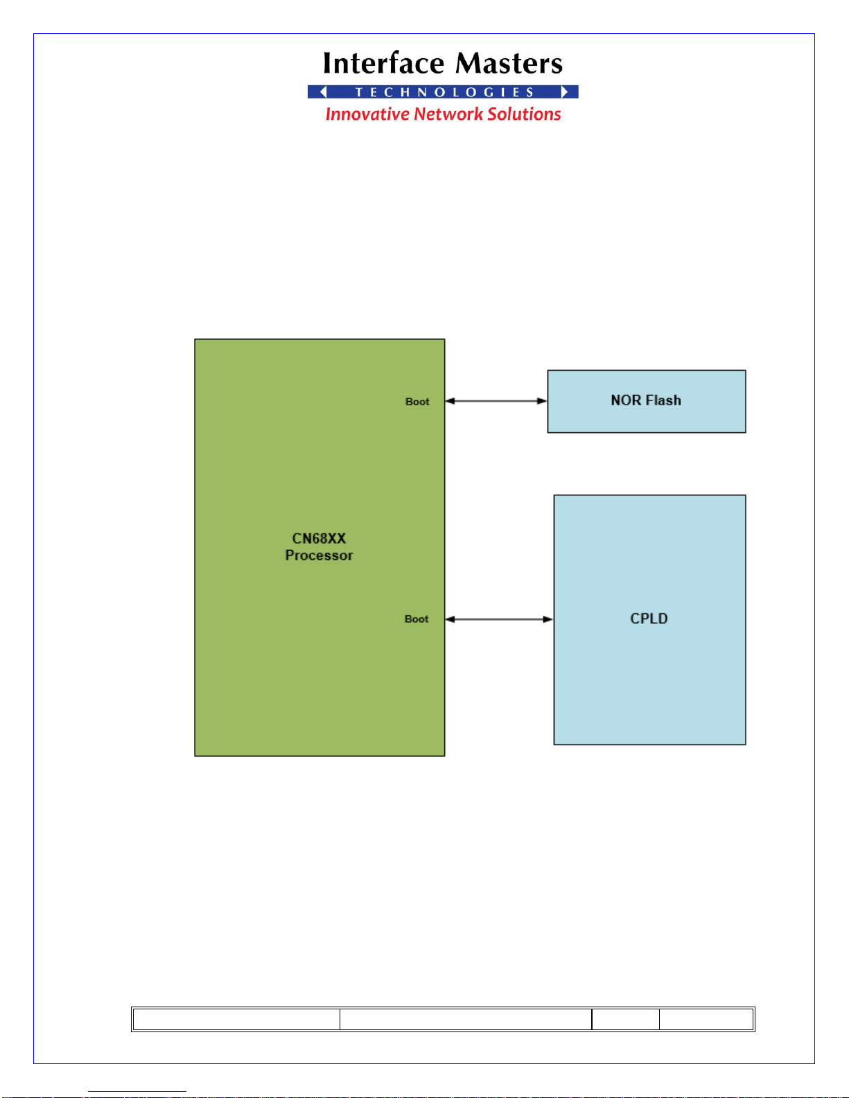
The CN68XX has general-purpose bus that typically attaches to nonvolatile
memory such as FLASH. It includes eight chip-selects, and 32 address/data lines.
The TAHOE 8622 boot bus interface connected to NOR flash memory and interface
with CPLD this bus will be the main communication path to the CPLD.
Figure 8, TAHOE 8622 Boot Bus Functional Diagram
Page 15
TAHOE 8622 User Guide
REV: 01
07/27/2017
PAGE 15 OF 37
2.5 On -board network interfaces
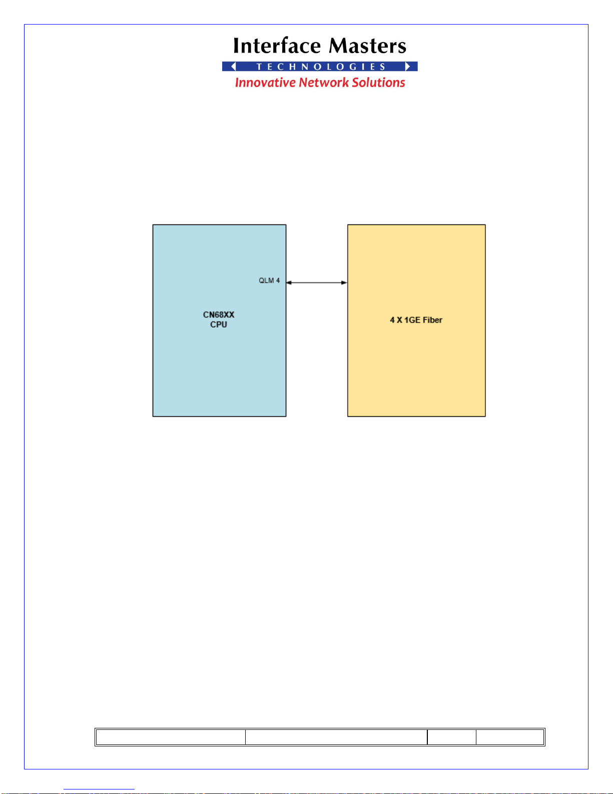
Four SGMII/SerDes channels from the processor are connected to a 1x4 SFP cage
which can support 1000bX or 10/100/1000bT SFPs.
Figure 9, Network Interface Functional Diagram
Page 16
TAHOE 8622 User Guide
REV: 01
07/27/2017
PAGE 16 OF 37
2.6 RGMII Management Port PHY
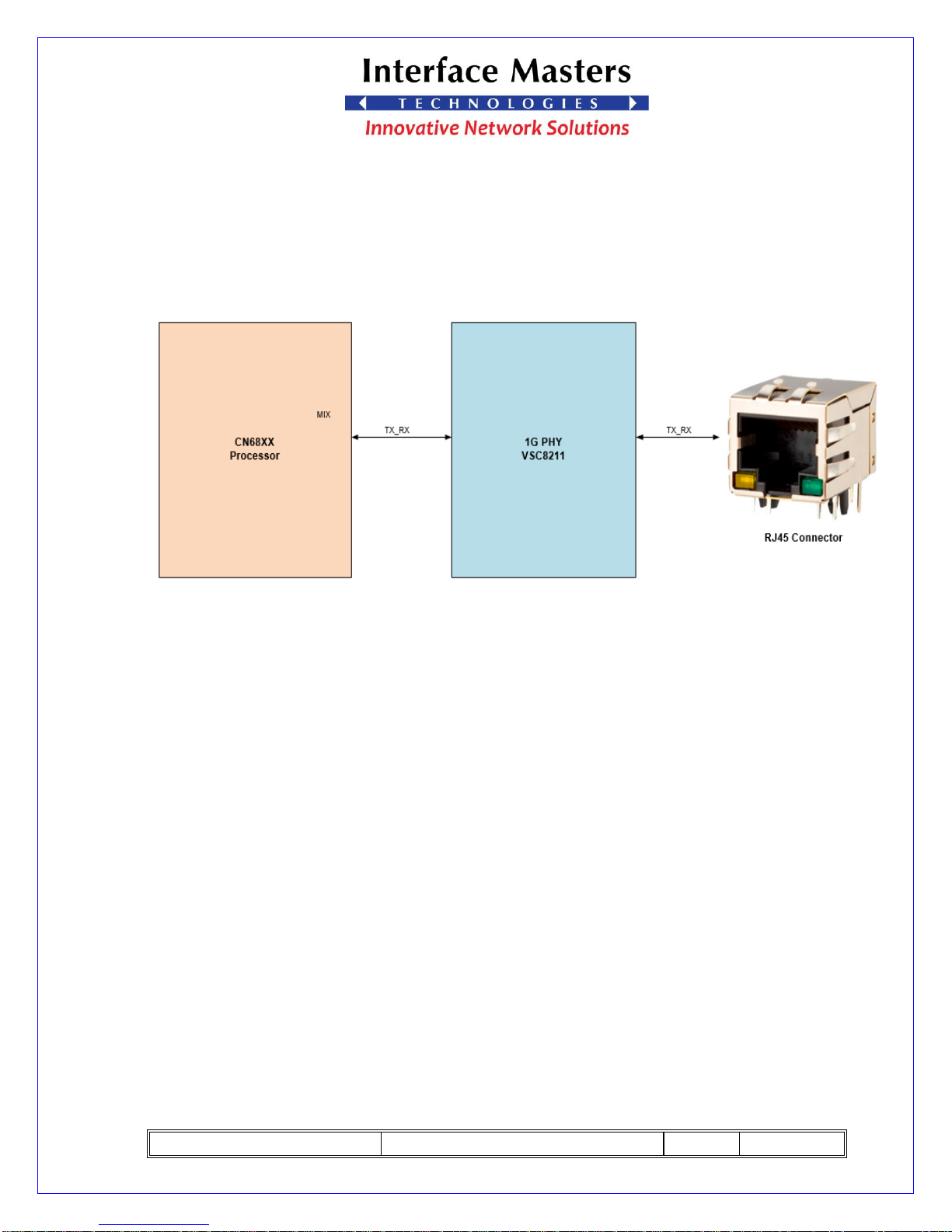
A Vitesse VSC8211 PHY provides management port through MIX and SIMO
connectivity to the front panel.
Figure 10, TAHOE 8622 RGMII Management Functional Diagram
Page 17
TAHOE 8622 User Guide
REV: 01
07/27/2017
PAGE 17 OF 37
2.7 UART Interface
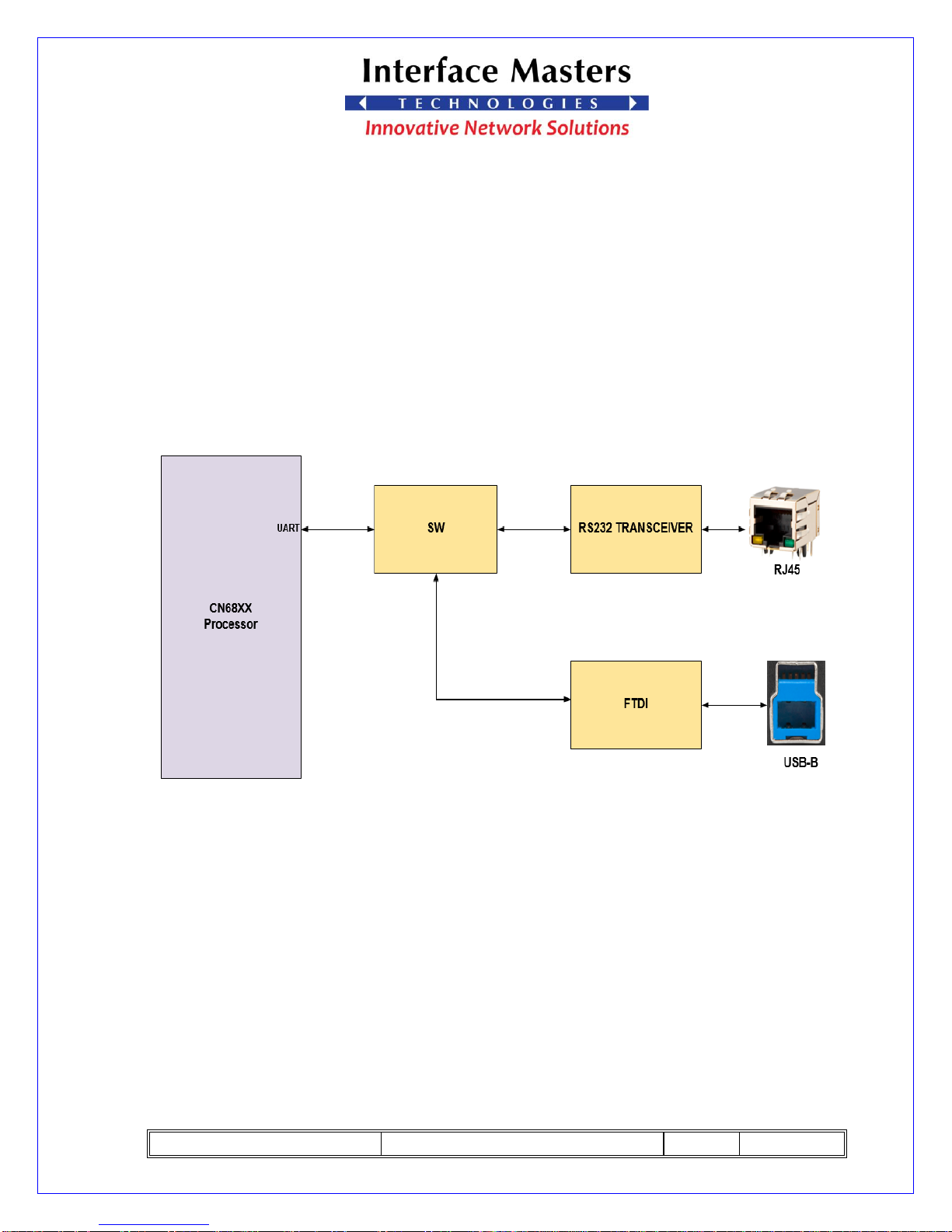
The CN68xx’s primary UART is connected to both a RS232 transceiver and an
RJ45 (for use with standard console cables) and a USB device port (type B - via a
USB-serial transceiver) on the front panel. Only one interface can be used at any
time.
The secondary UART is available for debug use.
Figure 11, TAHOE 8622 UART Functional Diagram
Page 18
TAHOE 8622 User Guide
REV: 01
07/27/2017
PAGE 18 OF 37
3. USB 3.0
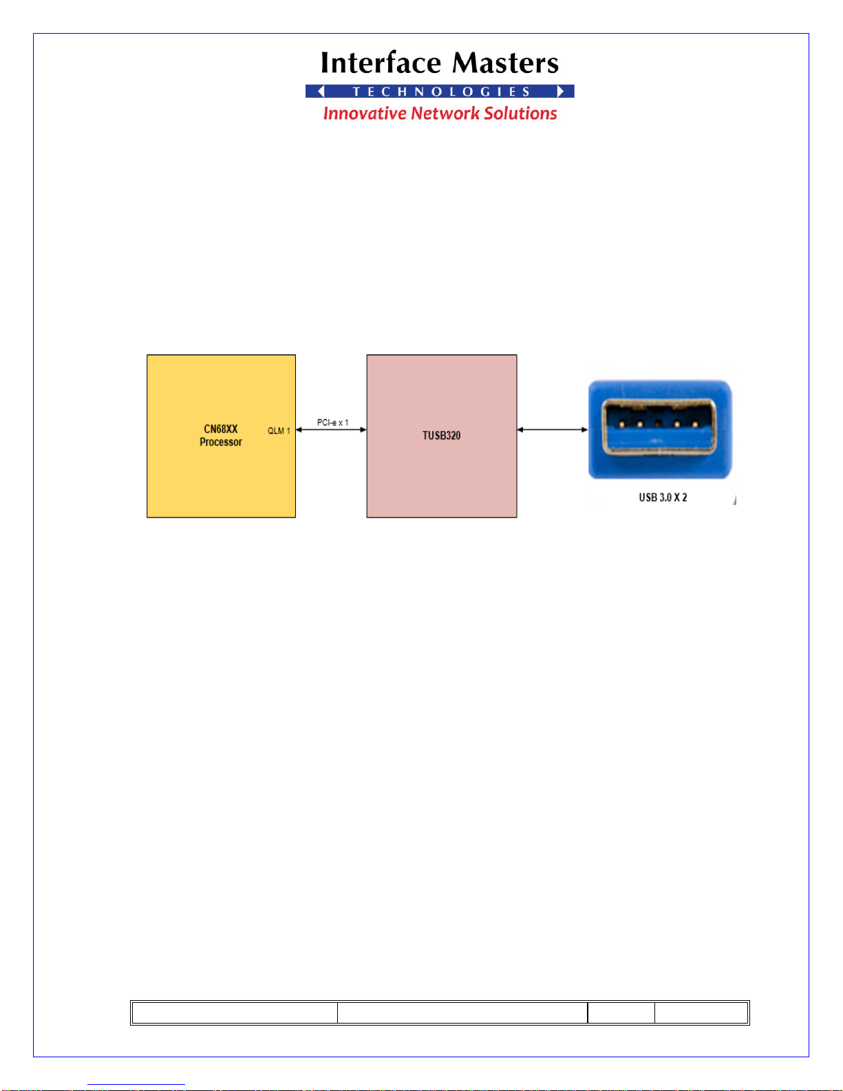
Two USB3.0 host ports (type A) on the front panel are connected to a TUSB7320
USB controller, connected to the CN68xx via a PCI-e lane.
Figure 12, TAHOE 8622 USB 3.0 Functional Diagram
Page 19
TAHOE 8622 User Guide
REV: 01
07/27/2017
PAGE 19 OF 37
4. USB 2.0
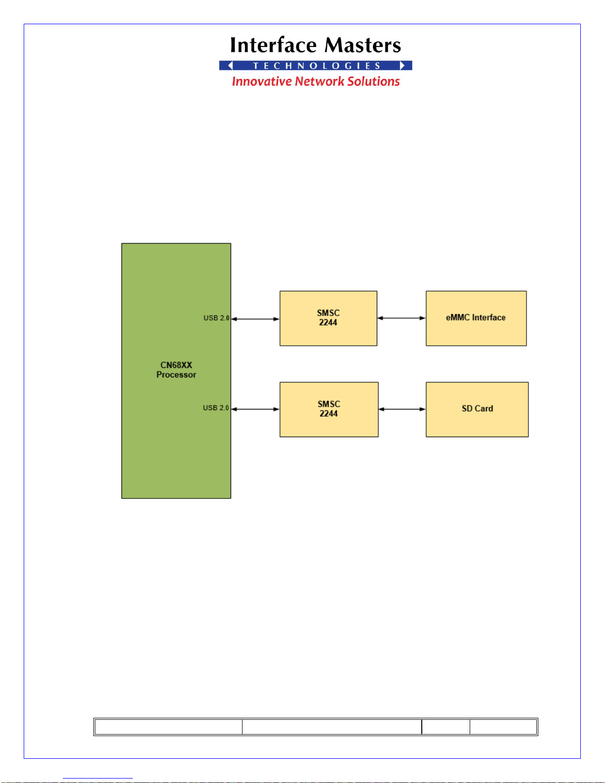
One USB 2.0 port from the CN68xx provides an SD card interface via the SMSC
USB2244i controller. The second USB 2.0 port provides eMMC storage, also via an
SMSC USB2244i.
Figure 13, TAHOE 8622 USB 2.0 Functional Diagram
Page 20
TAHOE 8622 User Guide
REV: 01
07/27/2017
PAGE 20 OF 37
5. Altera CPLD
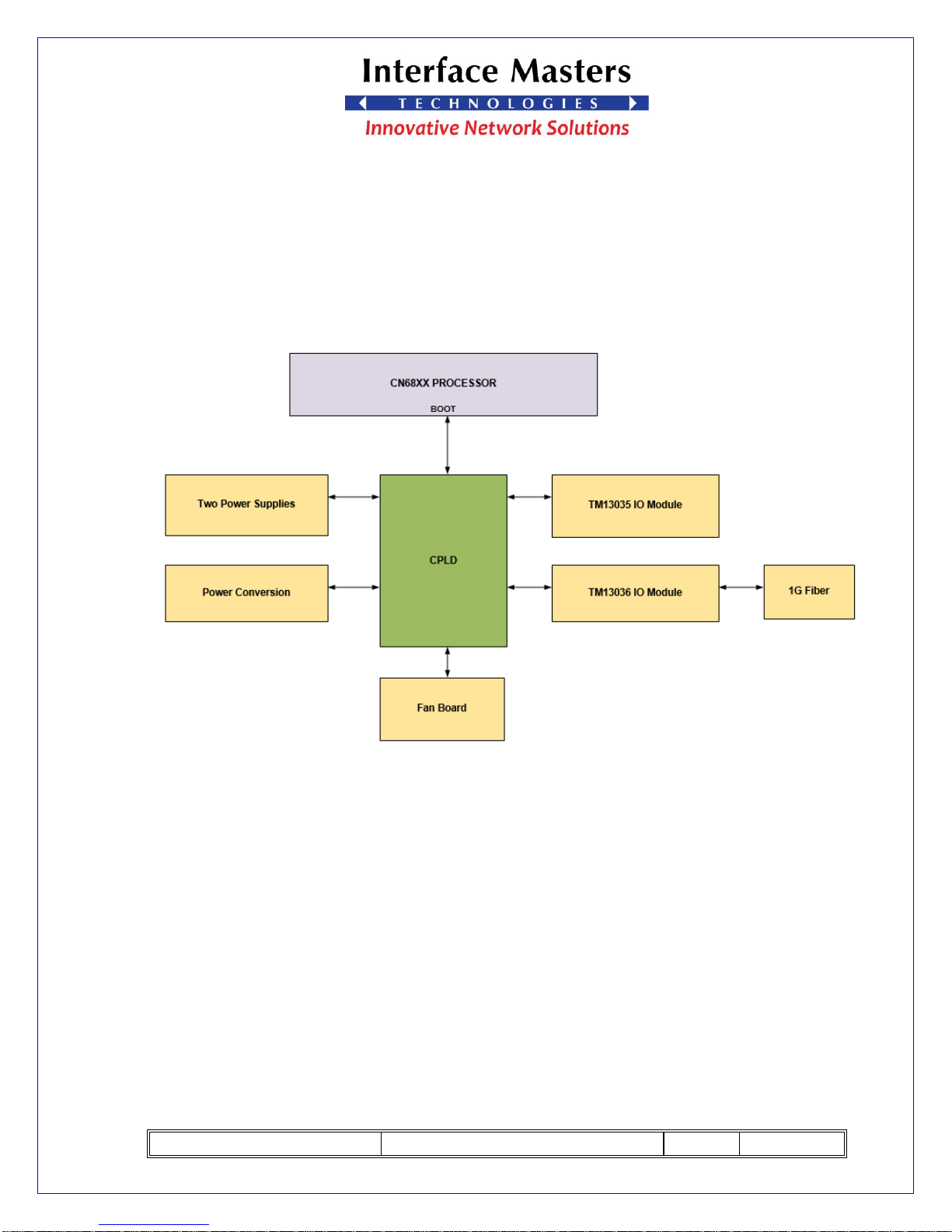
The TAHOE 8622 board uses an Altera MAX II CPLD to allow the main CPU to control the basic
functionality of the board.
Some of the features controlled by the CPLD are: Power Sequencing, I2C, FAN and LED control.
Figure 14, TAHOE 8622 CPLD Functional Diagram
5.1 Power Sequencing Control
CPLD enables over time the various voltage regulators to meet the voltage
Turn-On requirements for various IC. During this process, it checks the various PowerGood indication signals before enabling the next voltages in the sequence.
Page 21

TAHOE 8622 User Guide
REV: 01
07/27/2017
PAGE 21 OF 37
5.2 Access Interface
The CN68XX’s Boot Bus is the main interface to access the internal registers of the
CPLD and utilizes SPI interface.
5.3 I2C Interface
This module provides all the capabilities to allow the host to access the I2C Peripheral’s
internal registers through the Serial interface.
5.4 SPI Interface
This module provides all the capabilities to allow the host to access the SPI Peripheral’s
internal registers through the Serial interface.
5.5 Drive LED data stream
CPLD decodes the LED data stream from each PHY and use it to drive the LEDs on the
data ports.
Page 22
TAHOE 8622 User Guide
REV: 01
07/27/2017
PAGE 22 OF 37
6. Console Port
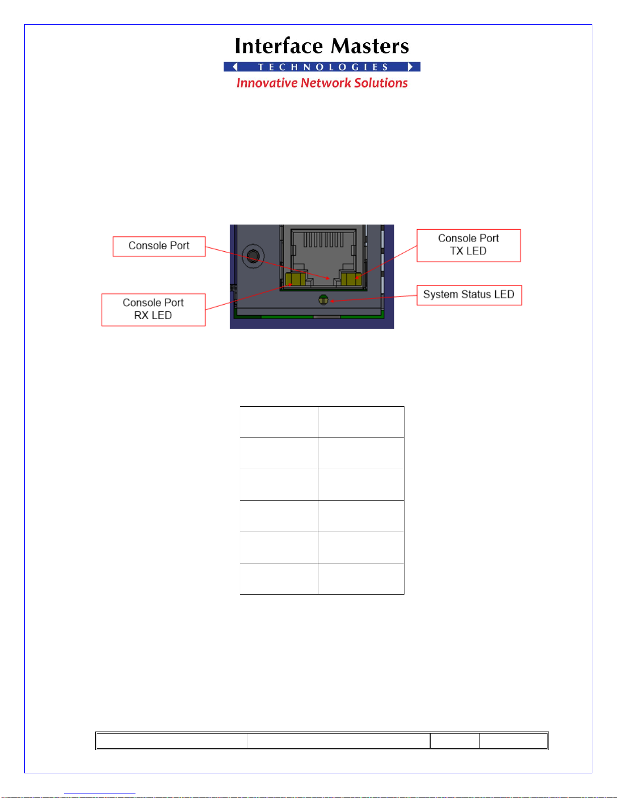
The console port is connected to UART interface of the control CPU board through an
RS232 level translator.
Figure 15, Console Port
The setting is as shown below:
Setting
Parameter
Baud Rate
115200
Data Bits
8
Parity
None
Stop Bit
1
Flow Control
None
Table 1, Console Port Setting
Console Port RX LED: Blinking Green indicates receiving.
Console Port TX LED: Blinking Green indicates transmitting.
Page 23
TAHOE 8622 User Guide
REV: 01
07/27/2017
PAGE 23 OF 37
7. LED Control
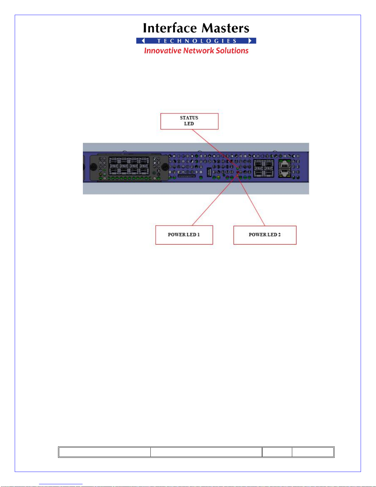
The CPLD drive the system LED based on system status.
Figure 16, LED Control
7.1 Power LED 0
❖ Off indicates “Left Power Supply is off”.
❖ Solid Green indicates “Left Power supply is Good”.
7.2 Power LED 1
❖ Off indicates “Right Power supply is off”.
❖ Solid Green indicates “Right Power Supply is Good”.
7.3 Status LED
❖ Solid Green indicates “System OK”.
❖ Blinking Green indicates “System initializing”.
Page 24
TAHOE 8622 User Guide
REV: 01
07/27/2017
PAGE 24 OF 37
8. Boot Devices
Tahoe 8622 supports three boot devices
8.1 SPI NOR Flash
SPI NOR Flash is 16GB it is the default boot device.
8.2 SD card
SD card supports capacity up to 128GB.
8.3 eMMC
eMMC is 4GB device and it is the second boot device after the SPI NOR flash.
Page 25
TAHOE 8622 User Guide
REV: 01
07/27/2017
PAGE 25 OF 37
8.4 Selecting Boot Device
Registered BOOT_CSR in the CPLD Selects Boot Device
The boot device could be selected by writing the appropriate values into BDSL_2 and
BDSL_3
BOOT_CSR – Boot Control and Status
7
6 5 4 3 2
1
0
CN_FAILSF
res
res
res
BDSL_3
BDSL_2
res
res
Table 2, Boot Device Register
bit 7 CN_FAILSF – CPU Failsafe
Upon reset, it is set to 1, but if the CPU fails to boot it is set to 0.
bits 6:4 Reserved
bits 3:2 BDSL [3:2] – Boot Device Select
Upon power up, SPI NOR is selected as default device.
The software can change these bits and cause a re-boot by writing a 1 into
the RE_BOOT bit.
These bits are not changed by a hardware reset.
BDSL_ [3:2]
Boot Device
11
eMMC
10
SPI Flash
01
reserved
00
SD Card
Table 3, Boot Device Bits
Page 26
TAHOE 8622 User Guide
REV: 01
07/27/2017
PAGE 26 OF 37
9. I/O Modules
TAHOE 8622 supports two hot-swappable I/O modules bays. though a unit may
only be swapped out for an identical model without rebooting the system.
Interface Masters Technologies develops various I/O modules based on customer
request. At the time of this writing there are two models of I/O modules.
a) TM13036 I/O module, it supports two ports of 1/10GE.
b) TM13035 I/O module, supports eight ports of 1GE
Page 27
TAHOE 8622 User Guide
REV: 01
07/27/2017
PAGE 27 OF 37
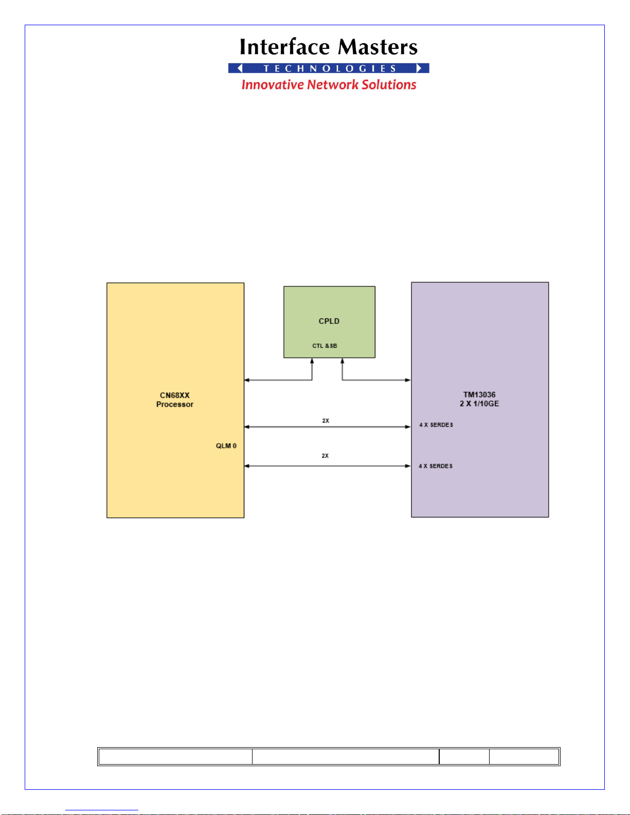
9.1 I/O Module TM13036
This I/O module, supports two ports of 1/10GE.
I/O module interfaces with CN68XX with four serdes interface through the
QLM0 lanes and connects with CPLD control functions. CPLD connected to
the main board CPLD via serial bus to support control and serial
communications.
Figure 17, TAHOE 8622 TM13036 I/O Module Functional Diagram
Page 28
TAHOE 8622 User Guide
REV: 01
07/27/2017
PAGE 28 OF 37
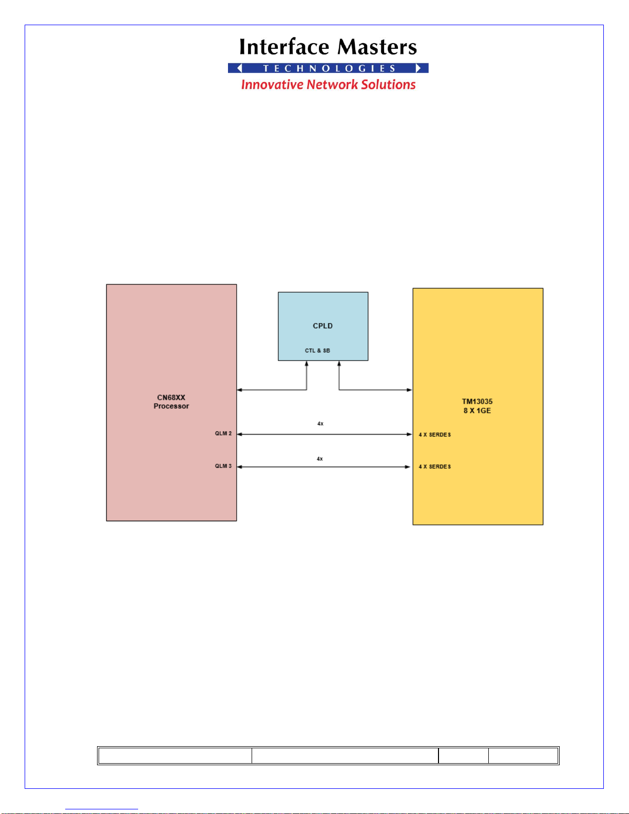
9.2 I/O Module TM13035
TM13035 I/O module supports eight ports of 1GE.
TM13035 I/O module interfaces with CN68XX with four SERDES interface
through the QLM 2 and QLM 3 lanes and connects with CPLD control functions. CPLD
connected to the main board CPLD via serial bus to support control and serial
communications.
Figure 18, TAHOE 8622 TM13035 I/O Module Functional Diagram
Page 29
TAHOE 8622 User Guide
REV: 01
07/27/2017
PAGE 29 OF 37
10. POWER
The TAHOE 8622 provide two redundant hot-swappable 780Watt power supplies
with 12V output. It provides hot-swap and fail over capability.
Input Voltage
(VAC)
Max Input Current
(A)
100
10
240
4
Table 4,Input Power
Output Voltage
(DC)
Max Output Current
(A)
12
65
Table 5, Output Power
10.1 Power Consumption
The TAHOE 8622 consume 150W. power depending on CPU speed, DRAM size,
DRAM speed, Number of active I/O ports.
Page 30
TAHOE 8622 User Guide
REV: 01
07/27/2017
PAGE 30 OF 37
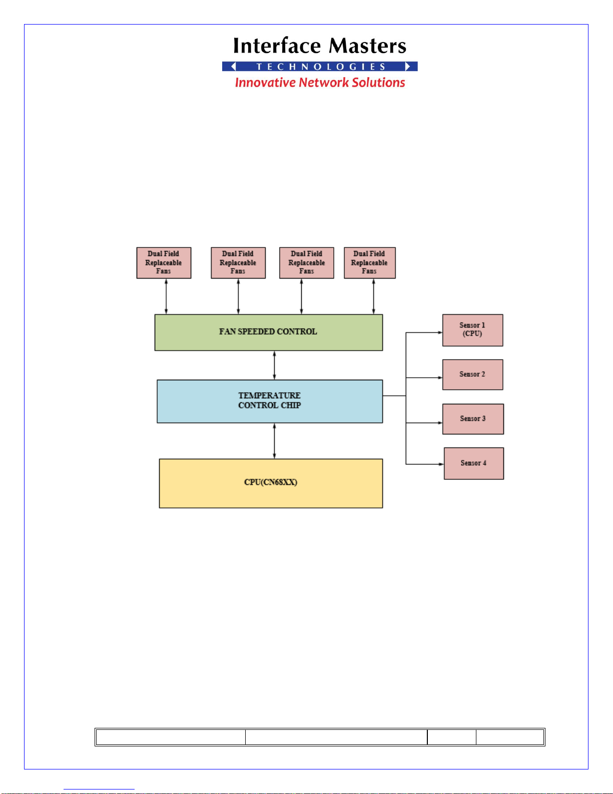
10.2 Cooling Fan
TAHOE 8622 provide four dual replaceable fans with speeded control and
temperature control chip with four sensors. The cooling fans the system depends on
temperature of the system and it is automatically adjusted when it is required.
Figure 19, Cooling Fan of TAHOE 8622
Page 31
TAHOE 8622 User Guide
REV: 01
07/27/2017
PAGE 31 OF 37
11. Enclosure
11.1 Physical Dimensions
Inches
MM
Height
17
445
Width
1.73
44
Length
17.25
438
Table 6, Physical Dimensions
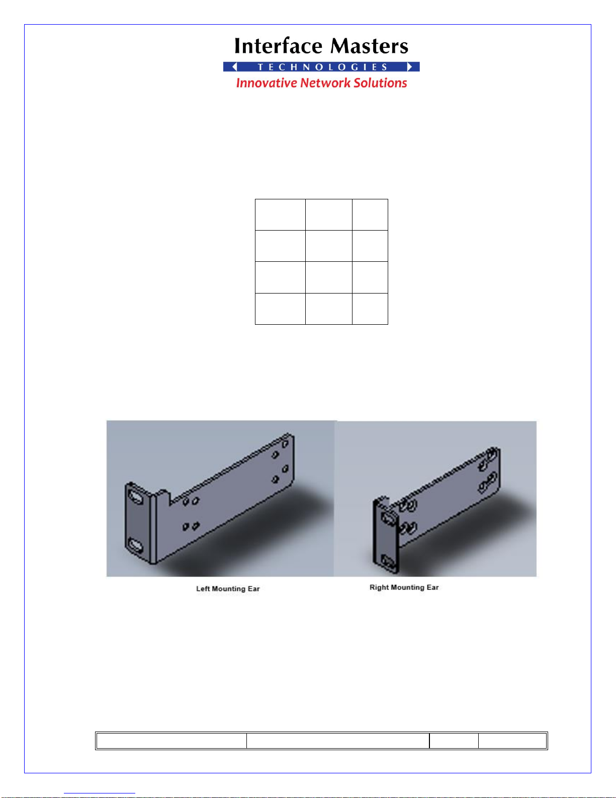
11.2 Mounting Ears
TAHOE 8622 comes standard with two ears for mounting to 19-inch rack.
Figure 20, TAHOE 8622 Mounting Ears
Page 32
TAHOE 8622 User Guide
REV: 01
07/27/2017
PAGE 32 OF 37
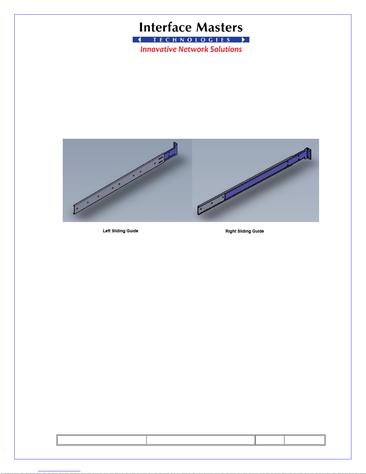
11.3 Sliding Guides
TAHOE 8622 comes standard with two sliding guides for 19-inch rack.
Figure 21, TAHOE 8622 Sliding Guides
Page 33
TAHOE 8622 User Guide
REV: 01
07/27/2017
PAGE 33 OF 37
12. Customer Support
12.1 Technical Assistance
Interface Masters Technologies technical support staff is available to assist you with
questions that you may have. Please contact Interface Masters Technologies using one of
the methods shown below.
Phone: (408) 441-9341 ext. 100
Fax: (815) 364-0888
Email: [email protected]
Website: http://www.interfacemasters.com
12.2 Life Support Policy
Interface Masters Technologies products are not authorized for use as critical
components in life support devices or systems without the express written approval of the
CEO of Interface Masters Technologies. Refer to the following for definitions of critical
components and life support devices.
A critical component is any component of a life support device or system whose
failure to perform can be expected to cause the failure of the life support device or system,
affect its safety, or limit its effectiveness.
Life support devices or systems are devices or systems which support or sustain life,
and whose failure to perform, when properly used in accordance with instructions for use
provided in the labeling, can be reasonably expected to result in a significant injury to the
user.
Page 34
TAHOE 8622 User Guide
REV: 01
07/27/2017
PAGE 34 OF 37
12.3 Warranty
Standard hardware warranty period is ONE year from date of purchase. Interface
Masters Technologies will, solely at its option, repair or replace products, which prove to
be defective in materials or workmanship, provided they are returned to an Interface
Masters Technologies authorized repair center. Shipment to Interface Masters Technologies
is at the customer's expense. Interface Master Technologies pays return shipment by ground
Products, which in Interface Masters Technologies opinion, have been subject to misuse,
abuse, neglect or unauthorized alteration or repair are excluded from this warranty.
Page 35
TAHOE 8622 User Guide
REV: 01
07/27/2017
PAGE 35 OF 37
13. Ordering Part Numbers
13.1 System Ordering Part Numbers
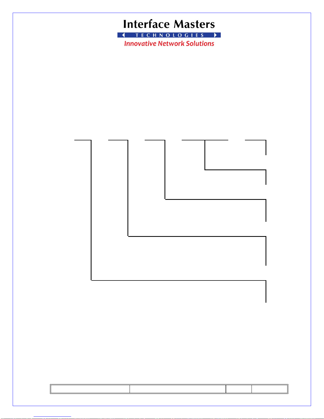
TAHOE
8622
CPU
CPU
DRAM
1st IO
2nd IO
Power
Speed
Size
Module
Module
Supply
(MHZ)
(GB)
Type
1=AC
2=DC
1=TM13035
2=TM13036
1=16
2=32
3=64
1=800
2=1000
3=1200
4=1400
1=CN6860
2=CN6870
3=CN6880
Table 7, Ordering Part Numbers
Page 36
TAHOE 8622 User Guide
REV: 01
07/27/2017
PAGE 36 OF 37
13.2 Standard Configurations
Following Configuration will be stocked with Four weeks of lead time
Ordering Number
Configuration
TAHOE 8622-332221
TAHOE 8622-
CPU CN6880
CPU Speed 1200MHZ
32GB DRAM
Two TM13036 IO Modules
AC power supply
TAHOE 8622-332111
TAHOE 8622-
CPU CN6880
CPU Speed 1200MHZ
32GB DRAM
Two TM13035 IO Modules
AC power supply
Table 8, Standard Configurations
Page 37
TAHOE 8622 User Guide
REV: 01
07/27/2017
PAGE 37 OF 37
13.3 Module Part Numbers
Module Part Number
Description
TM13035
Support Eight ports of 1GE
TM13036
Support Two ports of 1/10GE.
Table 9, Module Part Numbers
13.4 Accessories Part Numbers
Part Number
Description
IM3389
Left & Right mounting ears
IM3388
Sliding Guides
Table 10, Accessories Part Numbers
9.3 Transceivers
Ordering
Part Number
Manufacturer
Description
163-0007679
Finisar
1/10Gb SFP+ SR / multi-mode 850 nm optics
163-0007184
Finisar
1/10Gb SFP+ LR / single mode 1310 nm optics
164-0007148
Finisar
10/100/1000 BASE-T copper
Table 11, Transceivers part Numbers
 Loading...