

Page 1
USER’S MANUAL
MCA-E4852A
PPrroodduucctt MMooddeell:: CCBBII--44885522A
A
Ver. 1.1
www.interface.co.jp
Page 2
Notes to Users
The specifications of the product are under continuous improvement and while every effort is made to keep this
manual up-to-date, we reserve the right to update the contents of this user’s manual without prior notice. Therefore,
you should thoroughly read this user’s manual even if you have often purchased this product before.
Using this product requires technical knowledge of hardware and software.
Use this product only under the specified conditions such as power supply, voltage, temperature, and humidity range.
Interface Corporation’s products are not designed with components intended to ensure a level of reliability suitable for
use under conditions that might cause serious injury or death.
Please consult our Technical Support Center if you intend to use our products for special purpose, such as use for
moving vehicles, medical treatment, aerospace engineering, controlling nuclear power, submerged translators and so
on. This product is made under strict quality management, however, when using this product for the purposes that
may result in any damages, lost profits, or any other incidental or consequential damages resulting from breakdown of
this product, the user is required to take adequate and appropriate measures, such as installing safety devices to avoid
possible serious accidents.
Conventions Used in This Manual
This icon denotes a warning, which advises you of precautions to take to avoid
injury, data loss, or system crash.
This icon denotes a note, caution, or warning.
Indemnification
Interface Corporation makes no warranties regarding damages resulting from installation or use of this product,
whether hardware or software, and assume that such risk reverts to the user.
Interface Corporation shall not be liable for any incidental or consequential damages, including damages or other
costs resulting from defects which might be contained in the product, product supply delay or product failure, even
if advised of the possibility thereof. Customer’s right to recover damages caused by fault or negligence on the part
of Interface Corporation shall be limited to the amount paid by the customer for that product.
This product including its software may be used only in Japan. Interface Corporation can not be responsible for the
use of this product outside Japan. Interface Corporation does not provide technical support service outside Japan.
Warranty
Interface Corporation products are warranted for a period of either one year or two years from the date of shipment, as
evidenced by receipts or other documentation. This warranty does not apply to the software products and expendable
supplies such as batteries.
Note: You can determine the warranty period at our Web site by the serial number of your product. Those without
Internet access should contact the Sales Information Center.
During the warranty period Interface Corporation will, as a general rule, replace or recondition the defective product
without charge, in which case the user will be required to pay the shipping costs, except as set forth below.
The Warranty provided herein does not cover expendable supplies such as batteries and damages, defects,
malfunctions, or failures caused by impact during transportation while under owner’s responsibility; owner’s failure to
follow the instructions and the precautions contained in this manual; modification and/or repair of the product by other
than Interface Corporation, trouble caused by use with peripherals not specified by Interface Corporation, power
failure or surges, fire, earthquake, tidal wave and/or flood.
This warranty applies only when the product is used in Japan.
Interface Corporation warrants its repairs for six months, and will again repair the same defective part without
additional charge provide the product is economically repairable. In that case, the user should attach a copy of the
most recent repair report to the repair request form. If no repair report is attached, it will be considered as a new repair
request.
Before You Export Interface Products
The foreign exchange and foreign trade law of Japan controls the export of this product, due to its possible use as a STRATEGIC
MATERIAL. Therefore, before you export this product, you must secure an export permit from the Ministry of Economy, Trade and
Industry of Japan.
Page 3
MCA-E4852A Ver. 1.1
Revision History
Version Date Comments
1.0 January 2004 User’s manual MCA-E4852A published.
1.1 July 2004 Manual revised:
3.1 Hardware Specifications
Maximum bit rate changed as follows:
1 Mbps → 60 kbps to 1 Mbps
Section 5.4 Multiple CardBus Cards added.
Chapter 6 Glossary added.
Due to constant product improvements, the information in this user’s manual is subject to change without prior
notice.
-1- Interface Corporation
Page 4

MCA-E4852A Ver. 1.1
-Contents-
Chapter 1 Introduction...............................................................................3
1.1 Summary...............................................................................................................................3
1.1.1 Features................................................................................................................. 3
1.2 Optional Products .................................................................................................................4
1.2.1 Accessories............................................................................................................ 4
Chapter 2 Signal Definitions...................................................................... 5
2.1 Cable Connector Pin Assignments .......................................................................................5
2.2 Signals ..................................................................................................................................5
Chapter 3 Specifications ...........................................................................6
3.1 Hardware Specifications ....................................................................................................... 6
3.2 Electric Characteristics .........................................................................................................7
3.3 Circuit Diagram .....................................................................................................................8
3.4 External Input/Output Circuit................................................................................................. 8
3.5 CAN Controller Access ......................................................................................................... 9
3.5.1 Basic Mode ............................................................................................................9
3.5.2 FIFO Mode............................................................................................................. 9
Chapter 4 External Connections .............................................................10
4.1 Example Connection........................................................................................................... 10
Chapter 5 Installation .............................................................................. 11
5.1 Card Installation.................................................................................................................. 11
5.2 Driver Software Installation .................................................................................................11
5.3 Card Uninstallation.............................................................................................................. 11
5.4 Multiple CardBus Cards ......................................................................................................12
Chapter 6 Glossary .................................................................................13
6.1 List of Definitions................................................................................................................. 13
Chapter 7 Notes for Users ......................................................................14
7.1 Caution, Periodic Inspections, and Storage ........................................................................ 14
Chapter 8 Troubleshooting...................................................................... 16
8.1 Checkpoints ........................................................................................................................16
Interface Corporation -2-
Page 5
MCA-E4852A Ver. 1.1
Chapter 1 Introduction
1.1 Summary
The CBI-4852A is a CAN (Controller Area Network) Interface board for CardBus-based computers. Two
high-speed communications channels compliant with ISO11898-2 are achieved with the SJA1000 CAN
controller (Royal Philips Electronics or equivalent) and the PCA82C250 CAN transceiver (Royal Philips
Electronics or equivalent). The maximum bit rate is 1 Mbps. Each channel provides independent
communications at individually set bit rates. With the large-capacity FIFO buffer, this board can
transmit/receive messages at high speed. A simple operation checks of CAN bus can be performed. By using
the JKC-4851A, the termination resistors can be connected.
Packing List
Item Part Number Qty.
CardBus Card
Cable
1.1.1 Features
1. CAN protocol
The CBI-4852A can perform high-speed CAN communications compliant with the CAN 2.0B protocol
and ISO11898-2. This product uses the SJA1000 CAN controller (Royal Philips Electronics or equivalent)
and the PCA82C250 CAN transceiver (Royal Philips Electronics or equivalent). The maximum bit rate is
1 Mbps.
CBI-4852A
JKC-4851A
1
1
2. One CAN controller for each channel
The CBI-4852A incorporates one CAN controller per channel. Each channel provides independent
communications at individually set bit rates. The system clock frequency is 24 MHz.
3. High-performance CAN controller
By adopting the SJA1000 CAN controller, the following functions are provided:
error count, error code capture, two receiver message filters, etc.
4. Large-capacity FIFO buffer
The CBI-4852A incorporates 64 messages for transmit FIFO and 64 messages for receive FIFO per
channel. This feature reduces CPU load. It also allows you to transmit/receive messages at high speed
without data loss.
5. Pseudo message
Pseudo messages can be transmitted. By using this function, a specified pseudo message can be transmitted
in a fixed cycle. Simple operation checks of CAN bus can be performed.
6. CAN bus monitor
The CBI-4852A can monitor messages and error status which were transmitted to the CAN bus. It can also
confirm those timings to monitor by 10 µs. Moreover, it can configure response messages not to output.
This feauture helps you to monitor without loading to network.
-3- Interface Corporation
Page 6
MCA-E4852A Ver. 1.1
1.2 Optional Products
1.2.1 Accessories
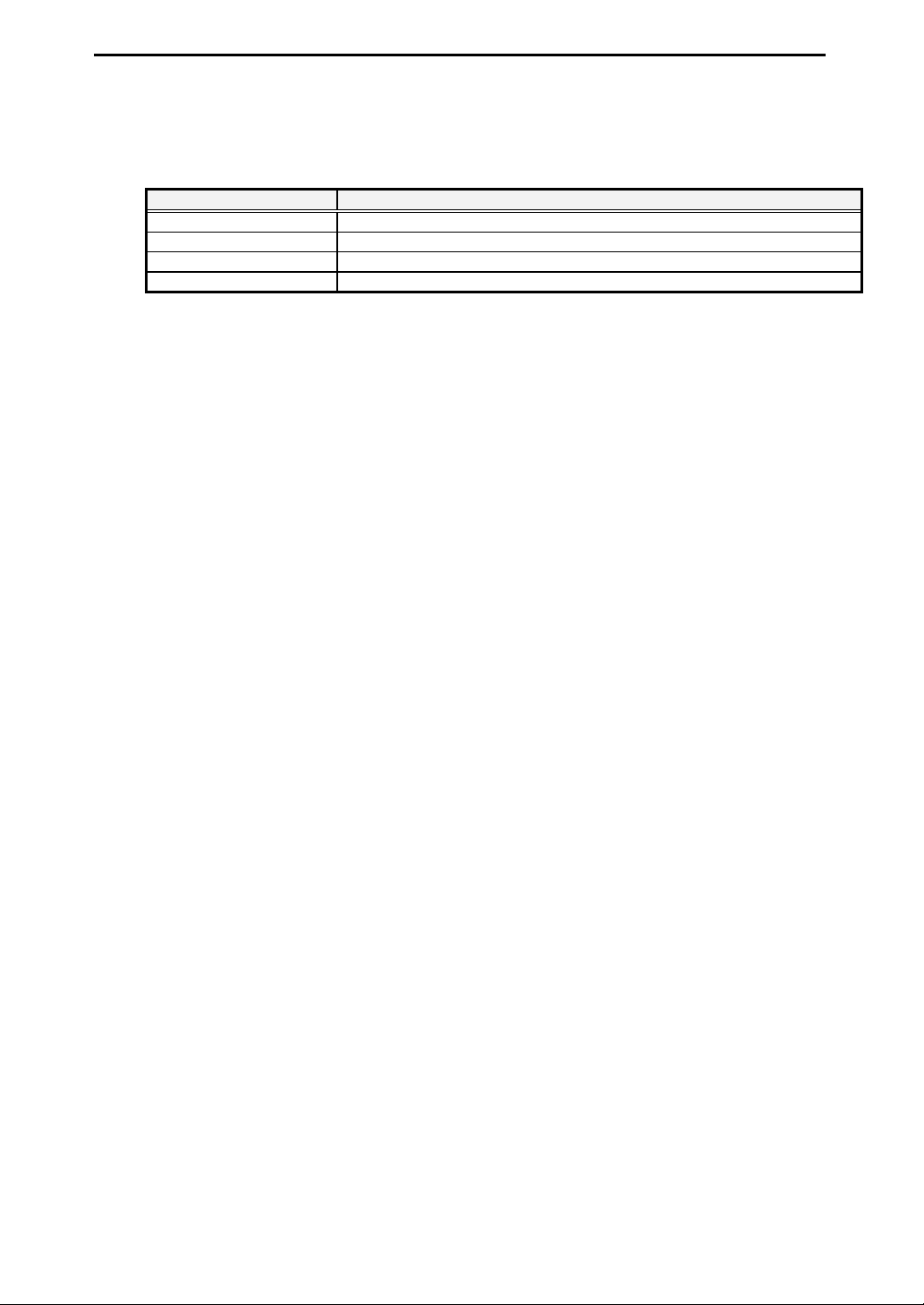
Part Number Description
GPC-4851 (Japanese) Driver software for Windows XP/2000/Me/98
GPF-4851 (English) Driver software for Windows XP/2000/Me/98
GPG-4851 (Japanese) Driver software for Linux, RTLinux, SH-Linux, and SH-RTLinux
GPH-4851 (English) Driver software for Linux, RTLinux, SH-Linux, and SH-RTLinux
Refer to our Web site for the latest information and prices of optional products.
Note: You may download software drivers from our Web site free of charge. We also provide software drivers
on CD-ROM for a nominal fee.
Interface Corporation -4-
Page 7
Chapter 2 Signal Definitions
NCN
N
NCN
N
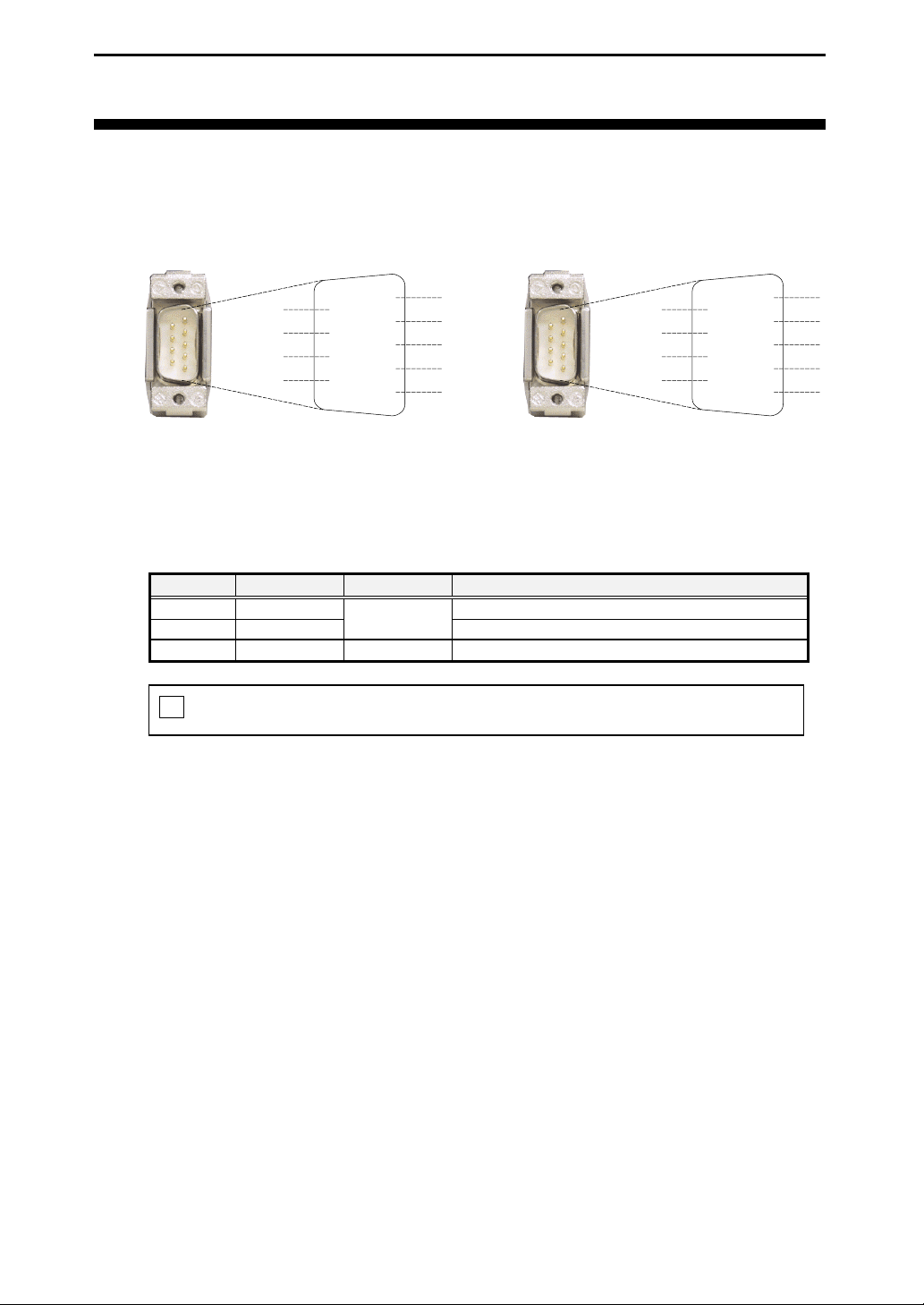
2.1 Cable Connector Pin Assignments
• CN1, CN2
MCA-E4852A Ver. 1.1
<CN1>
2.2 Signals
Signal Description
Signal
CANL
CANH
GND
! Connect the cable only with the CBI-4852A.
NC
CANH1
NC
NC
Pin Number Direction
6
7
8
9
Connector catalog number : 17JE-23090-02 (DC2C)
2
7
3
Input/Output
1
2
3
4
5
NC: Not connected
C
CANL1
GND
C
CAN Low
CAN High
Ground
<CN2>
NC
CANH2
NC
NC
Description
1
6
2
7
3
8
4
9
5
C
CANL2
GND
C
-5- Interface Corporation
Page 8
MCA-E4852A Ver. 1.1
Chapter 3 Specifications
3.1 Hardware Specifications
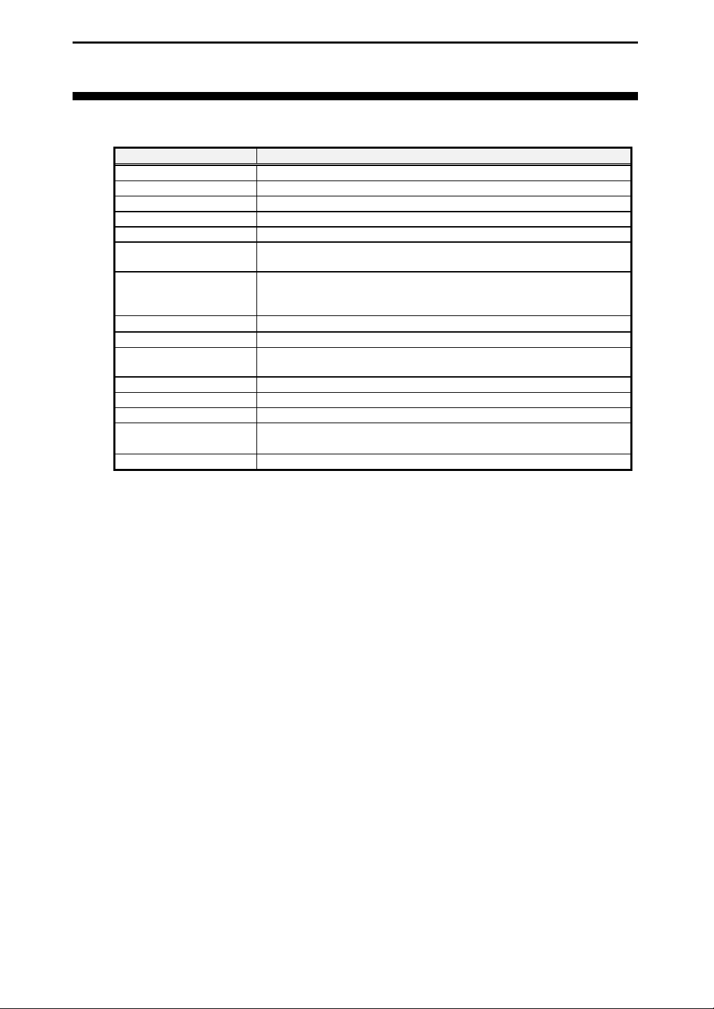
Parameter Specification
Number of channels 2
Communications standards CAN2.0B protocol-based, ISO11898-2
Maximum bit rate High-speed CAN: 60 kbps to 1 Mbps
CAN controller SJA1000 (Royal Philips Electronics) or equivalent
CAN transceiver PCA82C250 (Royal Philips Electronics) or equivalent
CAN controller system
clock frequency
Transmit/receive buffer
memory
Memory size
Maximum cable length 40 m
Number of connection
units
Power consumption +3.3 Vdc (+/-5%): 300 mA (typ.)
Bus requirements PC Card Standards-Based CardBus
Card size PCMCIA/JEITA Type II
Environmental conditions
I/O connector CH1, CH2: 9-pin D-sub male connector (attached cable connection)
24 MHz
64 messages for transmit each channel
64 messages for receive each channel
64 records for error status each channel
4 kB × 2
30 (max.)
Operating temperature: 0 °C to 50 °C
Relative humidity: 20% to 90% (non-condensing)
Interface Corporation -6-
Page 9
3.2 Electric Characteristics
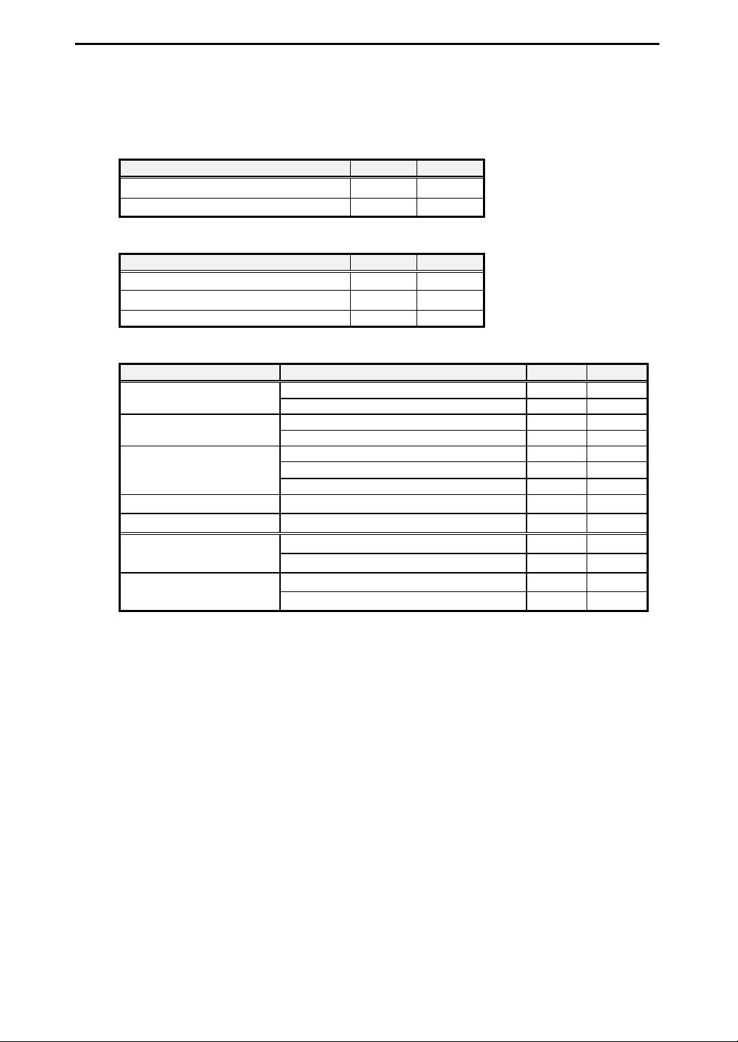
The lists below show the electric characteristics of the CBI-4852A.
Absolute Maximum Rating
Item Min. Max.
CANH, CANL input voltage -8 V +18 V
CANH-CANL input potential difference -1.0 V +5.0 V
Recommended Operating Environment
Item Min. Max.
CANH input voltage 2.0 V 4.5 V
CANL input voltage 0.5 V 3.0 V
CANH-CANL input potential difference -0.5 V 3.0 V
DC Specifications
Item Bus Level Min. Max.
CANH-CANL output
potential difference
CANH output current CANH external voltage: -5 V
CANL output current CANH external voltage: +18 V
CANH-CANL input potential
difference (Recessive)
CANH-CANL input potential
difference (Dominant)
Notes:
• *1 V
•
: Voltage for CANH
CANH
*2
V
: Voltage for CANL
CANL
-2 V < V
-7 V < V
-2 V < V
-7 V < V
MCA-E4852A Ver. 1.1
Recessive 2.0 V 3.0 VCANH output voltage
Dominant 2.75 V 4.5 V
Recessive 2.0 V 3.0 VCANL output voltage
Dominant 0.5 V 2.25 V
Dominant, no load 1.5 V 3.0 V
Dominant, load: 45 Ω
1.5 V
Recessive -500 mV +50 mV
-105 mA
+160 mA
CANH
CANH
CANH
CANH
*1
*2
, V
*1
, V
*1
, V
*1
, V
CANL
CANL
CANL
CANL
< +7 V
*2
< +12 V
*2
< +7 V
*2
< +12 V
-1.0 V +0.5 V
-1.0 V +0.4 V
+0.9 V +5.0 V
+1.0 V +5.0 V
-7- Interface Corporation
Page 10
MCA-E4852A Ver. 1.1
r
A
r
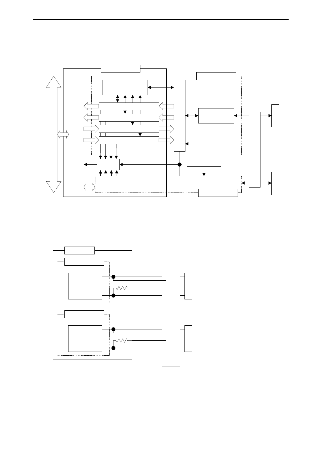
3.3 Circuit Diagram
FPGA
CAN controller
arbitration circuit
Channel 1
Error status FIFO
Receive message FIFO
Pseudo message transmit control
CardBus
Control circuit
CardBus bridge circuit
Transmit message FIFO
Interrupt
Same as channel 1
3.4 External Input/Output Circuit
The figure below shows the external input/output circuit of the CBI-4852A.
CBI-4852A
Channel 1
CAN
Transceive r
PCA82C250
CANH1
CANL1
:
CAN controller
OSC 24 MHz
CN1
CAN
transceiver
Channel 2
CN1CN2
PC card connecto
Branch cable connector
Channel 2
CAN
Transceive r
PCA82C250
CANH2
CANL2
JKC-4851
CN2
PC card connecto
Branch cable connector (with terminating resistor)
Interface Corporation -8-
Page 11
MCA-E4852A Ver. 1.1
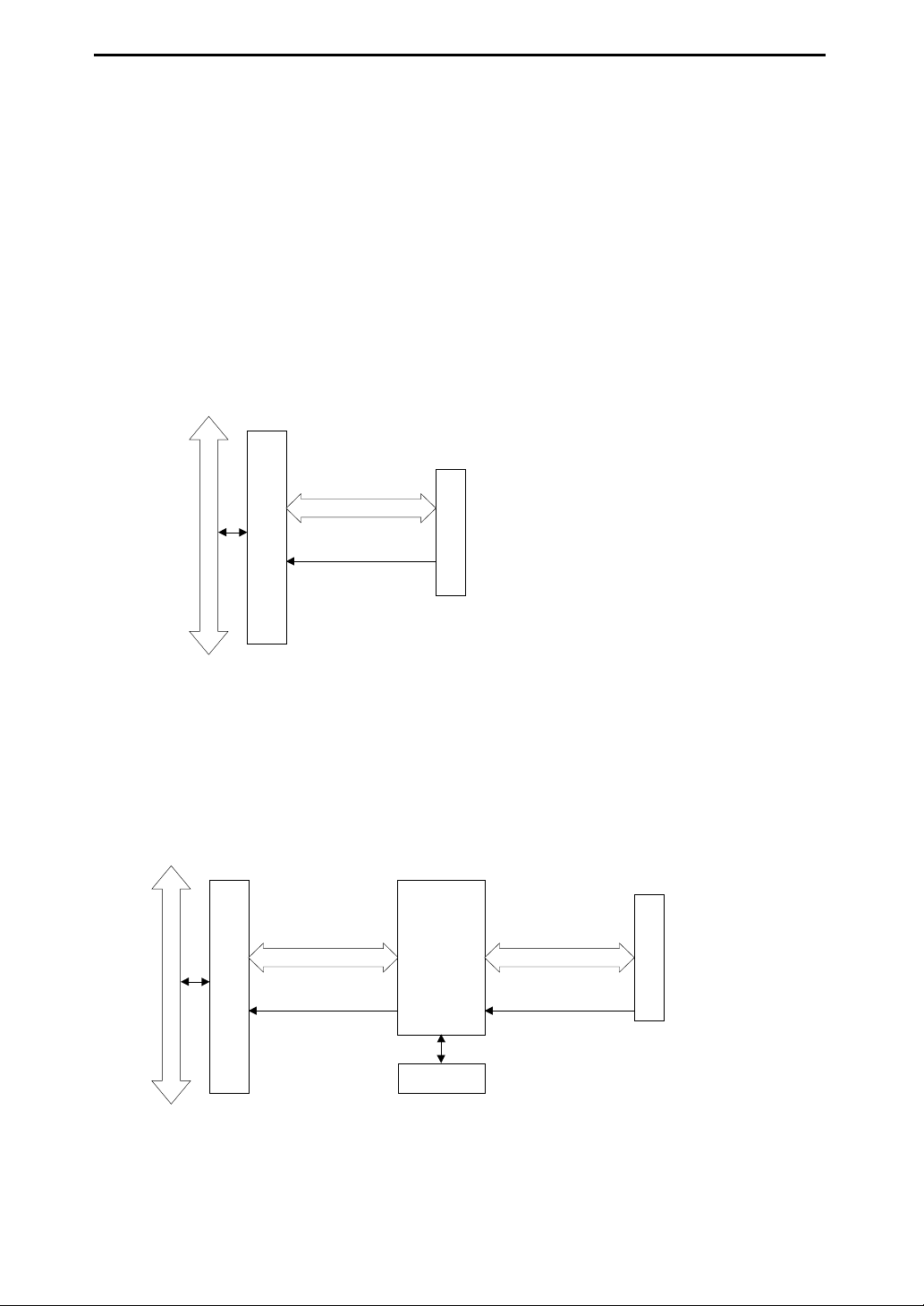
3.5 CAN Controller Access
3.5.1 Basic Mode
The CBI-4852A can directly access all registers of the SJA1000 CAN controller. Moreover, an interrupt
request is issued for CardBus by the controller interrupt signal. Basic CAN mode and Peli CAN mode are
selectable.
• Basic CAN mode
It is the mode with the conventional PCA82C200 CAN controller (Royal Philips Electronics or
equivalent) and compatibility. The contents of a register and arrangement are the same.
• Peli CAN mode
It is the mode which added the extended function to the conventional CAN controller. It has such
function as 64 bytes of receive FIFO. More advanced communications control can be performed by using
an extended function.
Register access
CardBus
Control circuit
CardBus bridge circuit
Interrupt
CAN controller
3.5.2 FIFO Mode
In FIFO mode, the following functions are provided:
• Transmit message FIFO or pseudo message transmit for transmit
• Reseive message FIFO for receive
• Error status FIFO for error control
These modes require accesses to the CAN controller in the internal control. Therefore, direct accesses to some
part of registers of the CAN controller are forbidden.
FIFO
Register access
CardBus
Control circuit
CardBus bridge circuit
Interrupt
control
circuit
Register access
Interrupt
CAN controller
FIFO
Notes:
• When using our driver software, this card can be used regardless of CAN controller modes. Moreover,
driver software cannot control CAN controller directly.
• Do not use our driver software. When controlling this card directly, refer to the data sheet of the SJA1000
CAN controller or I/O map.
-9- Interface Corporation
Page 12
MCA-E4852A Ver. 1.1
Chapter 4 External Connections
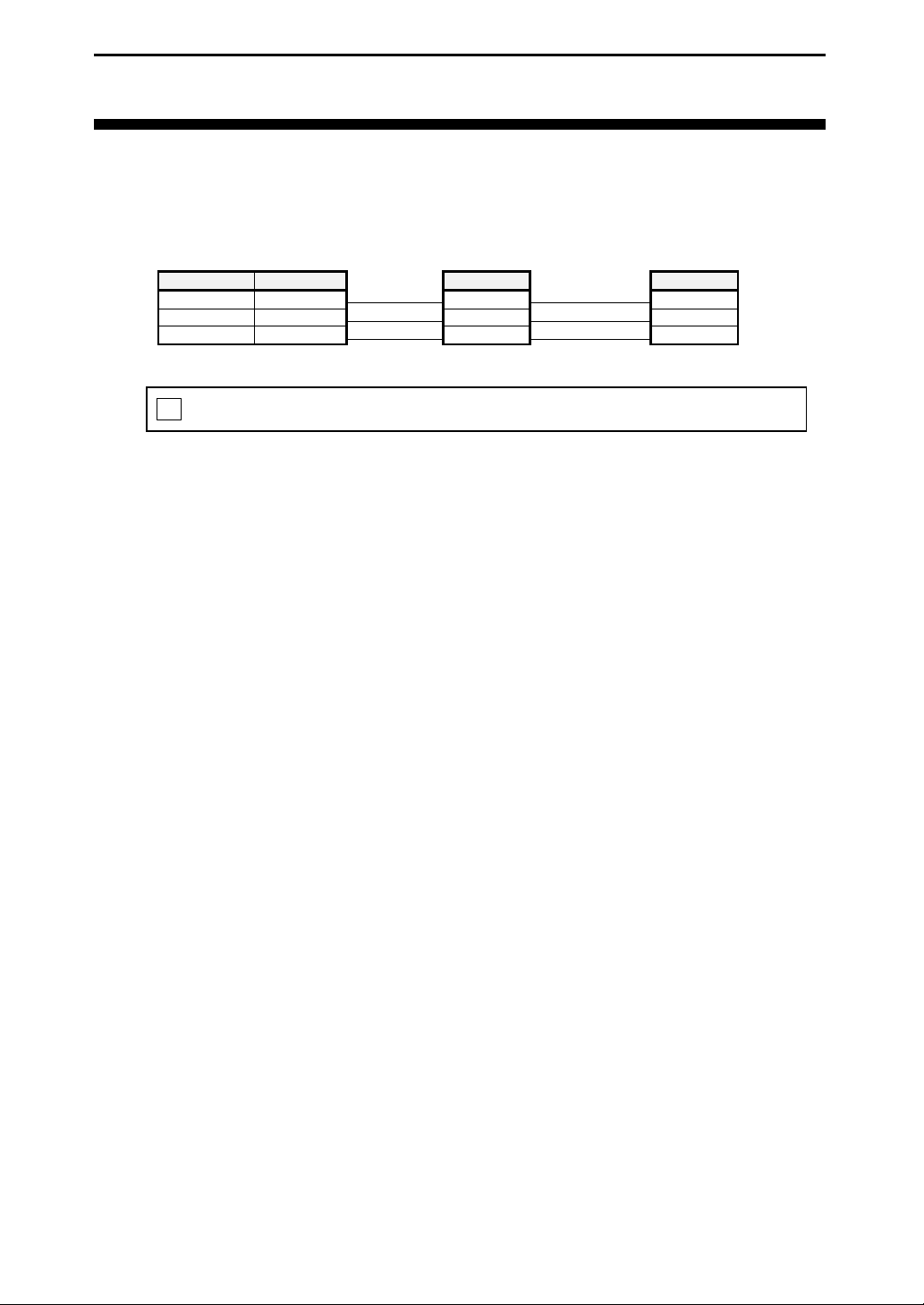
4.1 Example Connection
The figure below shows example connection of the CBI-4852A.
CBI-4852A
(with terminator)
Pin Number Signal
2CANL
7CANH
3GND
Other CAN interfaces
(without terminator)
Signal
CANL
CANH
GND
Other CAN interfaces
(with terminator)
Signal
CANL
CANH
GND
! To avoid an error, connect a CAN Interface with terminator to the both ends of the network.
Interface Corporation -10-
Page 13
MCA-E4852A Ver. 1.1
Chapter 5 Installation
BE SURE TO ELIMINATE STATIC ELECTRICITY OF YOUR BODY BEFORE YOU INSTALL
OR REMOVE THIS PRODUCT.
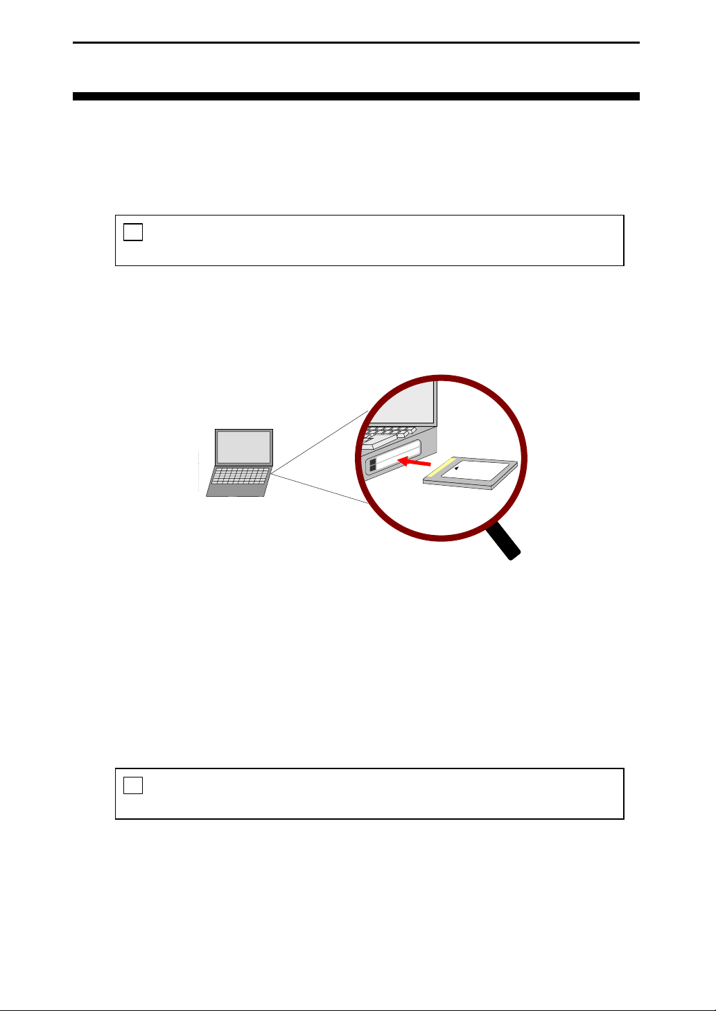
5.1 Card Installation
When you install this product in your system, read the manual of your system which refers to the PC card slot.
!
Be careful of the insert direction when you insert this product into your system to avoid system
damage.
1. Make sure that the system is turned off and the power cable is unplugged.
(This card corresponds to Hot Swap. You can insert this card when the system turns on.)
2. Insert the card into the PC card slot in your system.
3. Plug in the power cord, and turn on the system.
5.2 Driver Software Installation
Refer to our Web site for the Help of each optional software when you install and use it.
5.3 Card Uninstallation
The method of removing PC card from your system differs depending on each system. Please read the manual
of your system.
Do not remove this product when accessing to the external equipment. Your system may not operate
!
correctly.
-11- Interface Corporation
Page 14
MCA-E4852A Ver. 1.1
5.4 Multiple CardBus Cards
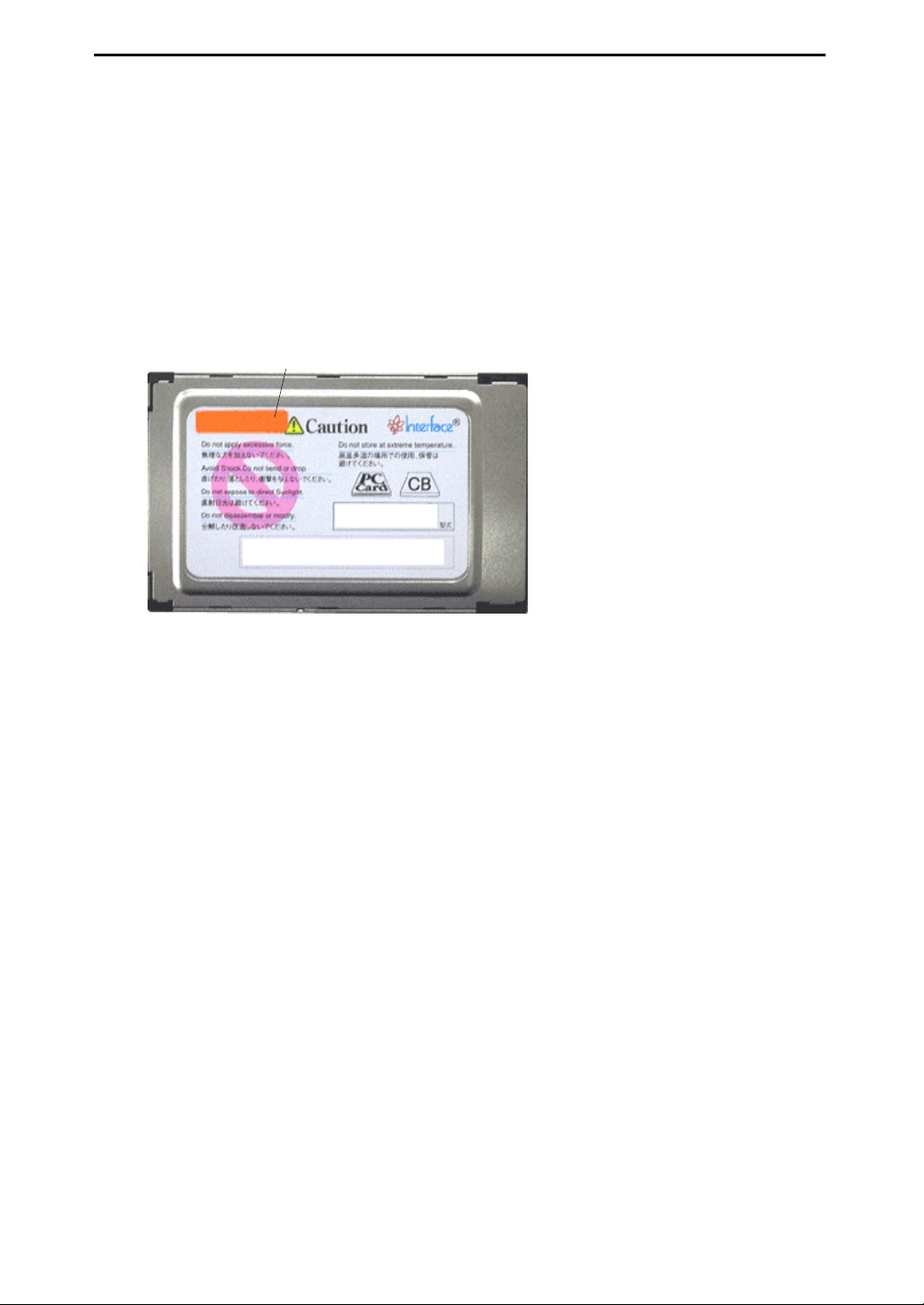
When using multiple cards in one system, it is required to write the CardBus ID number to the ROM in the card.
The CardBus ID configuration utility program in the software can configure the number. Refer to Help files for
more details.
Notes:
• Write the configured CardBus ID number on the back side of each card to easily confirm the number.
• Please download and use the newest version about software.
The following example shows the CardBus ID number is “0.”
Color seal
0
Back side of the card
Interface Corporation -12-
Page 15
Chapter 6 Glossary
6.1 List of Definitions
The list below explains a selection of technical terms used in this manual.
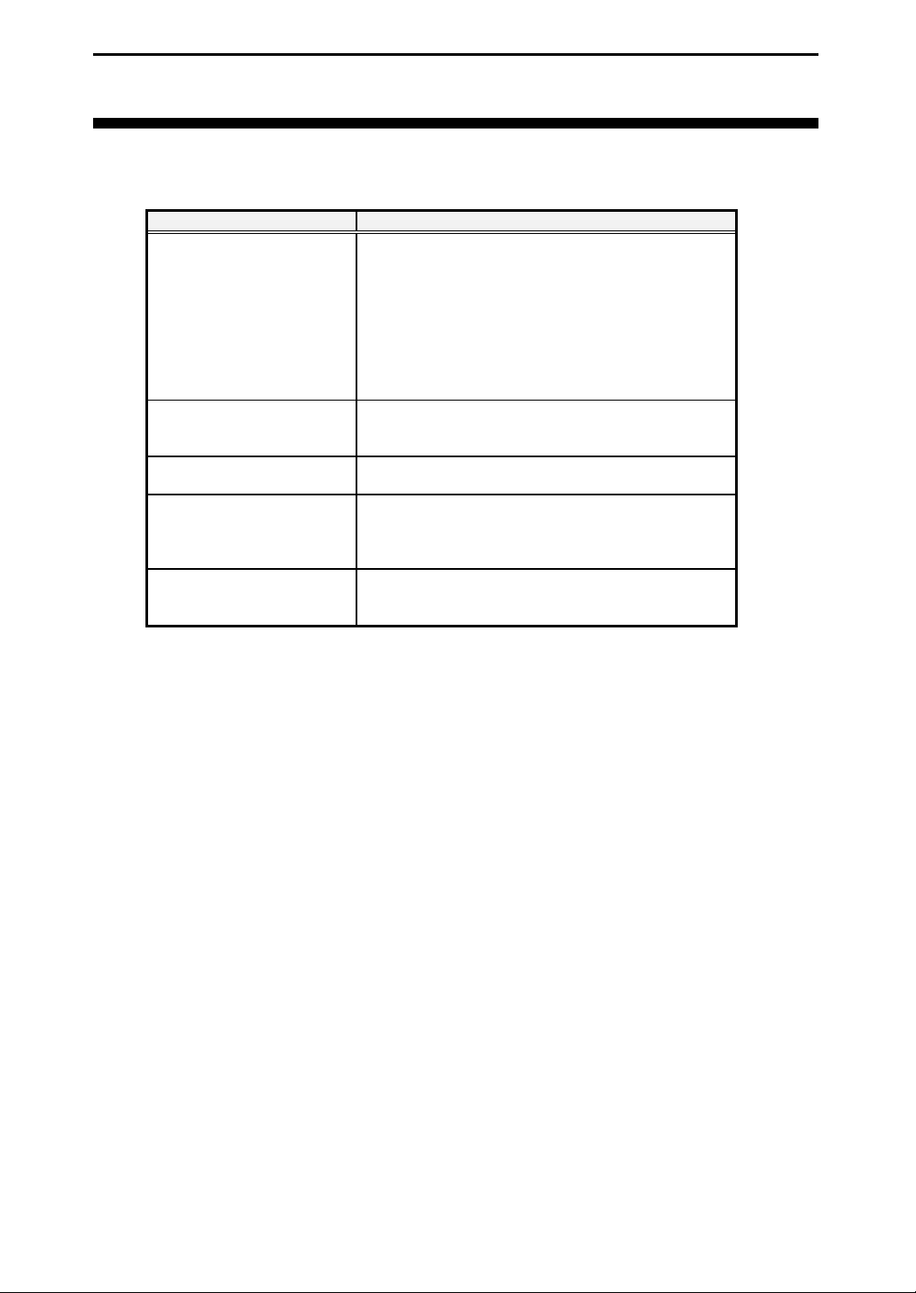
Term Definition
CAN CAN is an acronym for Controller Area Network.
Standardized by ISO as a serial communications protocol,
CAN was developed by the German electrical equipment
manufacturer, BOSCH, for use in automotive networks.
After being regulated by ISO, CAN soon became the
de-facto standard in the automobile industry.
CAN technology is now used in various other fields such as
factory automation, agriculture, medical equipment, nautical
craft, and also DeviceNet.
ISO11898-2 The high-speed CAN communications standard. The bit rate
range is between 125 kbps and 1 Mbps. It may not be
connected to a fault-tolerant CAN bus.
Terminating resistor The resistor used in order to minimize reflection of an
electric signal, also called a terminator.
Dominant A logical 0 is represented by the dominant bit. When a
dominant bit and a recessive bit are output simultaneously
by two different drivers on the same bus, only the dominant
bit is observed on the bus signal line.
Recessive A logical 1 is represented by the recessive bit. When the bus
is in the idle state, a recessive bit is observed on the bus
signal line.
MCA-E4852A Ver. 1.1
-13- Interface Corporation
Page 16
MCA-E4852A Ver. 1.1
Chapter 7 Notes for Users
For your safety, follow all warnings and instructions described in this manual.
7.1 Caution, Periodic Inspections, and Storage
Failure to follow this warning may result in electric shock, burns, serious injury, and in some cases, even cause
death.
Warning!
!
z Keep this product away from flammable gases.
Use this product only under the conditions as shown below.
Environmental Specifications
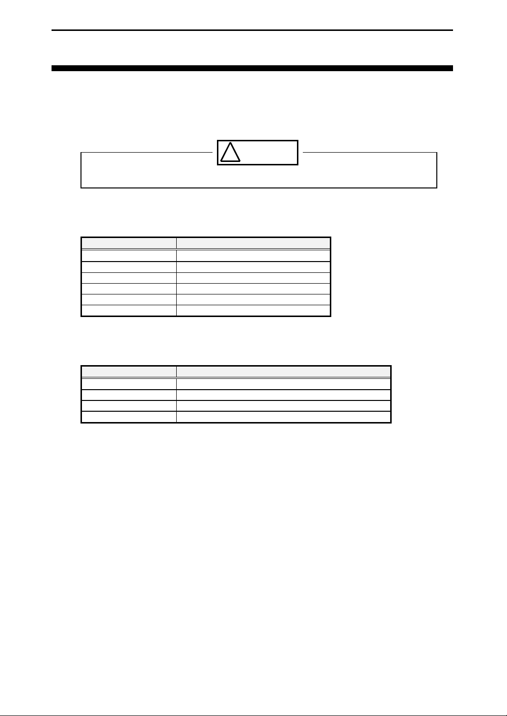
Parameter Specification
Temperature Range
Relative Humidity Range 20% to 90% (non-condensing)
Dust Typical office environment
Corrosive Gas None
Noise Far from power source and its wiring
Voltage Requirements CardBus specification: +3.3 Vdc (+/-0.3 V)
0 °C to 50 °C
The following inspections should be carried out on this card periodically.
Periodic Inspections
Item Checkpoint
Cable Connections Be sure that all connectors and cables are installed correctly.
Card Edge Check for dirt or corrosion.
Connector Contacts Check for dirt or corrosion.
Card Surfaces Surface should be free of dust and foreign matter.
Interface Corporation -14-
Page 17
MCA-E4852A Ver. 1.1
d
TO AVOID DAMAGE TO THE CARD AND POSSIBLE INJURY, TAKE APPROPRIATE
PRECAUTIONS AS DESCRIBED BELOW WHEN HANDLING IT.
Caution!
! This card should be stored exactly the same way as when it was received. Proceed as follows:
1. Put the card back in its PC card case.
2. Wrap the PC card case with the original packing material.
3. Avoid excessive humidity.
4. Do not expose the card to the direct rays of the sun.
5. Store the card at room temperature.
!
Do not modify the card. Interface Corporation assumes no liability for any malfunctions resulting
from users’ unauthorized modification of the card.
Take measures to avoid and minimize shock, vibration, magnetic fields, and static electricity in the
!
storage or operating environment of this card.
!
Make sure that the card is disconnected from the cable before inserting or removing any cards.
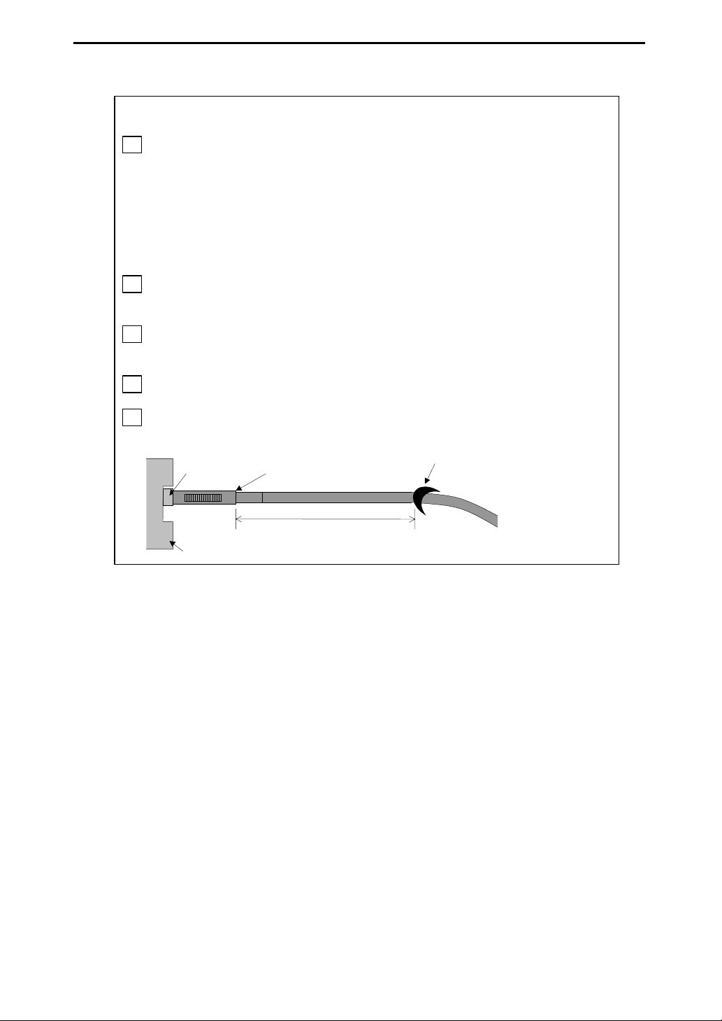
Please keep the attached cable in a horizontal position for approximately 10 cm from the card
!
connection part as below, and fix it not to move, even if stress starts.
Fixe
CBI-4852A Attached cable
computer
Approximately 10 cm
-15- Interface Corporation
Page 18
MCA-E4852A Ver. 1.1
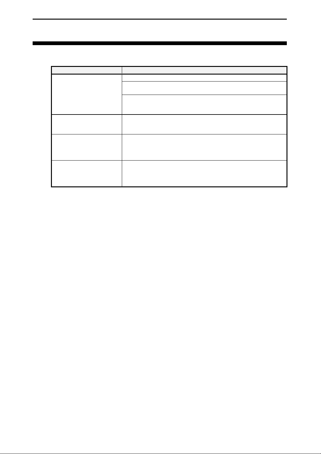
Chapter 8 Troubleshooting
8.1 Checkpoints
Problem Solution
Data cannot be transferred
correctly.
Communications are not
reliable. Transmit/receive
errors occur.
The computer does not
recognize this board.
The computer does not
response after Standby mode.
(Input and output are
disabled.)
Double-check all cable connections.
Set up your equipment to meet the timing characteristics of this board, such
as data setup time, and input/output response time.
If the power requirements exceed the system power budget, the circuits on
the board or connected external circuits cannot be driven properly. Prepare
an external power supply for your PCI board.
Check whether the selected terminating resistor is suitable for your system.
Refer to “3.4 External Input/Output Circuit,” page 8.
Use the PCI device viewer (BPF-0801) to examine the CardBus card board
on your computer. Please send the result to our Technical Support Center
by fax or e-mail. The PCI device viewer may be downloaded from our Web
site free of charge.
Set the System standby setting to “Never”.
Interface Corporation -16-
Page 19

-Index-
MCA-E4852A Ver. 1.1
B
Basic CAN mode .................................................. 9
C
CAN..................................................................... 13
CAN bus moitor.................................................... 3
CAN controller.................................................. 6, 9
CAN protocol........................................................ 3
CAN transceiver.................................................... 6
Card installation .................................................. 11
Card uninstallation .............................................. 11
D
Dominant............................................................. 13
Driver software uninstallation ............................ 11
E
Electric characteristics........................................... 7
Environmental specifications ............................. 14
F
FIFO....................................................................... 3
G
GPC-4851.............................................................. 4
GPD-4851.............................................................. 4
GPF-4851 .............................................................. 4
GPH-4851.............................................................. 4
I
ISO11898-2............................................................3
L
Linux ......................................................................4
O
Optional products...................................................4
P
PCA82C200...........................................................9
PCA82C250.......................................................3, 6
PCI device viewer................................................16
Peli CAN mode......................................................9
Pseudo message .................................................3, 9
R
Recessive..........................................................7, 13
RTLinux.................................................................4
S
SH-Linux................................................................4
SH-RTLinux ..........................................................4
Signal description ..................................................5
SJA1000.............................................................3, 6
T
Terminating resistor.............................................13
-17- Interface Corporation
Page 20
For Assistance:
Please visit our Web site (www.interface.co.jp) or send a fax (0120-621553(in Japan)) or e-mail
([email protected]) to the Technical Support Center.
We recommend you to ask questions from our Web site to shorten the answering time.
If the problem is urgent, please consult the Sales Information Center.
When you contact us, we need the information on the Technical Support Form provided with this manual plus the
information listed below so we can answer your questions as quickly as possible.
Computer Environment
Description of The Problem
Technical support is available during business hours.
We provide a product rental service so you can evaluate our product prior to purchase.
Inquiries Refer to Phone FAX
Product Rental Service Technical Support Center 082-262-1630 (in Japan) 082-262-1552 (in Japan)
Distributors,
Shipping Date,
Prices, Others
Sales Information Center
Computer brand and model, specific operating system,
software configuration, other interface boards installed if any.
Situations where the product was used.
0120-447213
(in Japan)
E-mail : [email protected]
0120-458257
(in Japan)
Repair and Maintenance
The company will, at its option, replace its product, which the company, upon inspection, shall determine to be
defective in material and/or workmanship. If the product is obviously damaged or defective, please return it using
procedures outlined below.
1. Fill out the Repair Request Form. Describe hardware configurations of the board and malfunction in detail.
2. Fax the Repair Request Form to the Technical Support Center.
3. We will send you a repair quotation by return fax.
4. Carefully repack the damaged product, enclosing the Repair Request Form, and forward it (shipping prepaid)
to the repair group, at our Oita Plant (address shown below).
When the damage or defect is not obvious, please contact the Sales Information Center or our Technical Support
Center.
Be aware that depending on the extent and type of damage, the unit may not be economically repairable. If so, we
will notify you immediately.
Receiver’s Address
Contact Information
Repair Group, Oita Plant, Interface Corporation
1428, Shimobaru, Aki-machi, Higashikunisaki-gun, Oita, 873-0231 Japan
Technical Support Center
Phone: 082-262-1630 (Available during business hours)
FAX: 082-262-1552
Visit our Web site (www.interface.co.jp) for:
Technical Support Frequently asked questions, related technical terminology
Product Information The latest information about our products; specifications, product selection guides, etc
Useful Information Discount information, rental information, distributors
Downloads Service Drivers, technical documents such as I/O port maps, sample programs, and user’s
manual data.
The design and contents of the web site are under constant review. Therefore, there might be some changes in its
design and contents.
is a trademark of Interface Corporation (under application).
is a collective mark of Japan Electronics and Information Technology Industries Association (JEITA).
Other product and company names are trademarks, registered trademarks, or servicemarks of their respective
owners.
2004 Interface Corporation
All rights reserved. No part of this publication may be reproduced or altered in any form or by any means without the
written permission of Interface Corporation.
Page 21

MCA-E4852A Ver. 1.1 Vol. 1/1
 Loading...