

Page 1
The Leader in Force Measurement
INTERFACE • 7401 E. Butherus Drive, Scottsdale, AZ 85260 • PHONE: (480) 948-5555 • FAX: (480) 948-1924
www.interfaceforce.com • Email: [email protected] • ORDER TOLL-FREE 1-800-947-5598
JunctionBox
Rev B
05/21/18
JB104SS
Junction Box
Page 2
The Leader in Force Measurement
INTERFACE • 7401 E. Butherus Drive, Scottsdale, AZ 85260 • PHONE: (480) 948-5555 • FAX: (480) 948-1924
www.interfaceforce.com • Email: [email protected] • ORDER TOLL-FREE 1-800-947-5598
JunctionBox
Rev B
05/21/18
1
Mounting the Small Junction Box
The junction box should be mounted in a location that is convenient for servicing and
away from standing water. Try to mount the enclosure in a location so that the load cell
cables need not be cut, nor length added. Load cell output is temperature
compensated for the supplied cable length. Altering that length can change the cell’s
signal output.
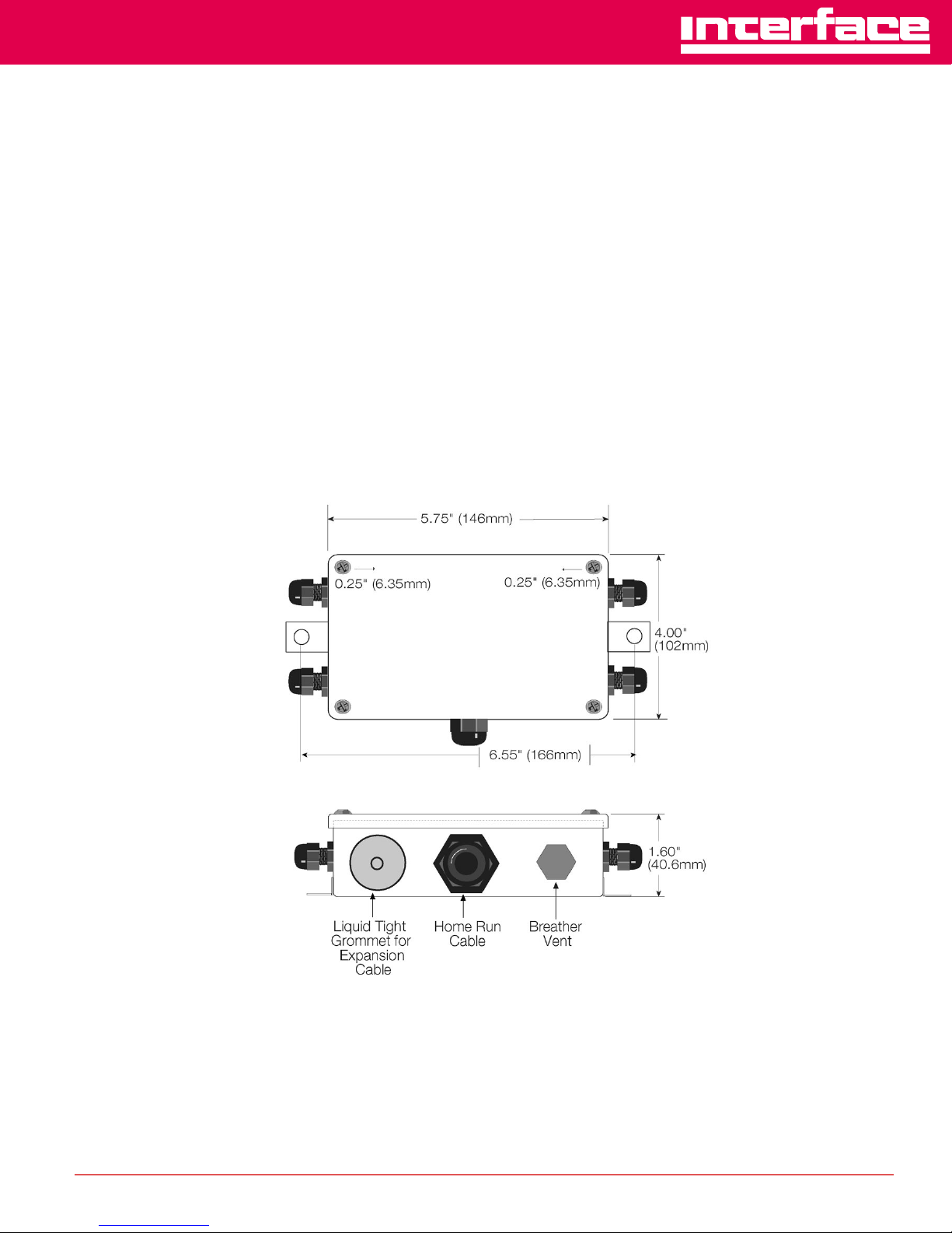
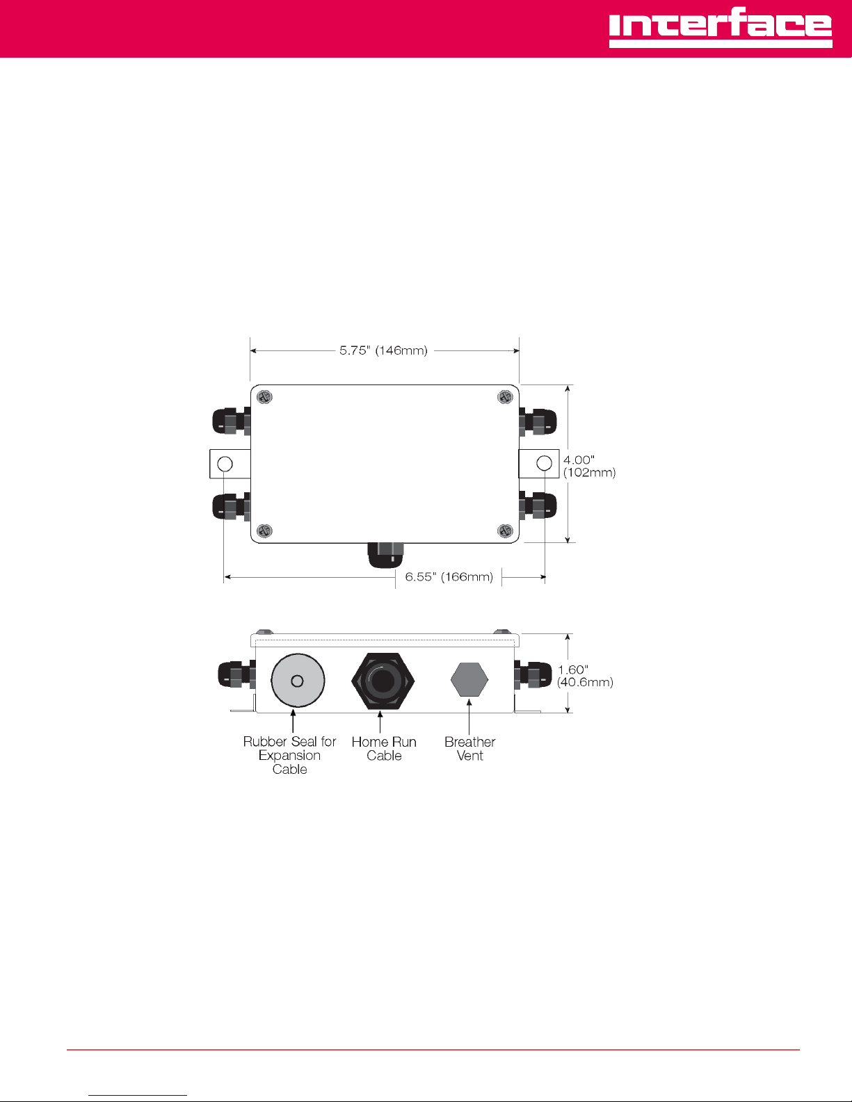
Depending on the mounting surface, the JB104SS enclosure can be attached using
two pan-head screws, bolts, or other suitable fasteners. Figure 1 below shows the
dimensions for mounting the enclosure
Figure 1: JB104SS Enclosure Dimensions
Page 3
The Leader in Force Measurement
INTERFACE • 7401 E. Butherus Drive, Scottsdale, AZ 85260 • PHONE: (480) 948-5555 • FAX: (480) 948-1924
www.interfaceforce.com • Email: [email protected] • ORDER TOLL-FREE 1-800-947-5598
JunctionBox
Rev B
05/21/18
2
Wiring the Junction Box
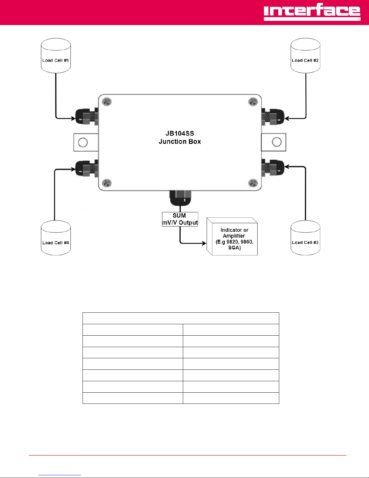
The JB104SS junction box model has been designed to connect and trim up to four
load cells per board. However it is possible to use this box with other combinations.
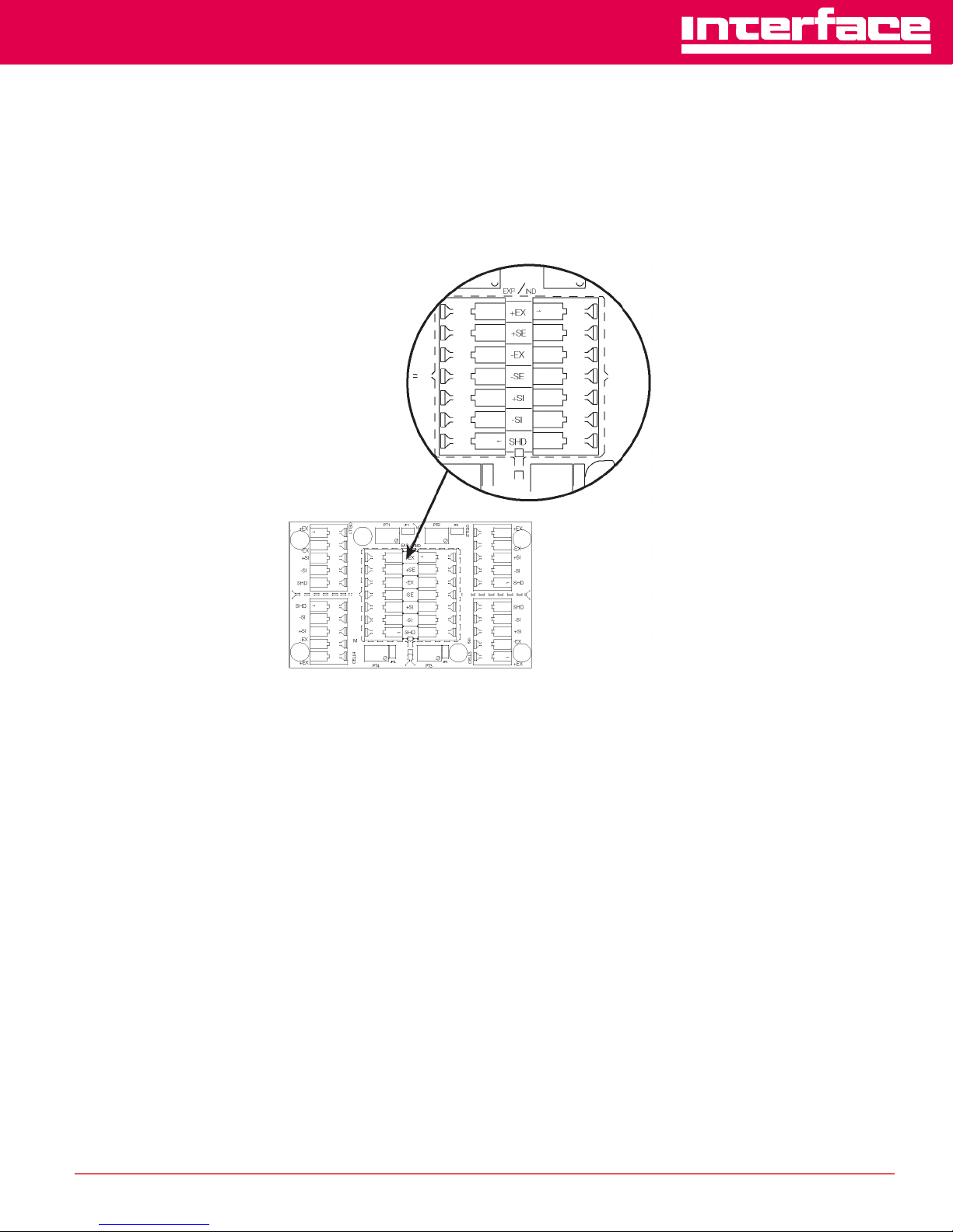
Use the expansion port on the main board (shown below), to connect multiple junction
boxes in series to accommodate applications that have more than four load cells.
Figure 2: Expansion Port Location
After determining the wiring pattern, route the load cell cables through the cord grip
assemblies and leave the grips loose until final closure. Before connecting load cell
wires to the terminals, strip the wire insulation back 1/4" to expose the wire. The
spring-loaded terminals will accommodate 12 to 28 gauge wire. To connect the load
cell wires to the appropriate connectors, push in the quick-connect lever with a small
screwdriver. While holding in the lever, insert the appropriate wire into the exposed
wire opening. Release the screwdriver to allow the spring-loaded gate to close and
lock the wire in place.
The indicator terminal strip is used to connect the main cable to the indicator.
Determine the indicator’s load cell input connections from the operating manual. Run a
cable from your indicator terminal into the junction box through the larger cord grip and
make the connections on the indicator terminal using the same procedure as inserting
load cell cables to the appropriate connectors.
Page 4
The Leader in Force Measurement
INTERFACE • 7401 E. Butherus Drive, Scottsdale, AZ 85260 • PHONE: (480) 948-5555 • FAX: (480) 948-1924
www.interfaceforce.com • Email: [email protected] • ORDER TOLL-FREE 1-800-947-5598
JunctionBox
Rev B
05/21/18
JB104SS Wiring
Load Cell
Color
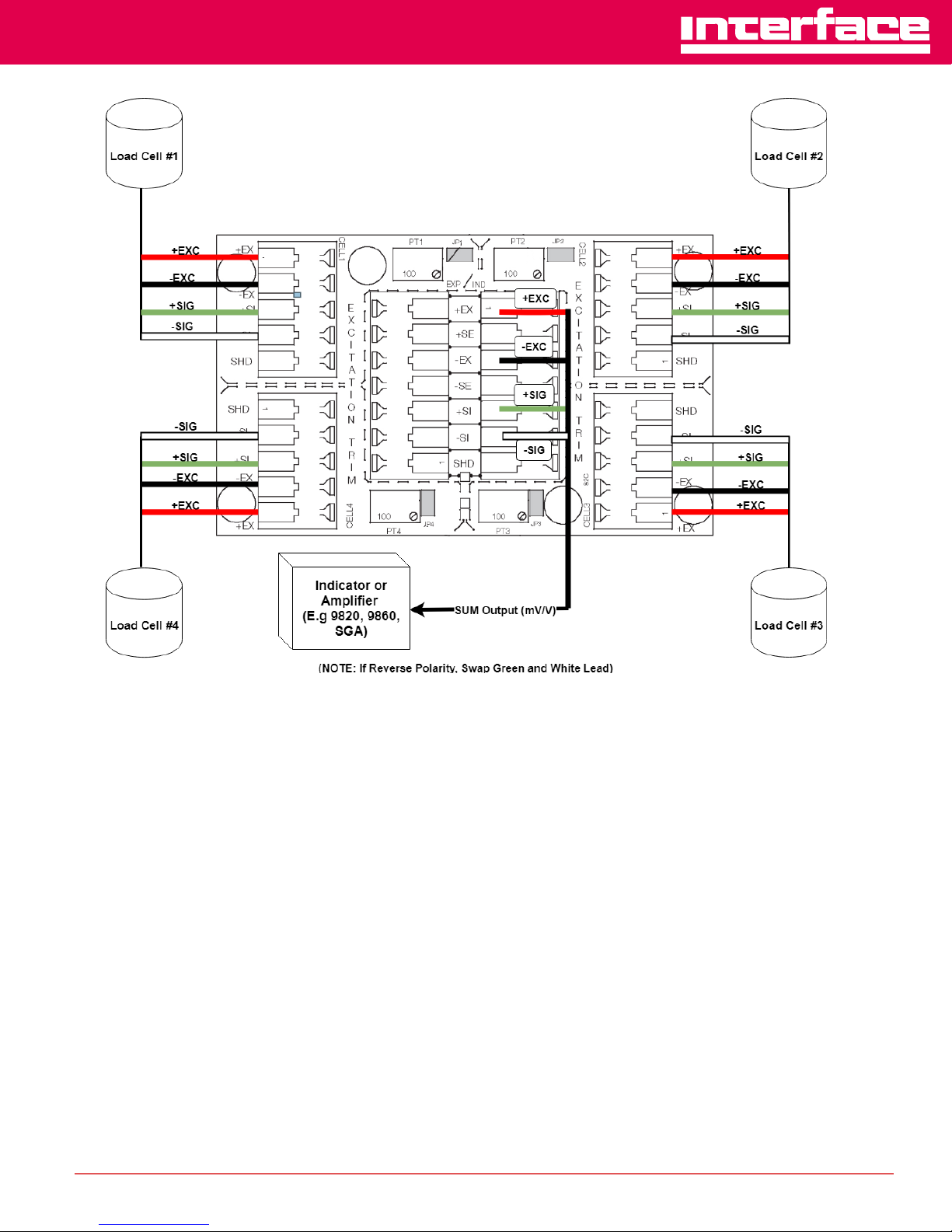
+EXC
RED
-EXC
BLK
+SIG
GRN
-SIG
WHT
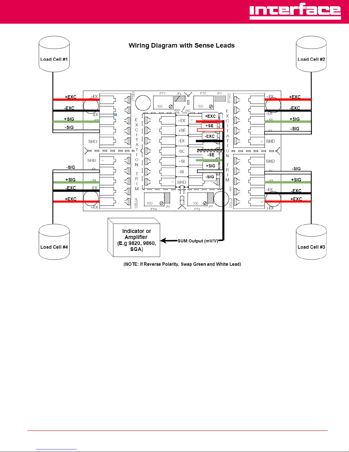
+SE
RED/WHT
-SE
BLK/WHT
Figure 3: Application Use
Figure 4: JB104SS Wiring
NOTE – If Tension Positive (Reverse Polarity) Swap Green and White Leads
Page 5
The Leader in Force Measurement
INTERFACE • 7401 E. Butherus Drive, Scottsdale, AZ 85260 • PHONE: (480) 948-5555 • FAX: (480) 948-1924
www.interfaceforce.com • Email: [email protected] • ORDER TOLL-FREE 1-800-947-5598
JunctionBox
Rev B
05/21/18
Figure 5: Wiring Diagram
Page 6
The Leader in Force Measurement
INTERFACE • 7401 E. Butherus Drive, Scottsdale, AZ 85260 • PHONE: (480) 948-5555 • FAX: (480) 948-1924
www.interfaceforce.com • Email: [email protected] • ORDER TOLL-FREE 1-800-947-5598
JunctionBox
Rev B
05/21/18
Figure 6: Wiring Diagram with Sense Leads
Page 7
The Leader in Force Measurement
INTERFACE • 7401 E. Butherus Drive, Scottsdale, AZ 85260 • PHONE: (480) 948-5555 • FAX: (480) 948-1924
www.interfaceforce.com • Email: [email protected] • ORDER TOLL-FREE 1-800-947-5598
JunctionBox
Rev B
05/21/18
3
Trimming Procedure
Trimming is a process of equalizing the output from multiple individual load cells. If
needed, load cell output can be individually trimmed with potentiometers.
Whenever a substantial amount of trim (more than 5% of normal output), seems
necessary to equalize output check for other possible problems. The best trim is
always the least amount of trim. When all errors except the cell mismatch and cable
extensions or reductions have been corrected, continue with the trimming.
3.1
Excitation Board Trimming Procedure
Use the following steps to properly trim the JB104SS junction box.
1.
Determine the number of load cells needed.
2.
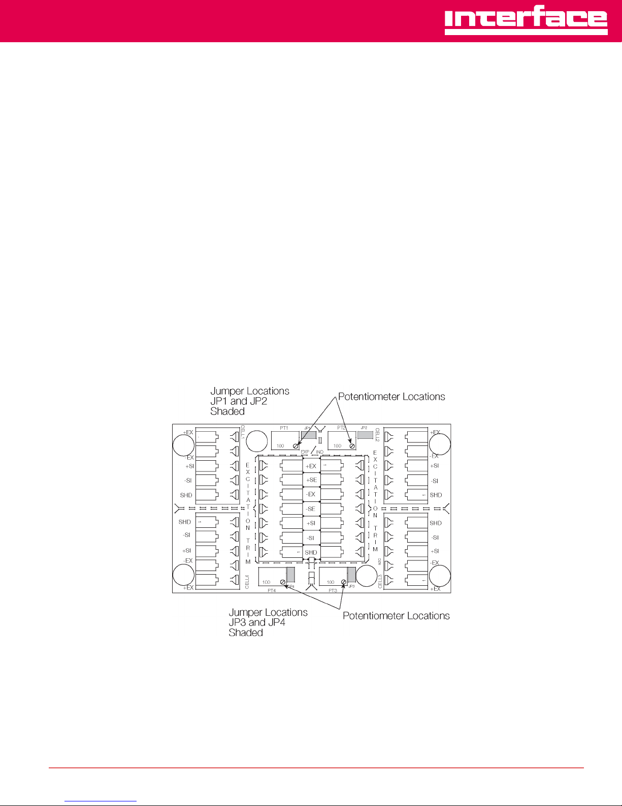
Make sure jumpers have been removed to enable trimming of the desired cells
corresponding to each load cell in use. See Figure 3 for the location of jumpers
JP1, JP2, JP3 and JP4. Note that jumpers must be removed to enable trimming
on the excitation board.
3.
Set all potentiometers fully clockwise to give maximum signal output from each
cell (see location of potentiometers below).
Figure 7: Excitation Main Board
Page 8

The Leader in Force Measurement
INTERFACE • 7401 E. Butherus Drive, Scottsdale, AZ 85260 • PHONE: (480) 948-5555 • FAX: (480) 948-1924
www.interfaceforce.com • Email: [email protected] • ORDER TOLL-FREE 1-800-947-5598
JunctionBox
Rev B
05/21/18
4.
Zero the indicator and place calibrated test weights over each load cell in turn.
The amount of test weights to be used will depend on the scale configuration; for
specific recommendations, refer to Handbook 44 Field Manual, published by the
Institute for Weights and Measures. For a four-cell platform, it’s recommended
using 25% of scale capacity.
5.
Record the value displayed on the indicator after the test weight is placed in turn
on each corner (directly over the load cell) without allowing the weight to
overhand the sides. Allow the scale to return to zero each time to check for
friction or other mechanical problems. Select the load cell which has the lowest
value as your reference point. This cell will not be trimmed.
6.
Replace the same test load over each cell in turn. Using the corresponding
potentiometer, trim each cell down to equal the reference load cell. As corner
corrections are somewhat interactive, check all cells again for repeatability. If
necessary, repeat steps 4 and 5.
7.
Pull excess cable out of the enclosure and tighten the cord grip assemblies with
a wrench. To be watertight, each cord grip must be tightened so the rubber
sleeve begins to protrude from the hub.
8.
Unused hubs must be properly plugged to prevent moisture entry. If extra hole
plugs are needed please consult factory.
9.
Remove the desiccant from the plastic bag, and insert the desiccant bag into the
junction box before closing. Inspect the desiccant during normal service and
change desiccant as needed.
10.
Replace the cover and tighten the cover screws in an alternating pattern to be
certain the gasket is compressed equal in all locations.
 Loading...