

Interface BX8-HD15, BX8-HD15-CAN, BX8-HD15-EC, BX8-HD44-EC, BX8-HD44-CAN Operating Manual
...Page 1
Interface Inc. ● 7401 East Butherus Drive, Scottsdale, Arizona 85260 USA ● Phone 480.948.5555 ● Fax 480.948.1924
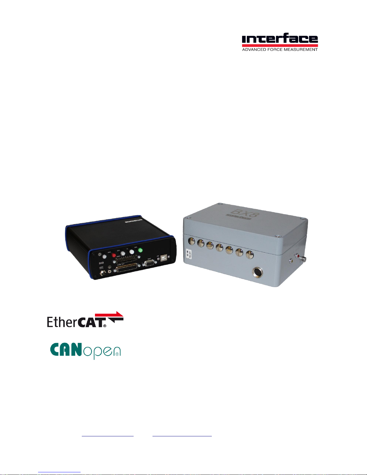
8-Channel Measuring Amplifier BX8
Operating Manual
15-247 Version 7E
Page 2
Interface Inc. ● 7401 East Butherus Drive, Scottsdale, Arizona 85260 USA ● Phone 480.948.5555 ● Fax 480.948.1924
Page 2 of 39
Measuring Amplifier BX8
Description
The 8-channel measuring amplifier BX8 is characterised by particularly high resolution at
data frequencies of 1 Hz to 48000 Hz. The 8 channels are acquired simultaneously.
Versions
Type
Sensor Input
Signal-Output
BX8-HD15
8x 15-Pin HD D-Sub
1xUSB, UART, Analog, Digital-I/O
BX8-HD15-EC
8x 15-Pin HD D-Sub
1xUSB, EtherCat, Analog, Digital-I/O
BX8-HD15-CAN
8x 15-Pin HD D-Sub
1xUSB, UART, CAN, Analog, Digital-I/O
BX8-HD44
4x 44-Pin HD D-Sub
1xUSB, UART, Analog, Digital-I/O
BX8-HD44-EC
4x 44-Pin HD D-Sub
1xUSB, EtherCat, Analog, Digital-I/O
BX8-HD44-CAN
4x 44-Pin HD D-Sub
1xUSB, UART, CAN, Analog, Digital-I/O
BX8-AS
1x 24-Pin M16, screw terminal
1xUSB, UART, Analog, Digital-I/O
BX8-AS-EC
1x 24-Pin M16, screw terminal
1xUSB, EtherCat, Analog, Digital-I/O
BX8-AS-CAN
1x 24-Pin M16, screw terminal
1xUSB, UART, CAN, Analog, Digital-I/O
8-channel measuring amplifier
8x input configurable full, half, quarter bridges, 120- 350- 1000 Ohm, PT1000, ±10V
Outputs 1x USB Port, 8x analog output, ±10V, 4...20mA configurable
16x digital in- and output
Galvanic isolation: analog-input, analog-output, digital-IO, 1x UART, USB
Options : EtherCat, CANbus/CANopen
8x 48kS/s simultaneous sampling
6-wire technology, bridge supply 2.5V, 5.0V, 8.75V configurable
Automatic configuration of analog and digital filters by specifying the data frequency
Additional Digital Filters FIR 14th order and IIR 4th order are individually configurable
Step response of the filter configuration can be viewed in software
Resolution < 20 nV/V
Page 3
Interface Inc. ● 7401 East Butherus Drive, Scottsdale, Arizona 85260 USA ● Phone 480.948.5555 ● Fax 480.948.1924
Page 3 of 39
Interfaces
Communication interfaces such as USB port or EtherCAT or CANbus are available. The
device has 8 configurable Analog Outputs (±10 V and 4...20 mA among others). UART
interface serves to control the measuring amplifier via the Raspberry PI.
Features
There are 8 Analog Inputs available. They are individually configurable as:
Strain gage input for full bridges in 4 and 6 wire technology or
Strain gage input for half bridges or
Strain gage input for quarter bridges 120 ohm, 350 ohm, 1K Ohm or
Single-ended input ±10 V or
Input for PT1000 temperature sensor.
The strain gage supply voltage can be switched between 8.75 V, 5.00 V and 2.5 V, Input
sensitivities 2 mV/V, 3.5 mV/V or 7 mV/V.
Bridge supply voltage
Resulting input sensitivity
8.75V
2mV/V
5V
3.5mV/V
2.5V
7mV/V
Galvanic Isolation
The supply voltage UB+ UB- is galvanically isolated from the components for
analog input
analog output
digital inputs and outputs
interfaces
The isolation voltage is 50 V
UB+
Supply Voltage 12...28V DC
UB-
Ground Supply Voltage
GNDE
Ground Analog-Input
-Us
Negative Bridge Supply
GNDA
Ground: Analog-Output
GNDD
Ground Digital Input /Output
GNDU
Ground UART Port (“Raspberry PI Port“)
GNDR
Ground RS232 Port
Page 4
Interface Inc. ● 7401 East Butherus Drive, Scottsdale, Arizona 85260 USA ● Phone 480.948.5555 ● Fax 480.948.1924
Page 4 of 39
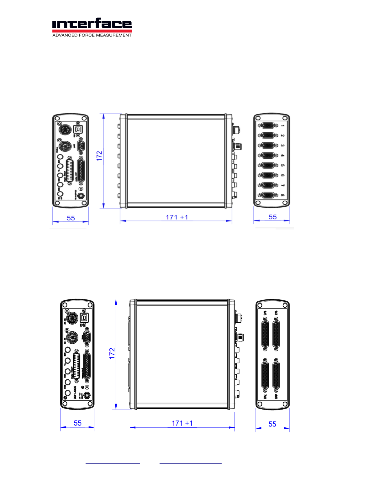
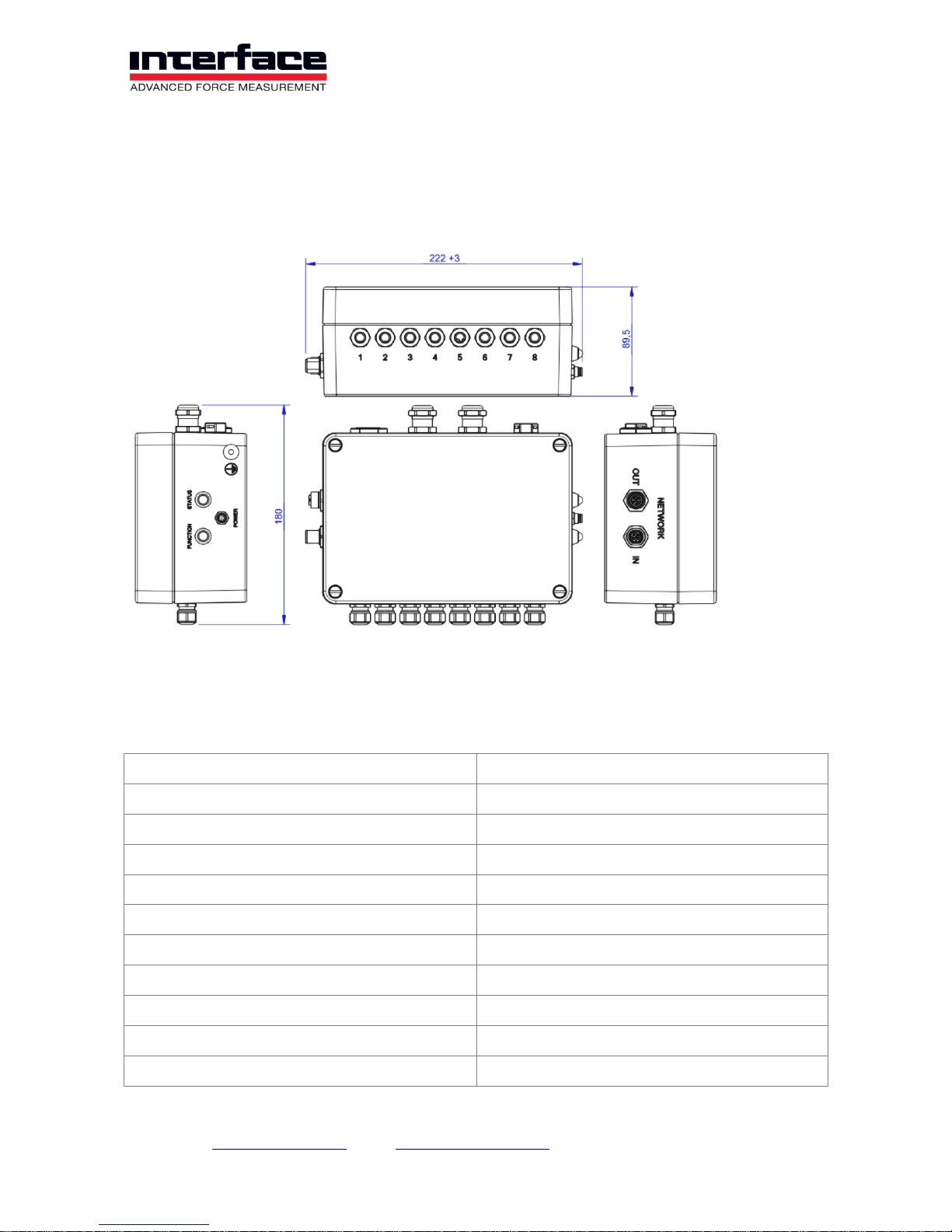
Dimensions
BX8-HD15
BX8-HD44
Page 5
Interface Inc. ● 7401 East Butherus Drive, Scottsdale, Arizona 85260 USA ● Phone 480.948.5555 ● Fax 480.948.1924
Page 5 of 39
BX8-AS
Technical Data
Analog Input
Accuracy class
0.05%
Number of analog inputs
8
Strain gage bridge input
Quarter, Half, Full Bridge
Input impedance
> 20M Ohm (300pF)
Common mode rejection DC
> 120 dB
Common mode rejection AC 100Hz
> 100 dB
Strain gage bridge completion
120 Ohm, 350 Ohm, 1K Ohm
Strain gage bridge supply
2.50 V, 5.00 V, 8.75 Volt
Total current across all channels
200 mA
Max. current per channel
60 mA
Input sensitivity
7 mV/V, 3.5 mV/V, 2 mV/V
Page 6
Interface Inc. ● 7401 East Butherus Drive, Scottsdale, Arizona 85260 USA ● Phone 480.948.5555 ● Fax 480.948.1924
Page 6 of 39
Accuracy class
0.05%
Input voltage
±10 V
Input resistance
10M Ohm
Input for PT1000 sensor
-230 °C ... +1500 °C
Excitation voltage PT1000
1.25 V
Digital Input / Digital Output
Number of in-/ outputs
16
Output
TTL (0V 5V), push-pull
total current across all channels
140 mA
max. load current per output
25 mA
Input
max. input voltage
5.5 V
min. input voltage
-0.5 V
Resistance Pull Up +5V
10K Ohm
Sampling period
40 mS
Analog Output
Number of analog outputs
8
Configuration of analog outputs
0...10V, -10V..+10V, 0...5V, -5V...+5V, 4...20mA
Supply
Supply voltage
12 V to 28 V
Power
< 12 W
Environmental data
Operating temperature
0 °C ... +50 °C
Power
< 12 W
Interfaces
USB
2.0 Full Speed
Devices class
Communication Device Class, HID (firmware
update only)
Page 7
Interface Inc. ● 7401 East Butherus Drive, Scottsdale, Arizona 85260 USA ● Phone 480.948.5555 ● Fax 480.948.1924
Page 7 of 39
UART
Level 3.3V, galvanically isolated;
auxiliary voltage 24V DC, 2A
EtherCat
Protocol: CoE device profile 404, Mailbox- and
buffered mode. Synchronization: HardwareLatching
CANbus
CANopen, device profile 404, 4x TxPDOs,
galvanically isolated
Resolution of Strain Gage Input
The resolution of the measuring amplifier depends on the adjusted input sensitivity. The
input sensitivity is coupled with the bridge supply voltage: 8.75V with 2.0 mV/V, 5V with 3.5
mV/V, 2.5V with 7 mV/V.
The excitation voltage with 8.75V is recommended only with sensors of minimum 1K Ohm
connecting resistance and enough construction size. For miniature sensors under 500g
weight the bridge supply of 8.75V may not be applied!
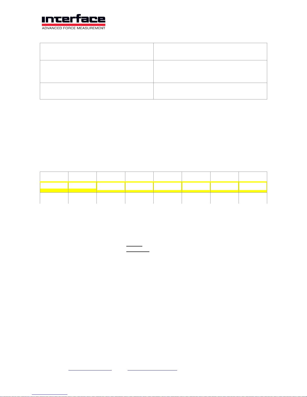
+Us
10 Hz
50 Hz
100 Hz
1 kHz
5 kHz
8 kHz
3.5 mV/V
5 V
2.0 105
1.2 105
8.0 104
2.5 104
1.0 104
8.0 103
2.0 mV/V
8.75 V
3.0 105
2.5 105
1.5 105
6.0 104
4.0 104
1.4 104
At a data frequency of 10 Hz the measuring range from 0 to +3.5 is divided in 2.0x10⁵
steps.
The noise amplitude is 17.5 nV/V.
At a sensor with rated force of 10 N and rated output of 0.5 mV/V the noise amplitude is
Page 8
Interface Inc. ● 7401 East Butherus Drive, Scottsdale, Arizona 85260 USA ● Phone 480.948.5555 ● Fax 480.948.1924
Page 8 of 39
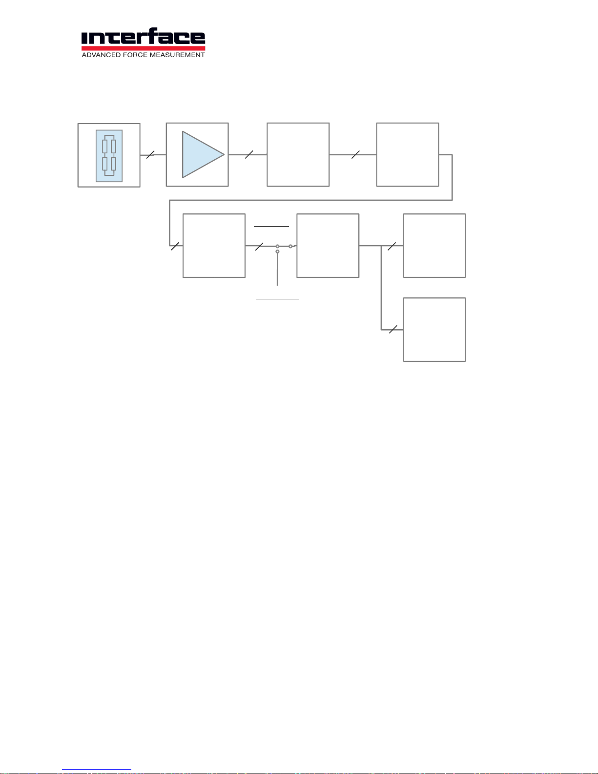
Signal flow
Digital Filters
The BX8 automatically selects the analog filter and the "decimating" averaging filter
depending on the data rate (samples per second) set by the user. The user must only
enter the desired number of samples per second to be supplied via the USB port or analog
outputs.
In addition, there are two adjustable digital filter: 1x FIR filter and IIR filter 1x. Each of
these digital filters can be set individually for each of the 8 input channels. In the
measurement data signal processing chain, the FIR filter is listed first, followed by the IIR
filter.
Finite Impulse Response Filters
The FIR filter is a low pass filter, wherein the filter order N, and the limit frequency fg can
be adjusted. The cutoff frequency is that signal frequency at which the signal is already
attenuated by -3 dB. This corresponds to a factor of about 0.7. Signals above this
frequency are attenuated further.
The filter order determines the maximum and minimum adjustable cut-off frequency fg in
terms of data rate Fa, and the steepness of the attenuation range. Higher orders have a
steeper slope, i.e. an increase in the signal frequency causes the attenuation to increase
faster. The so-called step response is slower at higher orders however, i.e. it always takes
N+1 measured values until the filter’s output value corresponds to the input value.
AD
Converter
48 kS/s / N
decimating
Filter
config.
IIR / FIR
Filters
USB
D/A
Converter
±10 V
4..20 mA
Analog
Filter
8 8 8
48kS /s
N
48 kS/ s
8
8 8
8
Fullscale
2
Page 9
Interface Inc. ● 7401 East Butherus Drive, Scottsdale, Arizona 85260 USA ● Phone 480.948.5555 ● Fax 480.948.1924
Page 9 of 39
Order
fg/Fa min in Hz
fg/Fa max in Hz
14
0.05
0.190
12
0.06
0.225
10
0.07
0.270
8
0.09
0.340
6
0.12
0.350
4
0.18
0.410
Infinite Impulse Response Filter
The digital filter is a so-called infinite impulse response filter (IIR) of fourth order.
Four different filter types can be set:
1. Low pass filter: Sensor signals at low frequency (including DC size with f=0) pass
through the filter, signals at a higher frequency are attenuated.
2. High pass filter: Sensor signals at low frequency (including DC size with f=0) are
attenuated, signals at a higher frequency pass through the filter. Note: Frequencies above
half of the measured data rate cannot be processed. The measuring amplifier includes an
Analog-to-digital sampling system, which in itself acts as a low pass.
3. Band pass filter: Signals are allowed to pass through within a frequency range, signals
which are above or below this range are attenuated.
4. Band stop filter (‘Notch filter’): Signals are attenuated within a frequency range, signals
which are above or below this range are allowed to pass through.
The cutoff frequency can be configured for low and high pass filters. The cutoff frequency
is the frequency at which the signal is already attenuated by -3 dB. This corresponds to a
factor of approx. 0.7. Frequencies lying above for low pass and lying below for high pass
will continue to be attenuated.
Two cutoff frequencies can be configured for band pass and band stop filters; the upper
and the lower. Attenuation by -3 dB also occurs here. The two cutoff frequencies may not
be the same. Signal frequencies lying between these are allowed to pass through for the
band pass filter, and are attenuated for the band stop filter.
The maximum (and also the minimum if need be) of each cutoff frequency is dependent on
the measured data rate. Cutoff frequencies can be set to (0.49 * measured data rate), i.e.
almost to half.
The filters can be individually configured for each channel and also switched on and off.
The configuration also remains the same for filters that have been switched off.
Page 10
Interface Inc. ● 7401 East Butherus Drive, Scottsdale, Arizona 85260 USA ● Phone 480.948.5555 ● Fax 480.948.1924
Page 10 of 39
Buttons and Displays
Power-button with LED function
Switch on and off the device (only BX8-8DS)
Function LED
Mod-button with LED status
a) reset the status LED;
b) start the Firmware-updates, if during the
Power On activates
CHK button with Check LED
Sensor Test; by pressing the CHK button the
sensor signal for the unloaded condition is
simulated on the input of the measuring
amplifier; for sensors with calibration matrix the
documented zero signals of the sensor are
simulated on the inputs.
ECR-LED
EtherCat EC Run;
TARE
“Tara“, Set-Zero“: trigger the automatic zero
adjustment for all outputs (Analog and digital)
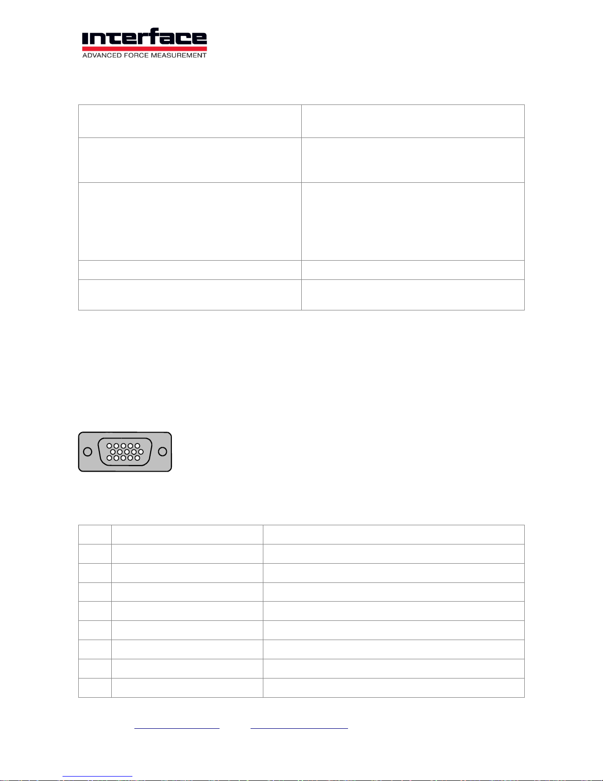
Pin Configuration
Input SUB-D15 HD
Connection of strain gauges, active sensors, TEDS. Activation of the bridge completion
with bridge from “HB” (12) to -UD (10).
No
Symbol
Description
1
TEDS
Transducer Electronic Data according to IEEE 1451.4
2
-Us
Negative Bridge Supply
3
+Us
Positive Bridge Supply
4
Q350
Quarter Bridge Completion 350 Ohm
5
+UD
Positive Differential Input
6
GNDE
Ground, Analog Input
7
-Uf
Negative Sense Line (6-wire connection only)
8
+Uf
Positive Sense Line (6-wire connection only)
1
5
11
15
Page 11
Interface Inc. ● 7401 East Butherus Drive, Scottsdale, Arizona 85260 USA ● Phone 480.948.5555 ● Fax 480.948.1924
Page 11 of 39
No
Symbol
Description
9
Q120
Quarter Bridge Completion 120 Ohm
10
-UD
Negative Differential Input
11
Q1k
Quarter Bridge Completion 1000 Ohm
12
HB
Half Bridge Completion
13
VCCIO
Supply Voltage for active sensors (optional)
14
Ue
Analog Input Voltage, single ended ±10V
15
GNDIO
Ground, Supply Voltage (optional)
Shield
PE
Earth (housing)
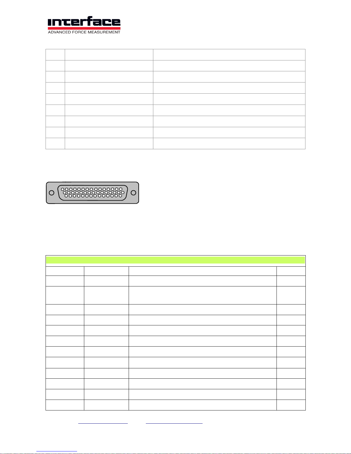
Input Sub-D44 HD
Up to 3 channels can be connected to the 44-pin Sub D socket. The labeling on the front
panel is 1/3 for connecting the channels 1 to 3.
1/3 Channel 1,2,3, Sub-D HD 44
Pin
Signal
Description
Channel
Shield
PE
Earth (housing)
-
1
TEDS
Transducer Electronic Data according IEEE
1451.4
1
2
US-
Negative Bridge Supply
1 3 US+
Positive Bridge Supply
1 4 Q350
Quarter Bridge Completion 350 Ohm
1 5 UD+
Positive Differential Input
1 6 GNDE
Ground, Analog Input
1
7
UF-
Negative Sense Line (6-wire connection only)
1
8
UF+
Positive Sense Line (6-wire connection only)
1 9 Q120
Quarter Bridge Completion 120Ohm
1
10
UD-
Negative Differential Input
1
11
Q1k
Quarter Bridge Completion 1000Ohm
1
1
15
31
44
Page 12
Interface Inc. ● 7401 East Butherus Drive, Scottsdale, Arizona 85260 USA ● Phone 480.948.5555 ● Fax 480.948.1924
Page 12 of 39
1/3 Channel 1,2,3, Sub-D HD 44
Pin
Signal
Description
Channel
12
HB
Half Bridge Completion
1
13
UE
Analog Input Voltage, single ended ±10V
1
14
GNDIO
Not equipped sep.galv. isol. (optional)
1
15
PE
Earth (housing)
-
16
TEDS
Transducer Electronic Data according IEEE
1451.4
2
17
US-
Negative Bridge Supply
2
18
US+
Positive Bridge Supply
2
19
Q350
Quarter Bridge Completion 350 Ohm
2
20
UD+
Positive Differential Input
2
21
GNDE
Ground, Analog Input
2
22
UF-
Negative Sense Line (6-wire connection only)
2
23
UF+
Positive Sense Line (6-wire connection only)
2
24
Q120
Quarter Bridge Completion 120 Ohm
2
25
UD-
Negative Differential Input
2
26
Q1k
Quarter Bridge Completion 1000 Ohm
2
27
HB
Half Bridge Completion
2
28
UE
Analog Input Voltage, single ended ±10V
2
29
GNDIO
not equipped sep.galv.isol. (optional)
2
30
VCCIO
not equipped sep.galv.isol. (optional)
1,2,3
31
TEDS
Transducer Electronic Data acc. to IEEE 1451.4
3
32
US-
Negative Bridge Supply
3
33
US+
Positive Bridge Supply
3
34
Q350
Quarter Bridge Completion 350 Ohm
3
35
UD+
Positive Differential Input
3
36
GNDE
Ground, Analog Input
3
37
UF-
Negative Sense Line (6-wire connection only)
3
38
UF+
Positive Sense Line (6-wire connection only)
3
39
Q120
Quarter Bridge Completion 120 Ohm
3
40
UD-
Negative Differential Input
3
41
Q1k
Quarter Bridge Completion 1000 Ohm
3
42
HB
Half Bridge Completion
3
Page 13
Interface Inc. ● 7401 East Butherus Drive, Scottsdale, Arizona 85260 USA ● Phone 480.948.5555 ● Fax 480.948.1924
Page 13 of 39
1/3 Channel 1,2,3, Sub-D HD 44
Pin
Signal
Description
Channel
43
UE
Analog Input Voltage, single ended ±10V
3
44
GNDIO
Not equipped sep.galv.isol. (optional)
3
The labelling on the front panel is 4/6 for connecting the channels 4 to 6.
4/6 Channel 4,5,6, Sub-D HD 44
Pin
Signal
Description
Channel
Shield
PE
Earth (housing)
- 1 TEDS
Transducer Electronic Data acc. to IEEE 1451.4
4 2 US-
Negative Bridge Supply
4 3 US+
Positive Bridge Supply
4 4 Q350
Quarter Bridge Completion 350 Ohm
4 5 UD+
Positive Differential Input
4 6 GNDE
Ground, Analog Input
4 7 UF-
Negative Sense Line (6-wire connection only)
4 8 UF+
Positive Sense Line (6-wire connection only)
4 9 Q120
Quarter Bridge Completion 120 Ohm
4
10
UD-
Negative Bridge Supply
4
11
Q1k
Quarter Bridge Completion 1000 Ohm
4
12
HB
Half Bridge Completion
4
13
UE
Analog Input Voltage, single ended ±10V
4
14
GNDIO
Not equipped sep.galv.isol. (optional)
4
15
PE
Earth (housing)
-
16
TEDS
Transducer Electronic Data acc. to IEEE 1451.4
5
17
US-
Negative Bridge Supply
5
18
US+
Positive Bridge Supply
5
19
Q350
Quarter Bridge Completion 350Ohm
5
20
UD+
Positive Differential Input
5
21
GNDE
Ground, Analog Input
5
22
UF-
Negative Sense Line (6-wire connection only)
5
23
UF+
Positive Sense Line (6-wire connection only)
5
24
Q120
Quarter Bridge Completion 120 Ohm
5
25
UD-
Negative Differential Input
5
26
Q1k
Quarter Bridge Completion 1000 Ohm
5
Page 14
Interface Inc. ● 7401 East Butherus Drive, Scottsdale, Arizona 85260 USA ● Phone 480.948.5555 ● Fax 480.948.1924
Page 14 of 39
4/6 Channel 4,5,6, Sub-D HD 44
Pin
Signal
Description
Channel
27
HB
Half Bridge Completion
5
28
UE
Analog Input Voltage, single ended ±10V
5
29
GNDIO
not equipped sep.galv.isol. (optional)
5
30
VCCIO
not equipped sep.galv.isol. (optional)
4,5,6
31
TEDS
Transducer Electronic Data acc. to IEEE 1451.4
6
32
US-
Negative Bridge Supply
6
33
US+
Positive Bridge Supply
6
34
Q350
Quarter Bridge Completion 350 Ohm
6
35
UD+
Positive Differential Input
6
36
GNDE
Ground, Analog Input
6
37
UF-
Negative Sense Line (6-wire connection only)
6
38
UF+
Positive Sense Line (6-wire connection only)
6
39
Q120
Quarter Bridge Completion 120 Ohm
6
40
UD-
Negative Differential Input
6
41
Q1k
Quarter Bridge Completion 1000 Ohm
6
42
HB
Half Bridge Completion
6
43
UE
Analog Input Voltage, single ended ±10V
6
44
GNDIO
Not equipped sep.galv.isol. (optional)
6
At the 44-pole SubD socket 1/6 up to 6 channels can be connected. The labeling on the
front panel is 1/6 for connecting the channels 1 to 6 The connections are parallel to the
input jacks 1/3 and 4/6 .
Channel 1,2,3,4,5,6, Sub-D HD 44
Pin
Signal
Description
Channel
Shield
PE
Earth (housing)
- 1 UF+
Positive Sense Line (6-wire connection only)
1 2 US+
Positive Bridge Supply
1 3 UD+
Positive Differential Input
1 4 UD-
Negative Differential Input
1 5 US-
Negative Bridge Supply
1 6 UF-
Negative Sense Line (6-wire connection only)
1 7 TEDS
Transducer Electronic Data according IEEE 1451.4
1
8
UF+
Positive Sense Line (6-wire connection only)
2
9
US+
Positive Bridge Supply
2
Page 15
Interface Inc. ● 7401 East Butherus Drive, Scottsdale, Arizona 85260 USA ● Phone 480.948.5555 ● Fax 480.948.1924
Page 15 of 39
Channel 1,2,3,4,5,6, Sub-D HD 44
Pin
Signal
Description
Channel
10
UD+
Positive Differential Input
2
11
UD-
Negative Differential Input
2
12
US-
Negative Bridge Supply
2
13
UF-
Negative Sense Line (6-wire connection only)
2
14
TEDS
Transducer Electronic Data according IEEE 1451.4
2
15
PE
Earth (housing)
-
16
UF+
Positive Sense Line (6-wire connection only)
3
17
US+
Positive Bridge Supply
3
18
UD+
Positive Differential Input
3
19
UD-
Negative Differential Input
3
20
US-
Negative Bridge Supply
3
21
UF-
Negative Sense Line (6-wire connection only)
3
22
TEDS
Transducer Electronic Data according IEEE 1451.4
3
23
UF+
Positive Sense Line (6-wire connection only)
4
24
US+
Positive Bridge Supply
4
25
UD+
Positive Differential Input
4
26
UD-
Negative Differential Input
4
27
US-
Negative Bridge Supply
4
28
UF-
Negative Sense Line (6-wire connection only)
4
29
TEDS
Transducer Electronic Data acc. to IEEE 1451.4
4
30
PE
Earth (housing)
-
31
UF+
Positive Sense Line (6-wire connection only)
5
32
US+
Positive Bridge Supply
5
33
UD+
Positive Differential Input
5
34
UD-
Negative Differential Input
5
35
US-
Negative Bridge Supply
5
36
UF-
Negative Sense Line (6-wire connection only)
5
37
TEDS
Transducer Electronic Data according IEEE 1451.4
5
38
UF+
Positive Sense Line (6-wire connection only)
6
39
US+
Positive Bridge Supply
6
40
UD+
Positive Differential Input
6
41
UD-
Negative Differential Input
6
Page 16
Interface Inc. ● 7401 East Butherus Drive, Scottsdale, Arizona 85260 USA ● Phone 480.948.5555 ● Fax 480.948.1924
Page 16 of 39
Channel 1,2,3,4,5,6, Sub-D HD 44
Pin
Signal
Description
Channel
42
US-
Negative Bridge Supply
6
43
UF-
Negative Sense Line (6-wire connection only)
6
44
TEDS
Transducer Electronic Data acc. to IEEE 1451.4
6
At the 44-pin Sub D socket 7/8 up to 2 channels can be connected (channel 7 and channel
8) .
Channel 7, 8, Sub-D HD 44
Pin
Signal
Description
Channel
Shield
PE
Earth (housing)
- 1 UE
Analog Input Voltage, single ended ±10V
1 2 GNDE
Ground, Analog Input
1 3 UE
Analog Input Voltage, single ended ±10V
2 4 GNDE
Ground, Analog input
2 5 UE
Analog Input Voltage, single ended ±10V
3 6 GNDE
Ground, Analog Input
3 7 UE
Analog input voltage, single ended ±10V
4
8
GNDE
Ground, Analog input
4
9
UE
Analog Input Voltage, single ended ±10V
5
10
GNDE
Ground, Analog Input
5
11
UE
Analog Input Voltage, single ended ±10V
6
12
GNDE
Ground, Analog Input
6
13
PE
Earth (housing)
-
14
PE
Earth (housing)
-
15
PE
Earth (housing)
-
16
TEDS
Transducer Electronic Data according IEEE 1451.4
7
17
US-
Negative Bridge Supply
7
18
US+
Positive Bridge Supply
7
19
Q350
Quarter Bridge Completion 350 Ohm
7
20
UD+
Positive Differential Input
7
21
GNDE
Ground, Analog Input
7
22
UF-
Negative Sense Line (6-wire connection only)
7
23
UF+
Positive Sense Line (6-wire connection only)
7
24
Q120
Quarter Bridge Completion 120Ohm
7
25
UD-
Negative Differential Input
7
Page 17
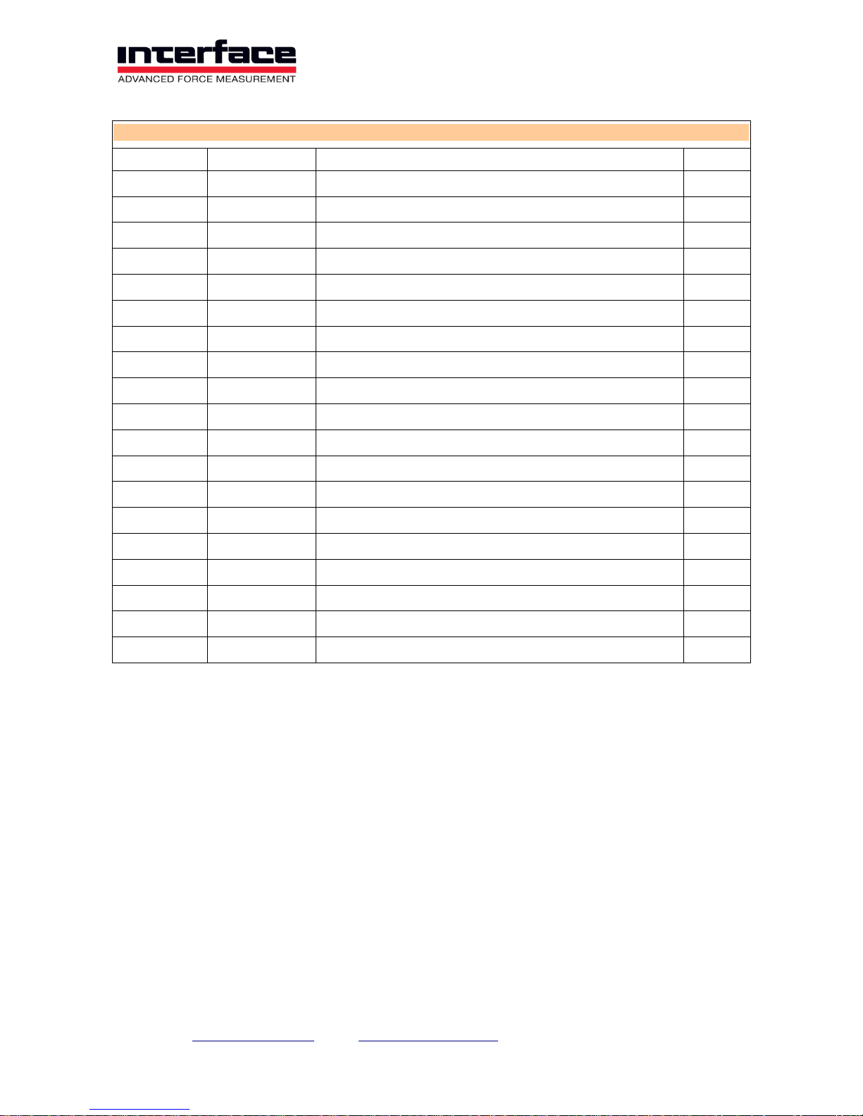
Interface Inc. ● 7401 East Butherus Drive, Scottsdale, Arizona 85260 USA ● Phone 480.948.5555 ● Fax 480.948.1924
Page 17 of 39
Channel 7, 8, Sub-D HD 44
Pin
Signal
Description
Channel
26
Q1k
Quarter Bridge Completion 1000Ohm
7
27
HB
Half Bridge Completion
7
28
UE
Analog Input Voltage, single ended ±10V
7
29
GNDIO
not equipped sep.galv.isol. (optional)
7
30
VCCIO
not equipped sep.galv.isol. (optional)
7,8
31
TEDS
Transducer Electronic Data according IEEE 1451.4
8
32
US-
Negative Bridge Supply
8
33
US+
Positive Bridge Supply
8
34
Q350
Quarter Bridge Completion 350 Ohm
8
35
UD+
Positive Differential Input
8
36
GNDE
Ground, Analog Input
8
37
UF-
Negative Sense Line (6-wire connection only)
8
38
UF+
Positive Sense Line (6-wire connection only)
8
39
Q120
Quarter Bridge Completion 120Ohm
8
40
UD-
Negative Differential Input
8
41
Q1k
Quarter Bridge Completion 1000Ohm
8
42
HB
Half Bridge Completion
8
43
UE
Analog Input Voltage, single ended ±10V
8
44
GNDIO
not equipped sep.galv.isol. (optional)
8
Page 18
Interface Inc. ● 7401 East Butherus Drive, Scottsdale, Arizona 85260 USA ● Phone 480.948.5555 ● Fax 480.948.1924
Page 18 of 39
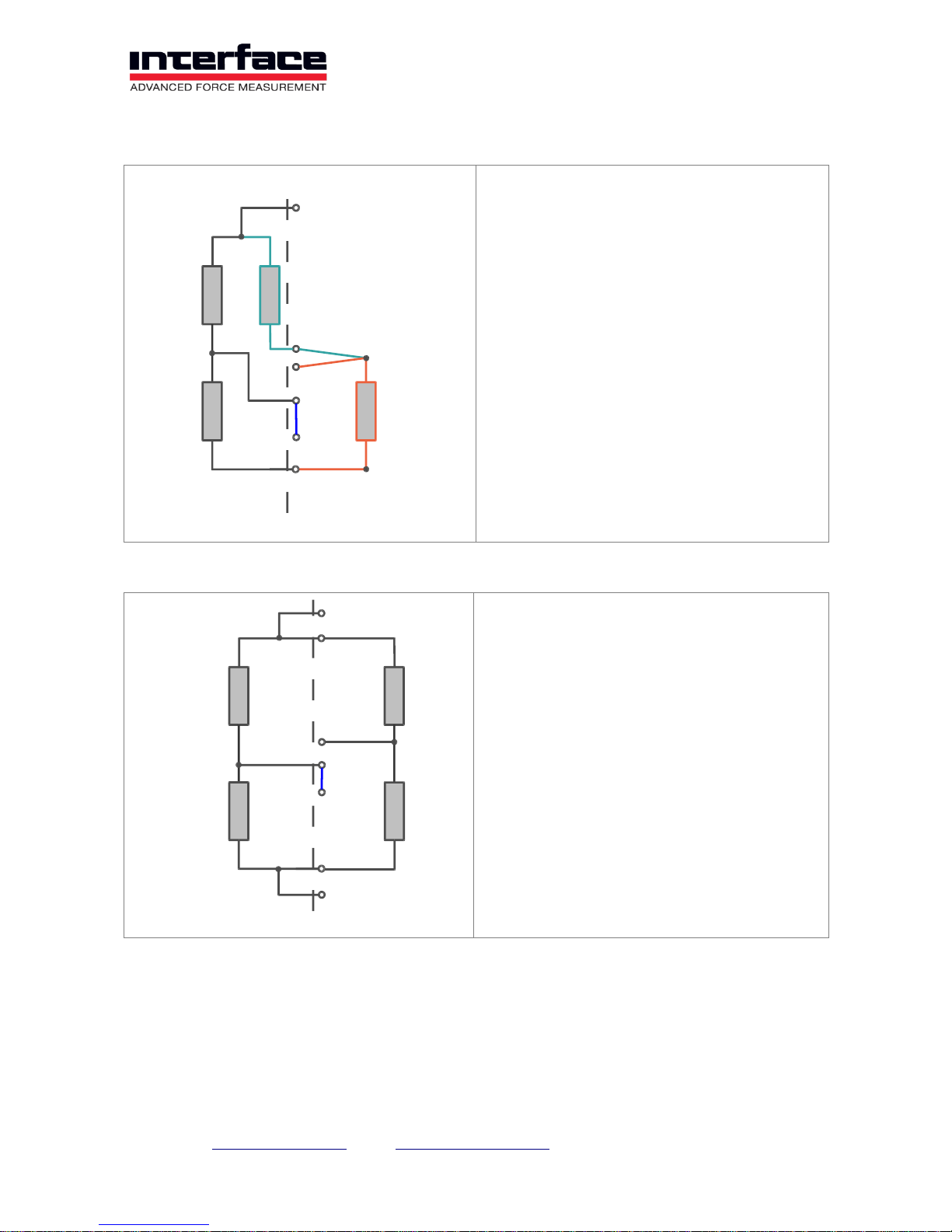
Connection strain gage quarter bridge
The active strain gage R3 is connected in
the 3-wire technology.
The completion resistors 120 Ohm (QB =
Q120), 350 Ohm (QB = Q350) and 1K Ohm
(QB = Q1k) are lead out on the connection
QB.
The internal half bridge R1, R2 is activated
with a bridge from HB to -Ud.
Connection strain gage half bridge
The active strain gages R3 and R4 are
connected on +Us, +Ud and -Us.
For very long wire lengths the sensor cable
+Uf and -Uf can be used.
The internal half bridge R1, R2 is activated
with a bridge HB to -Ud.
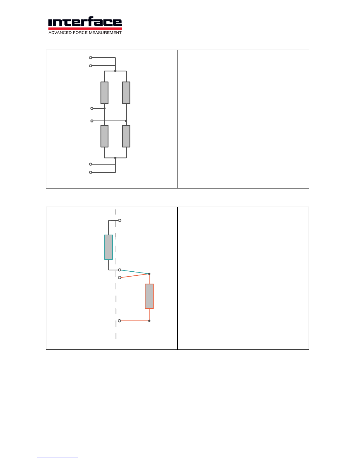
Connection strain gage full bridge
+Us
R1
R2
R4
R3
+Ud
-Ud
-Us
QB
HB
+Us
R1
R2
R4
R3
+Ud
-Ud
-Us
HB
+Uf
+Uf
Page 19
Interface Inc. ● 7401 East Butherus Drive, Scottsdale, Arizona 85260 USA ● Phone 480.948.5555 ● Fax 480.948.1924
Page 19 of 39
The active strain gages R1 to R4 are
connected on +Us, -Us, +Ud, -Ud.
For very long wire lengths the sensor cable
+Uf and -Uf can be additionally used.
Connection of PT1000
The temperature sensor PT1000 is
connected in three-wire technology to the
terminals Q1K, UE and GNDE.
To measure temperature, the input type
"PT1000" must be activated once by
software.
Connection of the active sensors
The voltage signal of active sensors is applied to Ue and GNDE.
Potentiometric sensors can be supplied via +Us. The power supply for active sensors can
be via galvanic isolated voltage VCCIO and GNDIO.
+Us
R1
R2
R4
R3
-Ud
+Ud
-Us
-Uf
+Uf
Us+
1 KOhm
PT1000
UE
GNDE
Q1K
Page 20
Interface Inc. ● 7401 East Butherus Drive, Scottsdale, Arizona 85260 USA ● Phone 480.948.5555 ● Fax 480.948.1924
Page 20 of 39
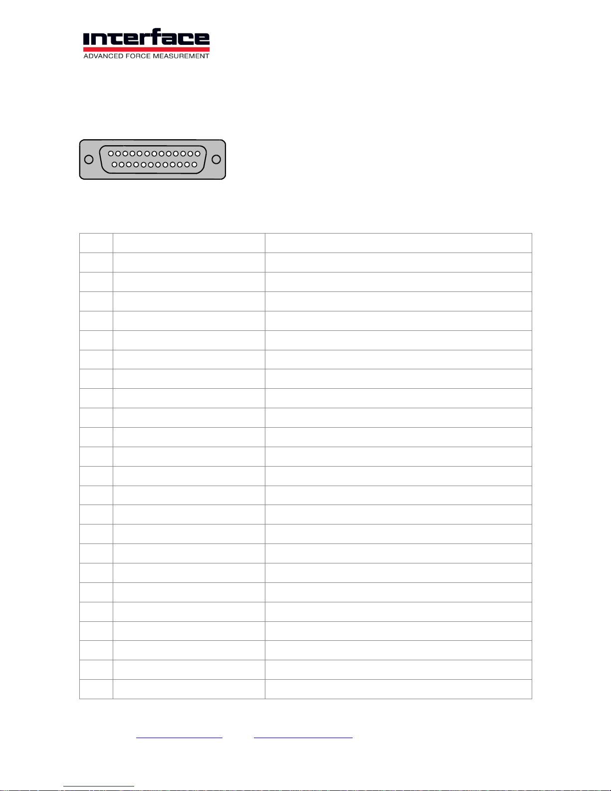
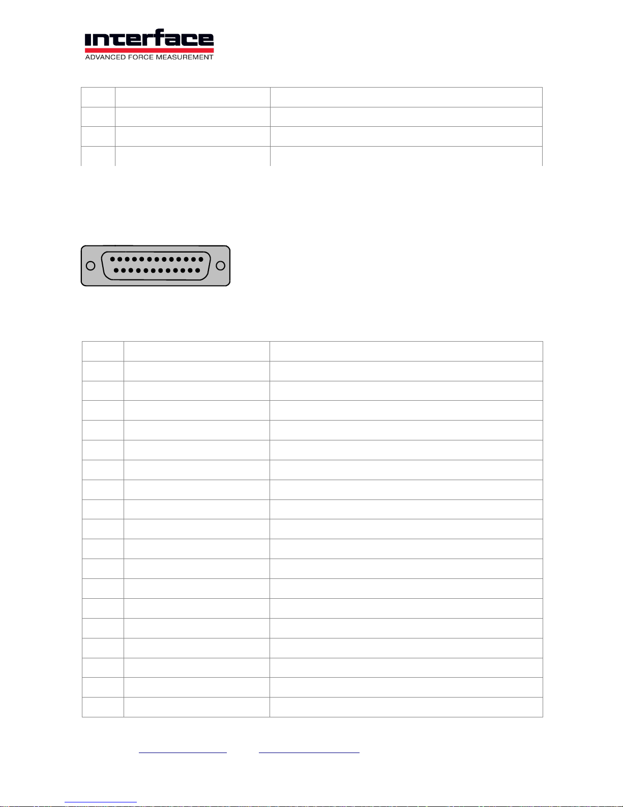
Analog Output SUB-D25 socket
Analog outputs voltage or current for channels 1 to 8.
Pin
Signal
Meaning
1
Ua1/ Ia1
Analog Out Channel 1
2
GNDA
Analog GND
3
Ua2/ Ia2
Analog Out Channel 2
4
GNDA
Analog GND
5
Ua3/ Ia3
Analog Out Channel 3
6
GNDA
Analog GND
7
Ua4/ Ia4
Analog Out Channel 4
8
GNDA
Analog GND
9
Ua5/ Ia5
Analog Out Channel 5
10
GNDA
Analog GND
11
Ua6/ Ia6
Analog Out Channel 6
12
GNDA
Analog GND
13
Ua7/ Ia7
Analog Out Channel 7
14
GNDA
Analog GND
15
Ua8/ Ia8
Analog Out Channel 8
16
GNDA
Analog GND
17 / Internal usage
18 / Internal sage
19 / Internal usage
20 / Internal usage
21
GNDINT
GNDINT
22
GNDINT
GNDINT
23
OutB-
60kHz frequency -6V Out
1
13
14
25
Page 21
Interface Inc. ● 7401 East Butherus Drive, Scottsdale, Arizona 85260 USA ● Phone 480.948.5555 ● Fax 480.948.1924
Page 21 of 39
Pin
Signal
Meaning
24
OutB+
60kHz frequency +6V Out
25
GNDINT
GNDINT
Shield
PE
Earth (housing)
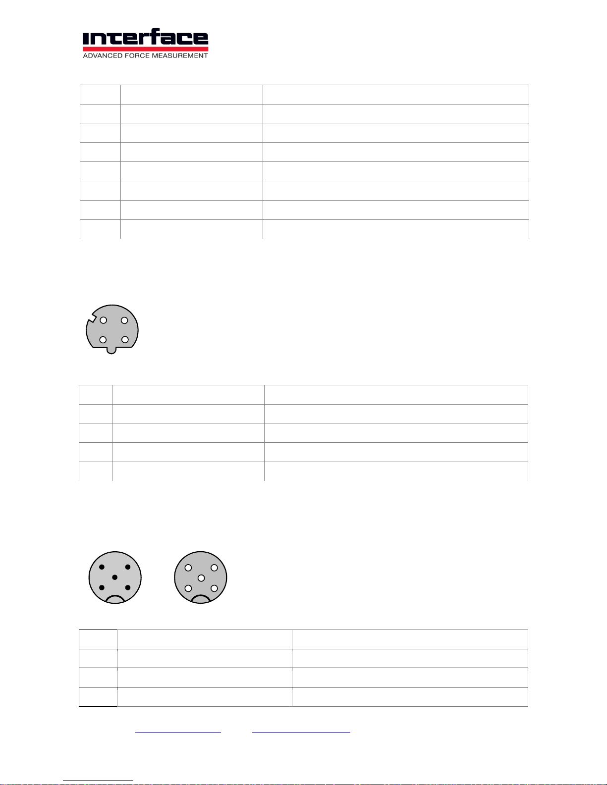
Digital in- and outputs Sub-D25 plug connector
Pin
Name
Meaning
1
VCC
5V Voltage Supply, digital
2
DGND
Digital Ground (GND)
3
DGND
Digital Ground (GND)
4
DGND
Digital Ground (GND)
5
DGND
Digital Ground (GND)
6
DIO 2
Group 1, 1.2
7
DIO 4
Group 1, 1.4
8
DIO 6
Group 2, 2.2
9
DIO 8
Group 2, 2.4
10
DIO 10
Group 3, 3.2
11
DIO 12
Group 3, 3.4
12
DIO 14
Group 4, 4.2
13
DIO 16
Group 4, 4.4
14
DGND
Digital Ground (GND)
15
DGND
Digital Ground (GND)
16
DGND
Digital Ground (GND)
17
DGND
Digital Ground (GND)
18
DIO 1
Group 1, 1.1
13
1
25
14
Page 22
Interface Inc. ● 7401 East Butherus Drive, Scottsdale, Arizona 85260 USA ● Phone 480.948.5555 ● Fax 480.948.1924
Page 22 of 39
Pin
Name
Meaning
19
DIO 3
Group 1, 1.3
20
DIO 5
Group 2, 2.1
21
DIO 7
Group 2, 2.3
22
DIO 9
Group 3, 3.1
23
DIO 11
Group 3, 3.3
24
DIO 13
Group 4, 4.1
25
DIO 15
Group 4, 4.3
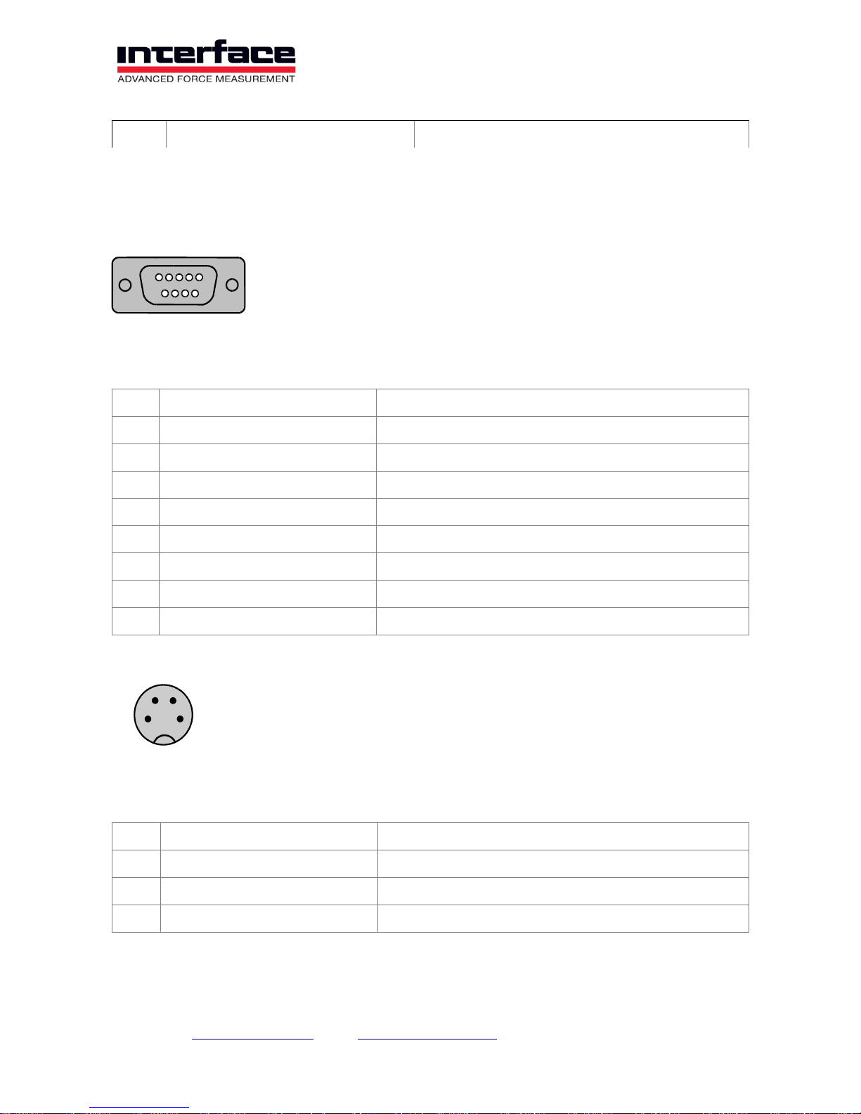
EtherCat M12 4-pole socket D-coded
1
TD+
Transmit +
2
RD+
Receive +
3
TD-
Transmit -
4
RD-
Receive -
Shield
PE
Earth (housing)
CANbus M12 5-pole socket / plug A-coded
1
Shield
Shielding
2
V+
Power (UB+)
3
V-
GND (UB-)
4
CAN_H
Dominant High
1
2
3
4
1
2
4 3
5
2
3
4
5
1
Page 23
Interface Inc. ● 7401 East Butherus Drive, Scottsdale, Arizona 85260 USA ● Phone 480.948.5555 ● Fax 480.948.1924
Page 23 of 39
5
CAN_L
Dominant Low
UART Port Sub-D9 socket
The UART Port is used for connection of Raspberry PI.
1
UB-
Ground Supply Voltage
2
RX
Receive Data of BX8, 3.3Volt level
3
TX
Transmit Data of BX8, 3.3 Volt level
4 / Internal Usage
5
UB-
Ground Supply Voltage
6
UB+
Supply Voltage
7 / Internal
8
UB+
Supply Voltage
9
OFF
Disable
Voltage supply M8, 4-pole
1
UB+
Positive Operating Voltage 10-27V, brown
2
PE
Housing PE, white
3
UB-
Negative Operating Voltage (GND), blue
4
PE
Housing PE, black
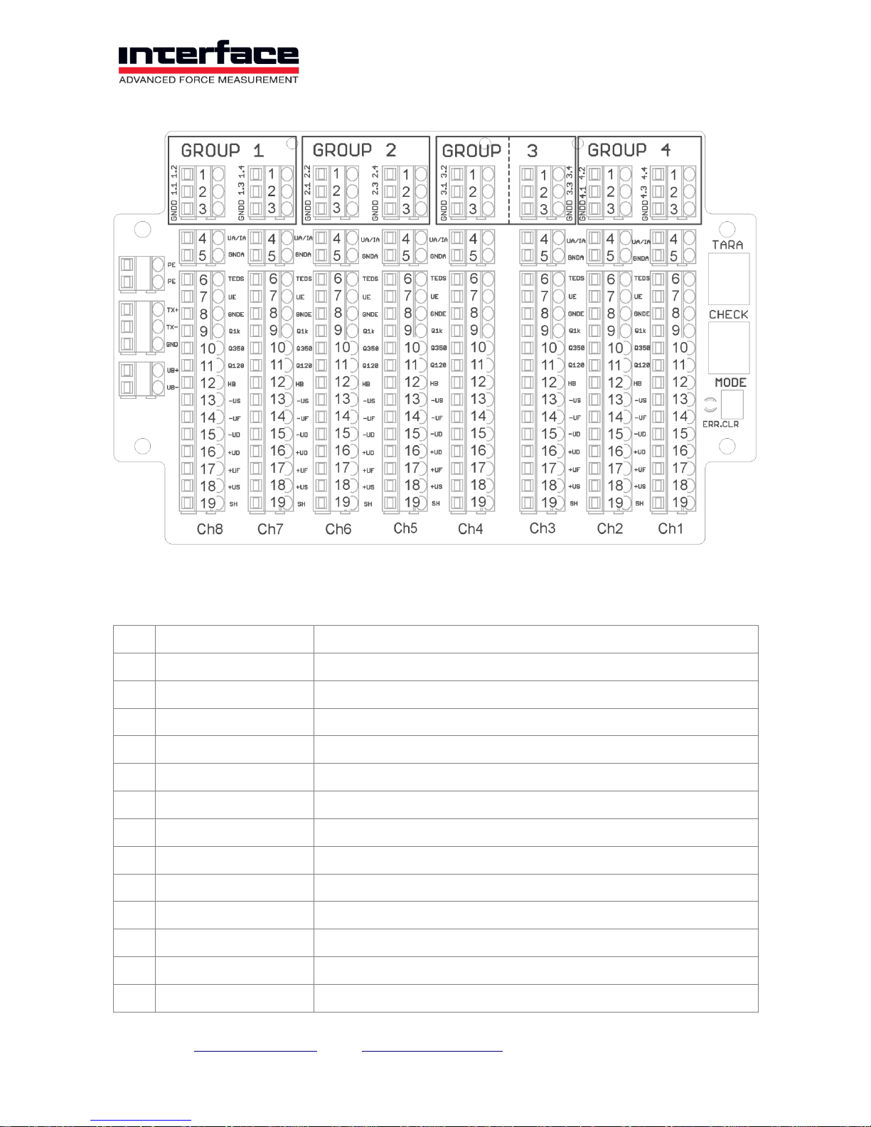
Screw terminal BX8-AS
1
2
4
3
1
5
6
9
Page 24
Interface Inc. ● 7401 East Butherus Drive, Scottsdale, Arizona 85260 USA ● Phone 480.948.5555 ● Fax 480.948.1924
Page 24 of 39
Pos.
Terminal labelling
Description
1
n.2 / n.4 Group n
Digital In/Out Nr. 2 / 4 / 6 / 8 / 10 / 12 / 14 / 16
2
n.1 / n.3 Group n
Digital In/Out Nr. 1 / 3 / 5 / 7 / 9 / 11 / 13 / 15
3
GNDD
Earth, Digital In/Out
4
UA/IA
Analog Output, current or voltage
5
GNDA
Ground, Analog output
6
TEDS
Transducer Electronic Data according to IEEE 1451.4
7
UE
Voltage, Analog Input, single ended +/-10V
8
GNDE
Ground, Analog Input
9
Q1k
Quarter Bridge Completion 1000 Ohm
10
Q350
Quarter Bridge Completion 350 Ohm
11
Q120
Quarter Bridge Completion 120 Ohm
12
HB
Half Bridge Completion
13
-US
Negative Bridge Supply
Page 25
Interface Inc. ● 7401 East Butherus Drive, Scottsdale, Arizona 85260 USA ● Phone 480.948.5555 ● Fax 480.948.1924
Page 25 of 39
14
-UF
Negative Excitation Sense (6-wire connection only)
15
-UD
Negative Differential Input
16
+UD
Positive Differential Input
17
+UF
Positive Excitation Sense (6-wire connection only)
18
+US
Positive Bridge Supply
19
SH
Earth, Analog input (shielding)
Page 26
Interface Inc. ● 7401 East Butherus Drive, Scottsdale, Arizona 85260 USA ● Phone 480.948.5555 ● Fax 480.948.1924
Page 26 of 39
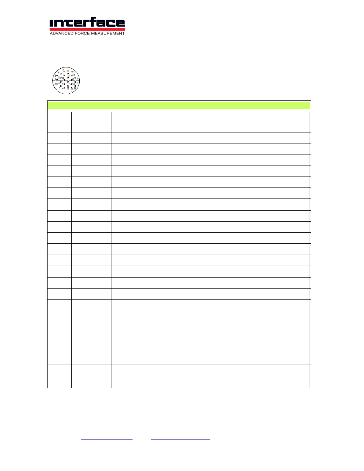
24-Pin M16 Connector BX8-AS
1/6 Channel 1,2,3,4,5,6
Pin
Symbol
Description
Channel
1
US+
Positive Bridge Excitation
1
2 US-
Negative Bridge Excitation
1
3 UD+
Positive Bridge Output
1
4 UD-
Negative Bridge Output
1
5 US+
Positive Bridge Excitation
2
6 US-
Negative Bridge Excitation
2
7 UD+
Positive Bridge Output
2
8
UD-
Negative Bridge Output
2
9
US+
Positive Bridge Excitation
3
10
US-
Negative Bridge Excitation
3
11
UD+
Positive Bridge Output
3
12
UD-
Negative Bridge Output
3
13
US+
Positive Bridge Excitation
4
14
US-
Negative Bridge Excitation
4
15
UD+
Positive Bridge Output
4
16
UD-
Negative Bridge Output
4
17
US+
Positive Bridge Excitation
5
18
US-
Negative Bridge Excitation
5
19
UD+
Positive Bridge Output
5
20
UD-
Negative Bridge Output
5
21
US+
Positive Bridge Excitation
6
22
US-
Negative Bridge Excitation
6
23
UD+
Positive Bridge Output
6
24
UD-
Negative Bridge Output
6
Page 27
Interface Inc. ● 7401 East Butherus Drive, Scottsdale, Arizona 85260 USA ● Phone 480.948.5555 ● Fax 480.948.1924
Page 27 of 39
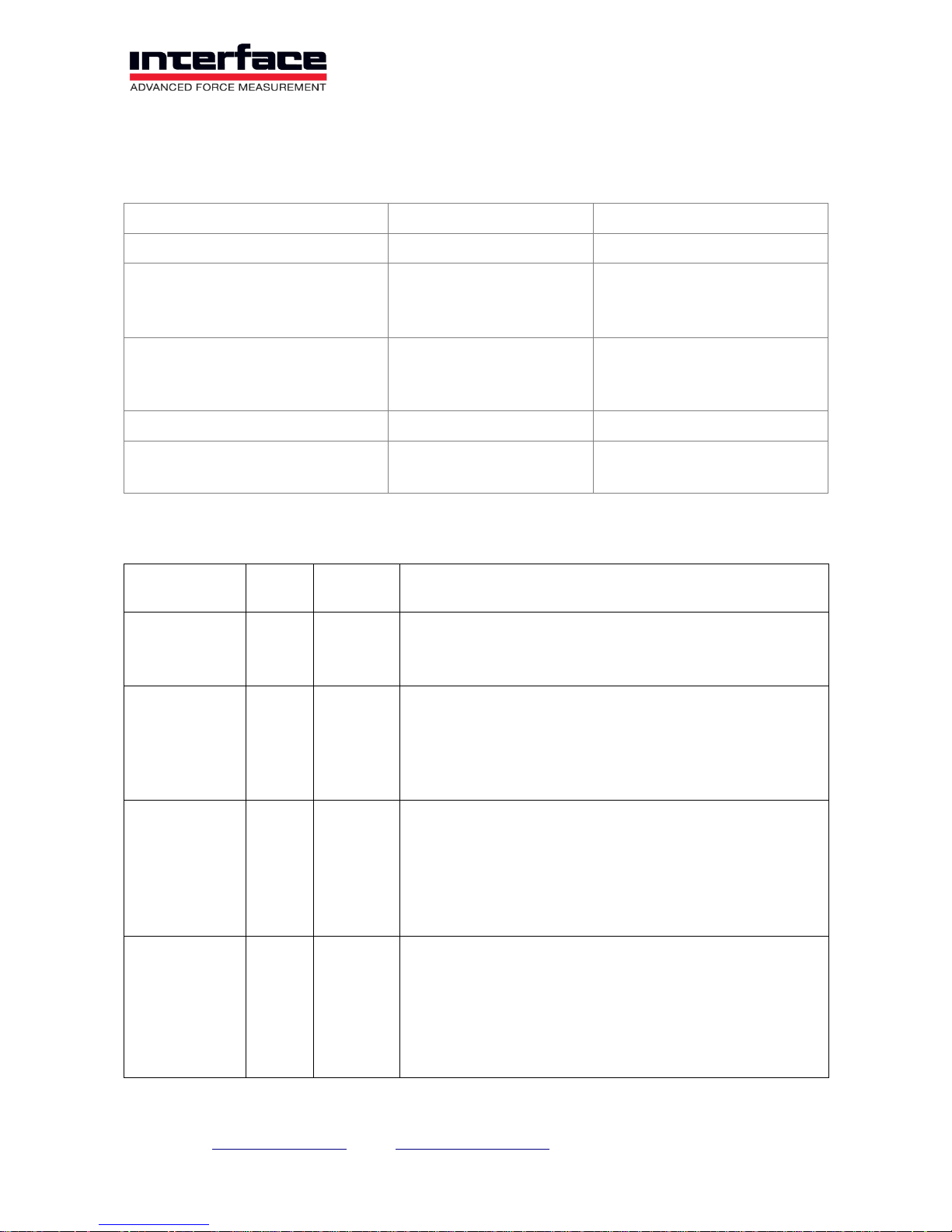
Annex
LED-display for status
Device state
FUNCTION-LED
EC-RUN-LED
EtherCAT State=INIT (not active)
Permanently on
Off
EtherCAT State=PREOP
Off
Blinking
200ms on
200ms off
EtherCAT State= SAFEOP
Off
Single flash
200ms on,
1s off
EtherCAT State= OP
Off
Permanently on
USB-Bootloader active (EtherCAT
not used)
300ms on
300ms off
Off
LED-display for error condition
Error
condition
Priority
STATUS
LED
Meaning
EtherCAT:
State-transition
inhibited
1
Blinking
200ms on
200ms off
Requested status transition impossible, e.g. because
of invalid settings or invalid hardware settings
EtherCAT:
State
automatically
reset
1
Single
flash
200ms on,
1s off
Device switched from operating state to SafeOpError
because of a synchronization error
EtherCAT:
Application
watchdog
timeout
1
Double
flash
200ms on,
200ms off
200ms on
1sec off
If Watchdog-timer is active: process data frame not
received within watchdog time
Measuring
application:
Sensor error
2
Permanent
on
1. A sensor or its cable is defective, for example, the cable
Ud+ or Ud- could be interrupted or could have short
circuited with one of the cables Us+ or Us-. 2. A measured
value is saturated, i.e. the measuring signal lies outside of
the measuring range. This could be ascribed to a defective
sensor. 3. The maximum value is exceeded for a six-axis
sensor.
Page 28
Interface Inc. ● 7401 East Butherus Drive, Scottsdale, Arizona 85260 USA ● Phone 480.948.5555 ● Fax 480.948.1924
Page 28 of 39
Error
condition
Priority
STATUS
LED
Meaning
Measuring
application:
Error at the
digital output
3
Blinks
slowly
500ms on
500ms off
Short-circuit at the digital output, i.e. if this is connected as
an output and switched to High, it has short-circuited with
GNDD, or if it is switched to Low, a voltage >=3 V is
applied.
Measuring
application:
Error at the
analog output
4
Blinks very
slowly
1s on
1s off
Open current output or overheating of the output driver, for
example as a result of a short-circuited voltage output.
Bootloader:
Firmwareupdate failed
1
Permanent
on
Checksum error after writing to flash memory during
firmware update
FUNCTION LED
The FUNCTION LED lights up permanently in yellow (Blue for BX8-HD15 and BX8-HD44)
during normal operation. This blinks after activating the firmware update function (see
Annex A).
STATUS LED (red)
The STATUS LED indicates errors that have occurred:
If it lights up permanently in red, an error at the sensor input has occurred. This can be
caused by three things:
A sensor or its cable is defective, for example, the cable Ud+ or Ud- could be
interrupted or short circuited with one of the cables Us+ or Us-.
A measured value is saturated, i.e. the measuring signal lies outside the
measuring range. This could be from a damaged or defective sensor.
The maximum value is exceeded for a six-axis sensor.
If the STATUS LED blinks slowly (approx. 1x/s), an error has occurred at the analog
output. This could be an open current output or overheating of the output driver, for
example, as a result of a short-circuited output voltage.
If the STATUS LED blinks quickly (approx. 2x/sec), an error has occurred at the digital
output, namely a short circuit, i.e. if this is connected as an output and switched to High, it
has short-circuited with GNDD, or if it is switched to Low, a voltage >=3 V is connected.
Page 29

Interface Inc. ● 7401 East Butherus Drive, Scottsdale, Arizona 85260 USA ● Phone 480.948.5555 ● Fax 480.948.1924
Page 29 of 39
The status display of the error can be cleared by pressing the MODE button (located in the
housing) if the error is currently no longer present.
Detailed error information is stored in the device and can be accessed by the factory
terminal program.
Page 30
Interface Inc. ● 7401 East Butherus Drive, Scottsdale, Arizona 85260 USA ● Phone 480.948.5555 ● Fax 480.948.1924
Page 30 of 39
Digital inputs and outputs
The BX8 has 16 configurable 5V TTL compatible digital inputs and outputs (‘DIOs’). These
are organized into 4 groups which are identified on the terminal connections as ‘Group 1’
to ‘Group 4’. The respective DIOs are identified here as <GroupNo.>.<DIOno>.
The DIOs can be configured as an input or output function, whereby the DIOs within one
group must all have the same data direction.
Digital-I/O Numbers
In the devices and windows API (DLL), the numbers of the DIOs are assigned to the
terminal connection identification as follows:
Number in the API
and terminal program
Belongs to group
Identification on the terminal board
1 1 1.1 2 1
1.2 3 1
1.3 4 1
1.4 5 2
2.1 6 2
2.2 7 2
2.3 8 2
2.4 9 3
3.1
10 3 3.2
11 3 3.3
12 3 3.4
13 4 4.1
14 4 4.2
15 4 4.3
16 4 4.4
Page 31
Interface Inc. ● 7401 East Butherus Drive, Scottsdale, Arizona 85260 USA ● Phone 480.948.5555 ● Fax 480.948.1924
Page 31 of 39
Digital I/O Functions
The following functions can be configured:
No
Function
Data
direction
Device
command
Short description
1
GeneralPurpose Input
Input
0x000004
General input.
2
Zero setting
single channel
Input
0x000010
The active input level sets an Analog input
channel to zero.
3
Zero setting
all channels
Input
0x000020
The active input level sets all Analog input
channels to zero.
4
Resetting the
maximum and
minimum
value
determination
Input
0x000040
The active input level resets all maximum and
minimum values.
5
Trigger send
actual value
Input
0x000080
Triggers the sending of a measured value frame
with actual measured values via a USB
interface to the inactive-to-active edge of the
digital input.
6
Trigger
maximum
value
Input
0x000100
The maximum value determination is started for
the inactive-to-active edge at the digital input
(all input channels) and a frame with these
maximum values is sent to the USB interface at
the active-to-inactive edge.
7
Trigger
minimum
value
Input
0x000200
The minimum value determination is started for
the inactive-to-active edge at the digital input
(all input channels) and a frame with these
minimum values is sent to the USB interface at
the active-to-inactive edge.
8
Trigger mean
value
Input
0x000400
A decimating mean value formation is started
for the inactive-to-active edge on the digital
input (all input channels) and a frame with these
mean values is sent to the USB interface at the
active-to-inactive edge.
9
Trigger send
actual value
Input
0x000800
While the input level is active, measured value
frames with actual measured values are sent
via a USB interface at the set data rate.
10
General
purpose
output
Output
0x001000
General output.
Page 32
Interface Inc. ● 7401 East Butherus Drive, Scottsdale, Arizona 85260 USA ● Phone 480.948.5555 ● Fax 480.948.1924
Page 32 of 39
11
Threshold
output actual
measured
values
Output
0x010000
Threshold value output: The output is activated
if the assigned measured value is larger than
the upper threshold value and is deactivated if it
is smaller than the lower threshold value.
12
Threshold
output
Maximum
value
Output
0x014000
Threshold value output: The output is activated
if the assigned maximum value is larger than
the upper threshold value and is deactivated if it
is smaller than the lower threshold value.
13
Threshold
output
minimum
value
Output
0x018000
Threshold value output: The output is activated
if the assigned minimum value is larger than the
upper threshold value and is deactivated if it is
smaller than the lower threshold value.
14
Window
comparator
output actual
measured
value
Output
0x012000
Window comparator: The output is activated if
the assigned measured value is smaller than
the upper threshold value and larger than the
lower threshold value; otherwise it is
deactivated.
15
Window
comparator
output
maximum
value
Output
0x016000
Window comparator: The output is activated if
the assigned maximum value is smaller than the
upper threshold value and larger than the lower
threshold value; otherwise it is deactivated.
16
Window
comparator
output
minimum
value
Output
0x01A000
Window comparator: The output is activated if
the assigned minimum value is smaller than the
upper threshold value and larger than the lower
threshold value; otherwise it is deactivated.
Digital Inputs, Inversion
The DIOs have pull-up resistances that generate high levels when the input is open. For
input trigger functions that are intended to be used with a switch or button, that one must
be connected between the DIO and the GNDD terminal. The line must be functionally
inverted by software so that the function can be executed when the switch is closed. When
using the device interfaces or DLL, the specified value in the above mentioned column
‘Value’ must be ORed with 0x80000 for this purpose.
The threshold value outputs can also be inverted in this way.
The terms in the above mentioned table mean:
Level
Non-inverted
Inverted
Active
Logic 1 = High = 5V
Logic 0 = Low = 0V
Inactive
Logic 0 = Low = 0V
Logic 1 = High = 5V
Only when using the general purpose functions (no. 1 and 10 in the above table) does the
inversion have no effect.
Page 33

Interface Inc. ● 7401 East Butherus Drive, Scottsdale, Arizona 85260 USA ● Phone 480.948.5555 ● Fax 480.948.1924
Page 33 of 39
Other Notes Digital I/O
The default level can be defined for digital outputs, i.e. the level that the output should take
after restarting and after a reconfiguration. This setting also applies directly, i.e.
independent of the inversion state.
The general constant data transmission should be turned off for measured value-sendtrigger functions (no. 5 to 9 in the above-mentioned table). This can be done with the
button “y” in the terminal program.
Page 34
Interface Inc. ● 7401 East Butherus Drive, Scottsdale, Arizona 85260 USA ● Phone 480.948.5555 ● Fax 480.948.1924
Page 34 of 39
Measured data acquisition
The BX8 has a 24-bit sigma delta AD converter that records all 8 channels simultaneously
(simultaneous sampling). It is set to a fixed single sampling rate of 48000 samples/second
(total sampling rate = 48000/s x 8 channels = 384000/s). These are decimated down by a
digital anti-aliasing filter to fixed values depending on the selected data rate, whereby all
input samples are included in the calculation (output decimation). The cut-off frequencies
mentioned in the following table arise due to this input filter, i.e. these apply if:
- The analog input filter is set to the highest value of 11.4 kHz and
- The switchable digital filters (see above) are switched off.
Data rate in frames/s
Decimation divisor
-3 dB cutoff frequency in Hz
1
48000
0.4 2 24000
0.8 3 16000
1.2 4 12000
1.6 5 9600
2
6
8000
2.4 8 6000
3.2
10
4800
4
12
4000
4.8
15
3200
6
16
3000
6.4
20
2400
8
24
2000
9.,6
25
1920
10
30
1600
12
32
1500
12.8
40
1200
16
48
1000
19.2
50
960
20
60
800
24
75
640
30
80
600
32
96
500
38.4
100
480
40
Page 35
Interface Inc. ● 7401 East Butherus Drive, Scottsdale, Arizona 85260 USA ● Phone 480.948.5555 ● Fax 480.948.1924
Page 35 of 39
Data rate in frames/s
Decimation divisor
-3 dB cutoff frequency in Hz
120
400
48
125
384
50
150
320
60
160
300
64
192
250
76.8
200
240
80
240
200
96
250
192
100
300
160
120
320
150
128
375
128
150
384
125
153.6
400
120
160
480
100
192
500
96
200
600
80
240
640
75
256
750
64
300
800
60
320
960
50
384
1000
48
400
1200
40
480
1500
32
600
1600
30
640
1920
25
768
2000
24
800
2400
20
960
3000
16
1200
3200
15
1280
4000
12
1600
4800
10
1920
Page 36
Interface Inc. ● 7401 East Butherus Drive, Scottsdale, Arizona 85260 USA ● Phone 480.948.5555 ● Fax 480.948.1924
Page 36 of 39
Data rate in frames/s
Decimation divisor
-3 dB cutoff frequency in Hz
6000
8
2400
8000
6
3200
9600
5
3840
12000
4
4800
16000
3
6400
24000
2
9600
48000
1
11400
Note: The configurable maximum data frequency depends on other settings of the device.
When setting the data frequency, the BX8 checks if the desired data frequency is possible
and refuses the command, if not. The maximum configurable data frequency can be
determined by a read command. Examples of settings that have an impact on the
maximum data frequency are:
- Measured data type
- Bit rate of the UART interface, if activated (if present)
- Digital FIR- and IIR-filters
- Trigger- and threshold functions of the digital I/Os
- Activated six-axis sensor measuring
Page 37
Interface Inc. ● 7401 East Butherus Drive, Scottsdale, Arizona 85260 USA ● Phone 480.948.5555 ● Fax 480.948.1924
Page 37 of 39
Measured data frames
The BX8 transmits the measured data in single frames via a serial USB interface, whereby
each measured data frame contains data from all 8 channels acquired simultaneously, one
for each channel.
The data format for the measured data can be adjusted. There are 3 different data formats
available:
Data type
Description
Maximum data rate
INT16
Integer 16-Bit-value in binary offset sign format.
Unscaled raw value.
48000 frames/s
INT24
Integer 24-Bit-value in binary offset sign format.
Unscaled raw value.
24000 Frames/s
Float
32-bit floating-point number according to IEEE
754. Measured value has been completely
scaled.
9600 frames/s (six-axis sensor =
off)
6000 frames/s (six-axis sensor =
on)
Using the example of the strain gauge input with a bridge supply voltage of 8.75 V, the
following applies for the integer measured value display INT16 and INT24:
Sensor
deviation
in mV/V
Integer measuring
value, 16-Bit
Hex
Integer measuring value,
24-Bit
Hex
Read value MEGSV8w32.dll::
GSVread u.ä. measuring
value -read functions
<= -2.1
0x0000
0x000000
-1.05
-2,0
0x0618
0x061862
-1.0
0
0x8000
0x800000
0.0
2.0
0xF9E7
0xF9E79E
1.0
>= 2.1
0xFFFF
0xFFFFFF
1.05
The measuring amplifier is factory-calibrated so that the value for the nominal input
sensitivity (here 2.0 mV/V) conforms to the greatest extent possible.
The multiplication with the scaling value is carried out by external software for the INT data
types.
The BX8 independently calculates the completely scaled measured values for the data
type float either by taking the scaling value (general sensors) into consideration or by
multiplying with the coefficient matrix for the activated six-axis sensors.
Frequency output 60kHz ±30khz
The measuring signal of the channel 1 can be additionally represented as a frequency
modulated square wave signal. It is a differential signal with an amplitude of 6Vpp. The
signal can be picked up on the terminals Tx+, Tx- and GND.
The connection on GND is optional.
Page 38

Interface Inc. ● 7401 East Butherus Drive, Scottsdale, Arizona 85260 USA ● Phone 480.948.5555 ● Fax 480.948.1924
Page 38 of 39
The representation of sensor zero signal is with 60 kHz. At maximum positive nominal
input detuning of the amplifier the frequency increases to 90 kHz. At maximum negative
nominal input detuning of the amplifier the frequency sinks to 30 kHz.
A user scaling value can be supplied which allows for changing the output scaling.
The total range of the frequency output, however, is set to 28500Hz to 91500Hz (300005% from the hub to 90,000 + 5%).
Page 39

Interface Inc. ● 7401 East Butherus Drive, Scottsdale, Arizona 85260 USA ● Phone 480.948.5555 ● Fax 480.948.1924
Page 39 of 39
NOTES:
 Loading...